In this Arduino flame sensor tutorial, we are going to interface a flame sensor with Arduino. A flame sensor is a device that is used to detect the presence of fire or heat. This can be useful for applications such as fire alarms, automatic lighting systems, and many others. In this tutorial, we will go over how to connect a flame sensor to an Arduino, and how to code it so that we can start detecting fires!
What is an Arduino?
The world of technology has been changing at a rapid pace, with new innovations coming out every day. One such innovation is the Arduino open-source electronics platform that can be used by anyone making interactive projects.
The Arduino boards have been used for years to make simple devices, like sensors or buttons. But it’s more than just a tool that can be controlled with electricity – It also has built-in electronics and programming capabilities. The board can be programmed to do anything you want it too, by sending a set of instructions. To do this you use the original Arduino programming language, and the Arduino IDE.
There are many versions of Arduino with different features: from very small boards to larger boards like Arduino Mega boards with dozens of digital and analog pins for complex projects. If you’re just getting started, we recommend starting with an Uno board.
No matter which type of Arduino board you choose, they all have one thing in common: each has at least one microcontroller chip that runs your code. The microcontrollers are programmed using the Arduino IDE, an open-source software that runs on all the popular operating systems and it’s totally free. You write your code in the IDE and then upload it to the microcontroller on your board. The Arduino Uno has an Atmel ATmega328P microcontroller chip. This is the same chip used in our popular LilyPad Arduino, only without all the extra electronics surrounding it. The Uno also uses FTDI chips for converting USB signals to serial communication, making it easy to connect to computers via USB cable.
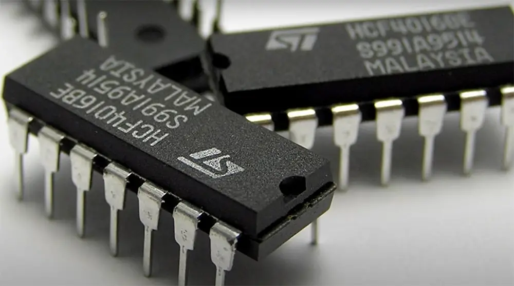
When you’re ready to move beyond simple projects and into something that interacts with the world around you, it’s time to start thinking about sensors! These days, there are sensors for just about everything: motion, light, temperature, pressure, sound…the list goes on and on. In this tutorial we’ll be using a flame sensor with Arduino. [1]
Arduino Interfacing and Its Purposes
Arduino interfacing is defined as the connectivity between two devices which are capable of exchanging data with each other. The idea behind Arduino interfacing is that it will allow you to connect two devices together so they can work in tandem. For example, you can utilize Arduino interfacing to connect a mouse and keyboard to a computer so that you can control the computer with them.
What Are Flame Sensors
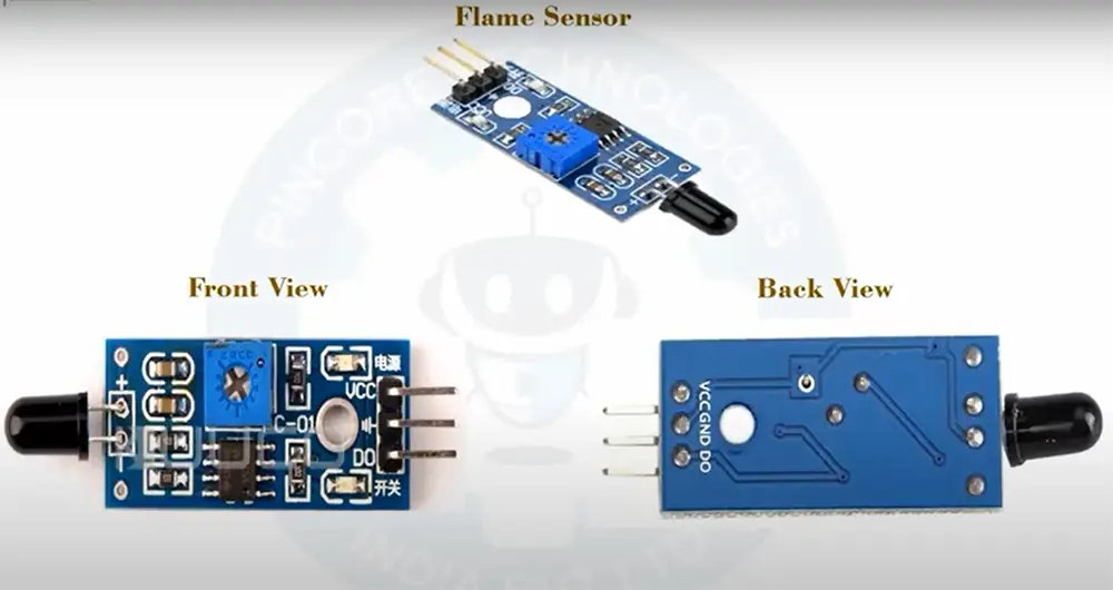
A flame sensor is a sensor that can detect the presence of a flame, or fire. The sensor is used in a variety of applications, including fire alarms and smoke detectors. There are various types of flame sensors: UV, IR, and visible light. The most common one however is infrared and this is the sensor we will be using for this task.
Flame sensors have a large variety of applications, some of which are listed below:
How Does a Flame Sensor Detect Flames?
An infrared flame sensor consists of an infrared receiver and an amplifier. The most important part of the sensor is the IR receiver, which is usually a small chip with three-four pins: ground (GND), power (VCC), and either digital output or both digital and analogue outputs.
Flame sensors are available in a variety of shapes and sizes, but they all work in essentially the same way. The receiver is used to detect the infrared radiation emitted by a flame, and the amplifier is used to amplify the signal from the receiver. The output of the amplifier is then sent to a microcontroller, such as an Arduino.
The sensor’s receiver is sensitive to a specific range of wavelengths of IR light, usually between 760 nm to 1100nm, which covers most of the infrared spectrum.
When the sensor detects a flame, it sends a signal to the microcontroller that can be used to trigger an event, such as turning on an LED or sounding an alarm.
When there is no flame present, the receiver does not detect any reflected light from the emitter. However, when a flame is present, the heat from the flame causes the emitter to emit more IR light than usual. This increased amount of IR light is detected by the receiver, and an output signal is generated.
The output signal from the receiver can be used to trigger a fire alarm, or turn on an LED, for example. In this tutorial, we’ll use the output signal to turn on an LED. So, let’s get started! [3], [4], [5], [6]
What Will You Need For This Project
First, we will need to gather all the necessary materials. For this project you will need:
An Arduino Uno
A breadboard
A breadboard is used to build temporary prototypes and experiments with circuits without having to solder them.
A buzzer
A buzzer is an electronic sound-making device. It can be used to create a variety of sounds, from a simple beep to a complex melody. Buzzers will let us know if the fire is close.
A flame sensor
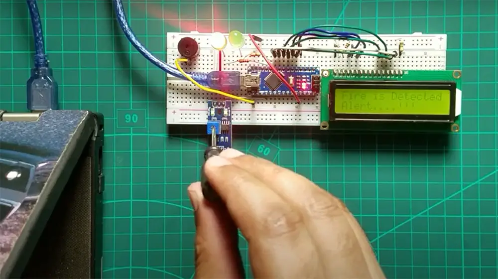
As mentioned above, a flame sensor is a sensor used to detect the presence of fire. It consists of an infrared receiver and an amplifier. In this case we will be using an infrared sensor.
Power supply
For this project we will need a power supply that can provide enough volts for your project to function. A USB power supply or a nine-volt battery will work fine.
A LED
While not mandatory for making the project work, we will also use an LED as a light-emitting diode to provide visual feedback. LEDs are used in a variety of applications, including indicator lights, flashlights, and traffic lights. For this project we will be using an LED to indicate when a flame is detected.
Jumper wires
Jumper wires are used to connect the components on the breadboard to each other. They come in various lengths and colors. It is recommended to use a few colors so you can keep track of which wire goes where.
A 1KΩ resistor (optional)
A resistor is used to limit the current flowing through the LED. If you do not have a resistor, you can use a piece of wire instead. Just make sure the wires are not touching each other.
So, let’s jump right into it! [3], [4], [5], [6]
Interfacing a Flame Sensor with Arduino
Build a circuit
Now that we have all the necessary materials, it’s time to start building our circuit! First, let’s connect the flame sensor to the Arduino.
Connecting the flame sensor to the Arduino is pretty simple. The flame sensor has three pins: GND, VCC, and Signal. Connect GND to ground on the Arduino, VCC to + five volts on the Arduino, and Digital Output pin to digital pin 11 on the Arduino.
Now, let’s connect the buzzer. The buzzer as well has two pins: positive and negative. Connect the positive lead to the 12 pin on your Arduino board and the negative lead to ground. [4], [5], [7]
Entering the code
Now that we have our circuit all set up, it’s time to write some code!
The first thing we need to do is connect your Arduino with your computer using a USB cable. Once the Arduino is connected, open up the Arduino IDE.
Even if you have never used the Arduino IDE or edited the code before, don’t worry! This code is very simple and easy to understand.
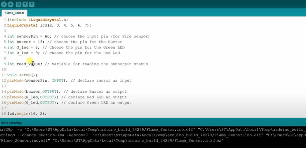
The first thing we need to do is include the library for the flame sensor. We do this by including the following line of code at the top of our sketch:
include “SoftwareSerial.h”
This line tells the Arduino IDE to include the software serial object library when compiling your code.
Next, copy the rest of the code as follows:
int sensorPin = A0;
int sensorValue = 0;
int buzzer = 12;
int LED = 9;
void setup() {
pinMode(led, OUTPUT);
pinMode(buzzer,OUTPUT);
Serial.begin(9600);
}
void loop()
{
flame_detected = digitalRead(flame_sensor);
if (flame_detected == 1)
{
Serial.println(“FIRE! FIRE! FIRE!”);
digitalWrite(buzzer, HIGH);
digitalWrite(LED, HIGH);
delay(200);
digitalWrite(LED, LOW);
delay(200);
}
else
{
Serial.println(“All is good!”);
digitalWrite(buzzer, LOW);
digitalWrite(LED, LOW);
}
delay(1000);
}
Explaining the code
Now that we have our code all set up, let’s go over it so we can understand what each line does.
The first two lines define the variables we will be using in our sketch. The sensorPin variable is used to store the analog pin number to which our flame sensor is connected. The LED variable stores the digital pin number of the LED and the buzzer variable stores the pin number of the buzzer.
Baud rate is the number of times per second that the data is sent. We set the baud rate to be high so that we can send a lot of data quickly.
Next, we have the setup function. This function is called only once when your Arduino board powers on or resets. We use this function to initialize any variables or settings that we need for our sketch.
In this case, we use it to set the digital pins for our LED and buzzer as output pins. We also use it to start the Serial communication so we can print messages to the Serial Monitor.
The loop function is where all the action happens! This function runs over and over again, in a loop, as long as your Arduino has power.
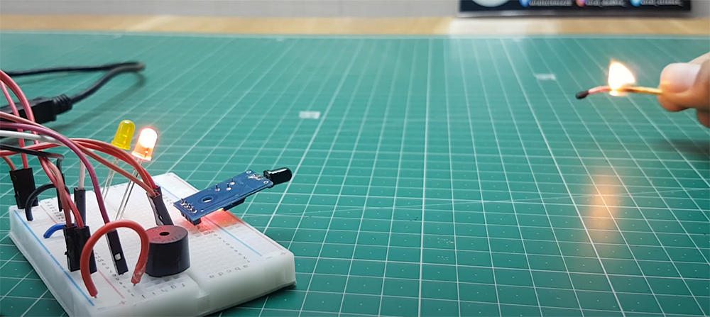
In this case, we use it to read the value of the flame sensor and store it in the sensorValue variable. Test it by bringing a flame close to the sensor. We then check if the value is above a certain threshold.
If it is, that means there is a fire and we print a message to the Serial Monitor saying “FIRE! FIRE! FIRE!”.
We also turn on the buzzer and LED for half a second before turning them off again. If there is no fire, we simply print “All is good!” to the Serial Monitor. You can edit both of these messages as you wish.
When the sensor is not exposed to a flame, the output (OUT) pin is LOW. When the sensor is exposed to a flame, the output (OUT) pin goes HIGH. The threshold at which the output changes from LOW to HIGH depends on the sensitivity of the sensor. Some sensors are more sensitive than others and will go HIGH at lower flames, while other sensors require a larger flame to produce a HIGH output.
At the end of our loop function, we add a delay of one second so our sketch doesn’t run too fast.
And that’s it! You should now have a working Arduino flame sensor circuit now! [3], [4], [5], [6], [7]
Where Can You Use the Arduino Flame Sensor?
Now that you know how to interface a flame sensor with Arduino, you might be wondering what sorts of projects or applications you can use it for.
One common use for the Arduino flame sensor is in security systems. You can use it to create an alarm that goes off when there is a fire.
Another use for the Arduino flame sensor is in making robots. You could use it to make a robot that avoids fire or one that follows a candle.
The possibilities are endless! So go out and experiment with your new found knowledge about interfacing a flame sensor with Arduino! [5], [6]
Interfacing a Flame Sensor with Arduino: A General Comparison
This table provides a general comparison of key aspects when interfacing a Flame Sensor with Arduino. Flame sensors are essential components in fire detection systems, and connecting them to an Arduino can enable effective fire monitoring. This table highlights common features such as operating voltage, output type, response time, LED indicator, built-in comparator, and adjustable sensitivity.
| Aspect | Description |
|---|---|
| Operating Voltage | Typically 5V, but some sensors may operate at different voltage levels. |
| Output Type | Flame sensors can provide analog, digital, or both types of outputs. |
| Response Time | The time taken by the sensor to respond to the presence of flames or fire sources. |
| LED Indicator | Indicates whether the flame sensor has a built-in LED to show the status of flame detection. |
| Built-in Comparator | Specifies whether the flame sensor has a built-in comparator to provide a digital output. |
| Adjustable Sensitivity | Indicates whether the sensitivity of the flame sensor can be adjusted as per requirements. |
Explanation:
- Operating Voltage: Flame sensors typically require a supply voltage of 5V, which is commonly available in Arduino boards. However, some flame sensor models may operate at different voltage levels, and it’s essential to ensure compatibility with the Arduino’s voltage.
- Output Type: Flame sensors can provide different types of outputs. Analog output provides a continuous range of values based on the detected flame intensity, while digital output typically gives a high or low signal based on whether a flame is detected or not. Some sensors may offer both analog and digital outputs.
- Response Time: The response time of a flame sensor refers to how quickly it detects the presence of a flame or fire source. A faster response time is generally preferable for real-time fire detection.
- LED Indicator: Many flame sensors come with a built-in LED that lights up when a flame is detected. This LED indicator can be helpful for visual feedback during testing and troubleshooting.
- Built-in Comparator: Some flame sensors have a built-in comparator circuit that converts analog output to a digital signal for easy interfacing with microcontrollers like Arduino.
- Adjustable Sensitivity: Some flame sensors allow users to adjust the sensitivity level. This feature is beneficial for fine-tuning the sensor’s response to match specific environmental conditions.
This general comparison table covers the essential aspects to consider when interfacing a flame sensor with Arduino. Depending on your project requirements, you can select a flame sensor that best suits your application based on these features.
Check more Arduino guides to improve your skills:
- How to Make an Arduino Ohm Meter?
- How to Use a Microphone with Arduino?
- How to Stop an Arduino Program?
FAQ
How does a flame sensor work?
A flame sensor is basically an IR sensor which is used to detect the intensity of fire. It has two main parts: an infrared (IR) receiver and a transistor. The transistor acts as a switch that turns on when it detects fire.
The working principle of a flame sensor is very simple. When there is no flame, the circuit is open and no current flows through the transistor. But when there is a flame, the heat from the flame causes the transistor to conduct current, which closes the circuit and allows current to flow. This change in resistance can be detected by Arduino using one of its digital input pins. By monitoring this pin, we can know whether there is a flame or not.
How do you build a fire detection system with an Arduino flame sensor?
Building a fire detection system with an Arduino flame sensor is actually pretty simple. All you need is the sensor, either LED, buzzer or both, some wire, and an Arduino board. After you build a circuit, program your sensor using Arduino IDE and test it out!
Are there practical applications for Arduino flame sensors?
Yes, there are many practical applications for Arduino flame sensors. For example, you can use it to create a fire alarm or to detect the presence of a flame in a room.
Another useful application is to use the sensor to control an LED. By connecting the sensor to an LED, you can create a light that turns on when there is a flame present and turns off when there is no flame present. This can be used as a visual indicator to help you stay safe when working with open flames.
Finally, you can also use the sensor to track the intensity of a flame over time. By monitoring the intensity of the flame, you can learn about how quickly a fire is growing and how dangerous it may be.
What components do I need to interface a flame sensor with Arduino?
To interface a flame sensor with Arduino, you’ll need the following components: a flame sensor module, an Arduino board (e.g., Arduino Uno or Arduino Nano), male-to-female jumper wires, and a breadboard (optional, but recommended for prototyping).
Which pins on the Arduino should I connect the flame sensor to?
Typically, you can connect the flame sensor’s digital output pin to any of the digital input pins on the Arduino. Make sure to check the sensor’s datasheet or documentation to determine its digital output pin, and then choose a suitable digital pin on the Arduino.
How do I wire the flame sensor to the Arduino?
Connect one end of the male-to-female jumper wire to the digital output pin of the flame sensor. Then, connect the other end of the jumper wire to the digital input pin on the Arduino that you selected for the sensor. Ensure proper connections, and you’re ready to proceed.
What is the process of programming the Arduino for flame sensor interfacing?
First, make sure you have the Arduino IDE installed on your computer. Then, open the IDE and create a new sketch. Define the digital pin to which you connected the flame sensor as an input pin using the pinMode() function. In the loop function, use digitalRead() to read the flame sensor’s output and take appropriate actions based on the detected flame, like activating an alarm or turning off a gas valve.
Can I adjust the sensitivity of the flame sensor?
Yes, many flame sensor modules come with a potentiometer that allows you to adjust the sensitivity. By rotating the potentiometer, you can control the threshold at which the sensor considers a flame to be detected. Experiment with the potentiometer to find the sensitivity that best suits your application.
Are there any safety precautions I should consider when working with a flame sensor?
Absolutely. When interfacing a flame sensor, especially if you are testing it with an actual flame, exercise caution. Work in a well-ventilated area and keep flammable materials away. Avoid direct contact with the flame sensor during testing to prevent burns. If you are using the sensor in a fire detection system, ensure you have proper safety measures and backup systems in place.
Can I use multiple flame sensors with a single Arduino board?
Yes, you can use multiple flame sensors with a single Arduino board. Each flame sensor should have its digital output pin connected to separate digital input pins on the Arduino. In the Arduino code, you can read the status of each sensor individually and implement corresponding actions based on their outputs.
Is it possible to combine a flame sensor with other sensors in a project?
Absolutely! Combining a flame sensor with other sensors can enhance the functionality and capabilities of your Arduino project. For example, you can integrate a flame sensor with gas sensors, temperature sensors, or humidity sensors to create a more comprehensive fire detection and prevention system.
Where can I find example codes and tutorials for interfacing a flame sensor with Arduino?
You can find example codes and tutorials for interfacing a flame sensor with Arduino on various online platforms. Websites like GitHub, Arduino Project Hub, and various electronics forums often have projects and code samples related to flame sensors. Additionally, you can search for specific tutorials on YouTube and other educational websites.
Useful Video: Flame Sensor for Arduino with code
Conclusion
Conclusion paragraph: In this project, we interfaced an IR flame sensor with Arduino to detect when a fire was present. By doing this, we were able to create a system that would sound an alarm and light up an LED when it detected fire. This is a simple project, but it can be adapted for many different applications. You can experiment all you like and improve this project however you see fit, there’s no bounds to human imagination. Remember to stay safe when working with fire and have fun!
References:
- https://www.arduino.cc/
- https://www.arduino.cc/en/reference/serial
- https://www.theengineeringprojects.com/2017/08/flame-sensor-arduino-interfacing.html
- https://www.theengineeringprojects.com/2020/12/interfacing-flame-sensor-with-arduino.html
- https://www.electronicshub.org/arduino-flame-sensor-interface/
- https://circuitdigest.com/microcontroller-projects/arduino-flame-sensor-interfacing
- https://www.instructables.com/Flame-detection-using-Arduino-and-flame-sensor/




Leave a Reply