
Building an Arduino ohm meter is a great way to learn about electronics, A/D conversion, and how to use the Arduino platform. It can also be a fun project for anyone who enjoys gardening or growing plants. In this article, we will answer some common questions about building an Arduino ohm meter. We will provide useful tips and advice on how to make your own Arduino ohm meter. Let’s get started!
What is an Arduino?
The Arduino is an open-source, easy to use electronics platform that has been around for years. It’s intended for anyone making interactive projects. What can you make with it? Well, anything really. It’s open-source and based on easy to use hardware/software so anyone – even kids! The environment is sensed by receiving inputs from different sensors which then lets us affect our surroundings through controlling lights motors.
The Arduino can be controlled with an IDE. The software provides you the ability to create, edit then upload code onto this device in order for it to do what we want. This is incredibly convenient and it makes fixing something that doesn’t work an easy job. Arduino uses a simplified version of C++, making it easier to learn than other programming languages.
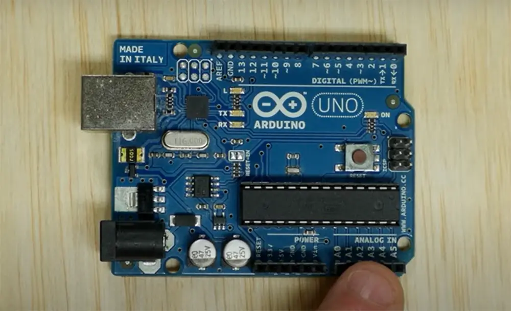
In this project, we will be using Arduino Uno. Arduino Uno board is perfect for beginners who want to start making their own electronics projects. It has 14 digital pins, six analog inputs, as well 16 MHz ceramic resonator, so it’s no secret as to why. For more convenience, it also comes with an ICSP header, reset button and USB connection for connecting it to PC or other devices.
Arduino board comes with pins that can be used to connect various external devices such as LEDs, motors and so much more. Each pin has a specific function written next to it that tells what type of connection you need without having to guess. This simplifies your job big time.
Analog pins are used to read sensors that give out analog voltage signals like temperature sensors, flex sensors, etc. These pins are marked with “A” in front of their number. For example, A0 is the first analog pin and A15 is the last one.
Arduino Uno can be powered by using the USB cable from your computer or by using an external power supply. If you want to use it, than the power supply needs to be connected to the Arduino board through the power jack. [1], [2], [3], [4], [5]
Uses of Arduino Ohm Meter
An Arduino ohm meter can be used in many different ways. You can use it to measure the resistance of your circuit, or you can use it to find out how much current is flowing through an object in a circuit. You can also use it to measure the voltage of a circuit.
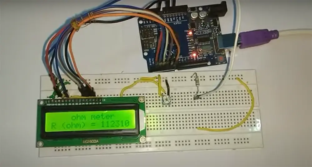
In this task, we will create a device that measures an unknown resistance and displays it on a screen. [2], [3], [4], [5], [6], [7]
What Will You Need for This Project
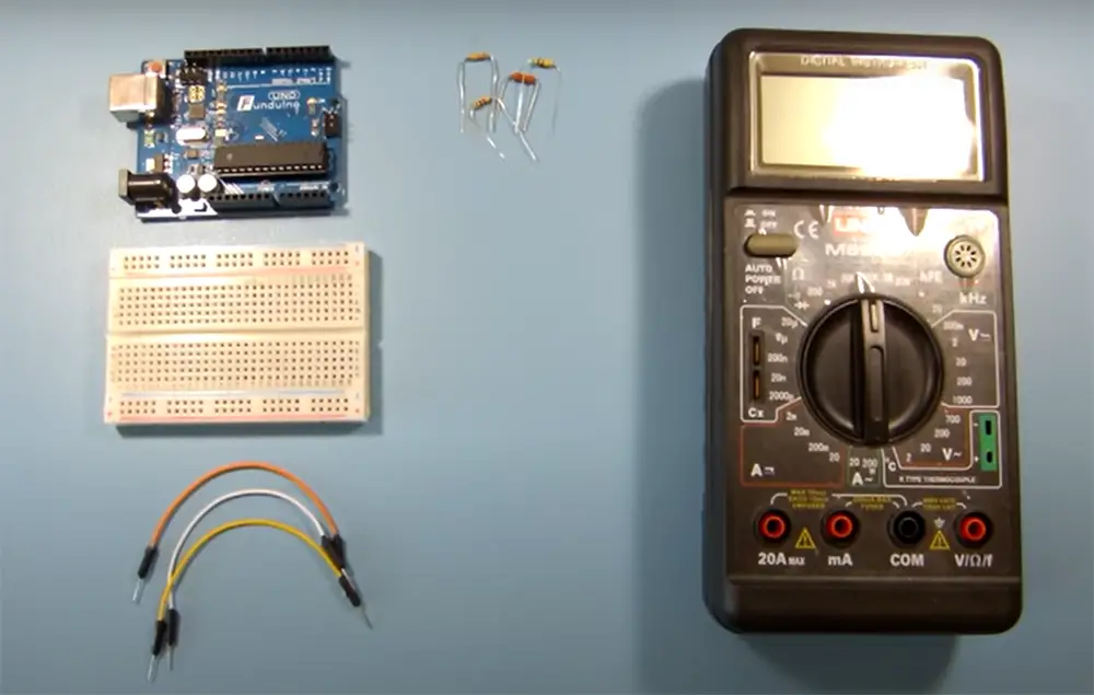
- Arduino Uno
- Breadboard
- Jumper wires
- Rotary potentiometer
- 16×2 LCD
- Resistor of at least 470 ohm
- Resistors (one with unknown value and one with a known value)
We will need an LCD for this project so that we can see the resistance value that we are measuring. Breadboard is used to make all the necessary connections. The potentiometer is used as a variable resistor. The known value resistor is used to create a voltage divider circuit with the unknown value resistor, which is then used to measure the resistance of the unknown resistor.
The main secret behind this project is a voltage divider network. A voltage divider network is created when two resistors are connected in series across a voltage source. The output voltage of the voltage divider network is equal to the input voltage multiplied by the ratio of the two resistors.
Now that you know what an Arduino ohm meter is and how it works, let’s get started with this project! [2], [3], [4], [5], [6], [7]
Making an Arduino Ohm Meter
First, you need to gather all of the materials listed above. Once you have all of the materials, you can begin building your circuit.
Next, you have to connect the Arduino to the breadboard. This is done by connecting the ground (GND) pin on the Arduino to one of the power rails on the breadboard with jumper wires. Then, connect the V5 pin to the other power rail on the breadboard. Finally, connect one of the digital pins on the Arduino (we used digital pin 13) to one of the rows on the breadboard.
It’s recommended that you use jumper wires of different colors to connect the different parts of the circuit. This will make it easier to keep track of which wires are connected to what. You may also use alligator pins to make them more stable.
Now that your Arduino is connected to the breadboard, it’s time to join the resistors. In this arrangement, we must establish a connection between the two resistors in series. The known resistor should be connected to ground and analog input pins, while the unknown resistor should be linked to the analogue input with one end, and to a positive voltage source with the other.
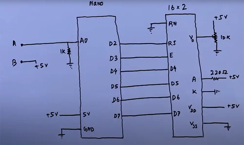
After that, we will need to set up our 16×02 LCD display. For that follow the pin description for LCD is as follows:
VSS: Ground
VDD: +VCC (Positive power supply)
VO: Regulates the contrast of the LCD display. This pin should be connected to a variable resistor (potentiometer or trimpot) so that we can change its value and, as a consequence, the contrast of our display. We connect it through a resistor to ground so that we can have more control over it.
RS: Data/command register select pin. It tells the LCD if the data being sent is text data or command data. When sending text data RS must be 1 (HIGH), when sending commands RS must be 0 (LOW).
RW: Read/write pin. It tells the LCD if we are writing data to it (making it display something) or reading data from it (for example, when using the LCD in conjunction with an Arduino). Since we only want to write to the LCD, this pin should always be 0 (LOW).
E: Enable pin. This is used to tell the LCD that we are sending it data. A HIGH pulse on this pin will enable the LCD and a LOW pulse will disable it.
D0-7: Data pins 0–7. These carry the actual text data that we want displayed on our screen.
A & K: Backlight anode and cathode pins respectively that power up the backlight LED. If we connect the anode to +VCC and the cathode to ground, the backlight will be on.
Now that you have all of your materials and know which pins go where, you can continue wiring your circuit.
Once the LCD is linked, you need to connect the potentiometer. The potentiometer should be connected from ground to power supply, and one of its middle pins should be connected to one of the rows on the breadboard.
It’s time to write some code! Now that you have your circuit all wired up, connect Arduino to your computer with a USB cable and upload the code below. Don’t forget to replace the values with the ones of your own. [2], [3], [4], [5], [6], [7]
Programming your Arduino
Once you have your development environment set up, connect your Arduino board to your computer using a USB cable. The first time you connect an Arduino board, you will need to install drivers for the board. After that, the IDE should automatically detect the board and you’re ready to upload code.
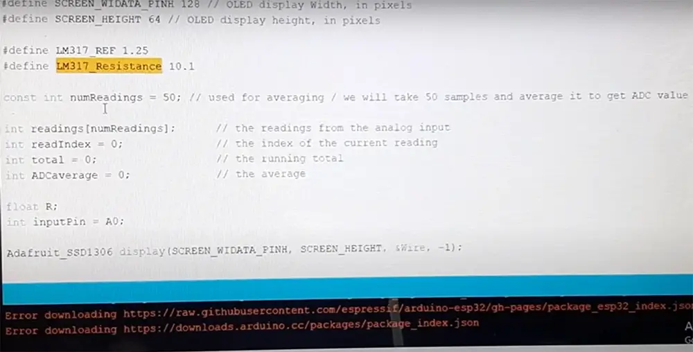
Copy the following code into an editor:
int analogPin = 0;
int raw = 0;
int Vin = 5;
float Vout = 0;
float R1 = 1000;
float R2 = 0;
float buffer = 0;
void setup(){
Serial.begin(9600);
}
void loop(){
raw = analogRead(analogPin);
if(raw){
buffer = raw * Vin;
Vout = (buffer)/1024.0;
buffer = (Vin/Vout) – 1;
R2= R1 * buffer;
Serial.print(“Vout: “);
Serial.println(Vout);
Serial.print(“R2: “);
Serial.println(R2);
delay(1000);
}
}
Explanation of the code
The first thing we do is declare some variables. analogPin is the pin that the voltage divider is connected to, raw is the read value from analogPin, Vin is the power supply voltage, Vout is the voltage drop of an unknown resistor, R1 is the known resistor, R2 is the unknown resistor, and buffer is an intermediary value used in the calculations. [2], [4], [8]
Getting the results to LCD
If you wish to get your results on LCD, it’s easy to do. You just have to use the code below.
#include <Wire.h>
#include <LiquidCrystal_I2C.h>
LiquidCrystal lcd(2,3,4,5,6,7); //rs,e,d4,d5,d6,d7
int analogPin = 0;
int raw = 0;
int Vin = 5;
float Vout = 0;
float R1 = 1000;
float R2 = 0;
float buffer = 0;
void setup(){
lcd.begin(16, 2);
}
void loop(){
raw = analogRead(analogPin);
if(raw){
buffer = raw * Vin;
Vout = (buffer)/1024.0;
buffer = (Vin/Vout) – 1;
R2 = R1 * buffer;
lcd.setCursor(0, 0);
lcd.print(“Vout: “);
lcd.print(Vout);
lcd.setCursor(0, 1);
lcd.print(“R2: “);
lcd.print(R2);
delay(1000);
}
}
How this code works
This is a very simple code that just uses the built in functions of Arduino IDE. We have used the LiquidCrystal library to communicate with an LCD display. The library already has a lot of predefined commands like lcd.begin(), lcd.setCursor(), and lcd.print().
delay(1000) just tells the Arduino to wait for one second before repeating the loop.
In the void setup() we have only used lcd.begin(16,02) which means that our LCD display is 16 columns wide and has 02 rows. If you have a different kind of LCD display, then change these parameters accordingly. [2], [4], [8]
Calculating Resistance using Arduino Ohm Meter
To understand how this is actually going to work, we should explain more about Ohm’s Law.
Ohm’s Law is one of the most important laws in physics and it is also very useful to us electrical engineers.
It states that:
“The current through a conductor between two points is directly proportional to the potential difference across those two points.”
In simple words, this law tells us that there is a linear relationship between voltage and current in a circuit.
We can use this information to measure the resistance of different materials after creating a very simple circuit with an Arduino.
And with the help of Ohm’s Law, we can create the voltage divider equation which is going to be very useful for us.
The equation is as follows:
Vout=R1/(R1+R2)*Vin
Where:
Vout = Voltage measured at the current junction
R1 = unknown resistor
R2 = Resistance of the known resistor
Vin =Supply voltage (in our case it will be the voltage from the 5V pin of Arduino)
Arduino can measure voltage using one of its analog input pins. This is because the Arduino has an inbuilt Analog-to-Digital Converter (ADC). The ADC converts an analog signal, such as voltage, into a digital number that can be read by the Arduino. This digital number is then used to calculate the resistance. This is how we can find the voltage of Vx.
Now let’s see how this works in practice. We used a simple circuit with a known resistor and an unknown resistor connected in series. The known resistor will act as a reference point for our measurement and so we should follow the next equation.
R2 = Vout * R1 / (Vin – Vout)
Remember, when doing your own calculations, replace the values with the ones you use in your circuit. This will give you a correct result for your own project. [2], [3], [5], [6], [7]
Read more guides to improve your Arduino skills:
- Interfacing a Flame Sensor with Arduino Guide
- How to Use a Microphone with Arduino?
- How to Stop an Arduino Program?
FAQ
Is Arduino Uno better than other Arduino boards?
The Arduino Uno is a great board for beginners, but there are many other Arduino boards that offer different capabilities. If you’re looking for more power, the Arduino Mega might be a better option. If you need something smaller, the Arduino Nano might be a better option.
Can an Arduino measure resistance?
Yes, an Arduino can measure resistance by using one of its analog input pins. To do this, you’ll need to create a voltage divider circuit with a known resistor value, and then measure the voltage across the resistor with the Arduino. The voltage divided by the resistor value will give you the resistance in ohms. You can also use an external multimeter to measure resistance, and then use the Arduino to read the multimeter’s display.
Can Arduino measure voltage?
Arduino can measure voltage using the analog input pins. The Arduino has an analog to digital converter (ADC) that measures the voltage between 0 and the reference voltage (Vref) on the AREF pin. The reference voltage is usually set to five volts. So, if you’re using a five volt power supply, your maximum voltage would be four volts.
To measure voltage with an Arduino, you need to use an external power source that is higher than the Arduino’s operating voltage. You also need a resistor divider circuit to divide down the external voltage so that it is within the range of voltages that the ADC can measure.
What are the benefits of using an Arduino ohm meter?
An Arduino ohm meter can be used to measure the resistance of any conductor, whether it’s a resistor or a wire! By measuring the resistance, you can calculate the amount of current that will flow through the conductor.
Arduino ohm meters are especially useful for testing circuits and components before soldering them into place. This way, you can make sure everything is working correctly before making a permanent connection.
Ohm meters can also be used to troubleshoot problems in existing circuits. By measuring the resistance of different parts of the circuit, you can narrow down where the problem is located and make repairs accordingly.
What are some of the challenges that you faced when making your Arduino ohm meter?
One of the challenges I faced when making my Arduino ohm meter was sourcing all of the necessary components. In addition, putting all of the components together and getting them to work correctly took some time and effort. However, the end result was worth it!
Another challenge I faced was making sure that the Arduino ohm meter was accurate. To do this, I tested it against a known good reference meter. After a few adjustments, I was able to get it to be within +/- 0.02% accuracy, which is pretty good.
How accurate is the Arduino ohm meter?
We all know how important accuracy is when dealing with electronics. The last thing you want is a component to fail because your readings were off. So, how accurate is the Arduino ohm meter?
In general, the Arduino Ohm Meter is quite accurate. Most of the time, you should expect it to be within 2 units of accuracy. However, there are a few factors that can affect its accuracy, such as the voltage used and the resistance of the load.
Can you measure resistance with an Arduino?
To measure resistance with an Arduino, you’ll first need to create a voltage divider circuit. This will step down the voltage from your power source so that it’s within the range that your Arduino can handle. Then, you can use one of the Arduino’s analog input pins to measure the voltage across the resistor. Finally, you can use Ohm’s law to calculate the resistance from the measured voltage and known values for the other components in your circuit.
Can an Arduino be used as a multimeter?
An Arduino can be used as a multimeter if you build it correctly. Arduino can be set-up to measure Voltage, Current, and Resistance.
Thanks to the fact that Arduino has several input pins, we can easily build a multimeter using an Arduino. We will need to use some extra components, but it’s not difficult to find these parts or to solder them onto the Arduino board. You will need to find resistors, current detector, LCD display and an Arduino Uno board among some other things.
Once assembled, you can easily turn your Arduino into a multimeter. You can use it to measure voltage, current, and resistance.
Can an Arduino read current?
Yes, an Arduino can read current. Arduino has an input called an analog input pin. This allows the Arduino to read a voltage between 0 and the reference voltage (usually around five volts). The Arduino can then use this information to calculate the current.
However keep in mind that the Arduino isn’t as reliable as a commercial multimeter when it comes to reading current.
Can Arduino measure voltage?
Arduino can measure voltage using the built in ADC. The Arduino has a reference voltage of five volts. This means that the maximum voltage that can be read by the Arduino is five volts. Anything higher than five volts will damage the Arduino.
Boards like Arduino Uno will have a higher voltage tolerance while other boards may not. You can check the voltage tolerance of your Arduino by checking the datasheet.
How do you calibrate your Arduino ohm meter?
Calibrating your Arduino sensors is a process of matching the readings of your sensor to known values. To calibrate your Arduino ohm meter, you will need to upload a relevant sketch to your Arduino, and then use your Arduino Ohm meter to take readings of various resistances, usually it’s two extremes. Once you have your sensor readings, you can adjust the values in your sketch until they match the readings from your multimeter.
Keep in mind, you always need to wait for the sketch to finish uploading before proceeding with the calibration! This is usually easy to identify. Simply take a look at pin 13 on your Arduino. If it’s lit up orange, the sketch is still uploaded. When it turns blue, the sketch has finished uploading and you can continue.
How accurately can Arduino measure voltage?
Arduino can measure voltage with an external ADC (Analog to Digital Converter) with an accuracy of around +/- 2*LSB.
How do you read this? This means that Arduino will be at least 9.8mV off with its measurements. However keep in mind that accuracy is affected by many other factors such as the voltage reference used, wiring, and noise.
Useful Video: How to Make an Arduino Ohm Meter
Conclusions
Arduino is a great tool for creating interactive electronics projects. Not only is it fun to play around with, but you can also use it to make some pretty cool things too. One of those things is an Arduino ohm meter.
In this article, we showed you how to make your own Arduino ohm meter using a few simple components and code it in a way for it to measure an unknown resistance and then display the value on a LED screen. Now it’s time for you to get creative and make something amazing!
References:
- https://www.arduino.cc/en/Guide/Introduction/
- https://circuitdigest.com/microcontroller-projects/arduino-ohm-meter
- https://www.programmingelectronics.com/ohmmeter/
- https://www.circuitbasics.com/arduino-ohm-meter/
- https://www.instructables.com/How-to-Make-an-Arduino-Ohm-Meter/
- https://www.engineersgarage.com/diy-arduino-based-ohmmeter/
- https://simple-circuit.com/arduino-auto-ranging-ohmmeter-lcd/
- https://www.hackster.io/meworkstelugu/making-ohm-meter-using-arduino-and-16-2-lcd-ca94bd