
Do you want to know how to build a prototype electronic circuit? It can be a daunting task, but with the right information and tools, you can do it! In this article, we will provide a comprehensive guide on how to create a prototype for your next electronics project. We’ll answer some common questions, give helpful tips, and provide resources that will make the process easier for you. So whether you’re just starting out or you’re looking for ways to improve your current process, read on for everything you need to know about how to build a prototype electronic circuit!
The Definition of the Prototyping Process
In general, prototyping is the process of creating a model of something before creating the real thing. When you prototype a circuit, you’re creating a temporary version of the circuit that you can use to test out your ideas or troubleshoot problems.
Creating a prototype circuit is usually quicker and cheaper than building a permanent one because you don’t need to worry about making it look nice or using all the right materials. You can also experiment with different designs more easily when you’re prototyping because it’s easy to make changes to a prototype than it is to a finished product.

Many DIYers build their circuits with the help of perfboards, stripboards and breadboards. These are all types of prototype boards that make it easy to build a circuit without having to solder everything together.
Assuming you have all of the necessary materials, building a prototype circuit is actually not that difficult. But let’s take a look at the prototype board options in detail. [1], [2], [3]
Different Prototyping Boards
All three boards are made of plastic and have metal tracks running through them. The main difference between perfboards, stripboards and breadboards is how easy they are to use. Perfboard is the most difficult to use because you have to carefully plan out your circuit before you start soldering components to the board. Stripboard is slightly easier to use because you can cut the tracks on the board to re-route your circuit if necessary and breadboard is the simplest one to use, because it doesn’t require you to solder anything, hence it is ideal for beginners and pros alike.
Perfboards
Perfboard is a thin, rigid sheet of fiberglass or paper that has a grid of small holes drilled into it. These holes have tiny spaces of 0.1 inches between them and are connected by metal traces on the back of the board.
Here’s a quick overview of how to use perfboard to build a circuit:
- Cut the perfboard to size using a sharp knife or wire cutters.
- Create a schematic of your circuit or find one online.
- Place and solder the components and wires into place according to your scheme. Make sure all of the connections are secure and there are no shorts between adjacent traces.
- Test your circuit to make sure it works as expected. [2]
Stripboards
Stripboard is a type of perfboard with parallel strips of copper running down the middle. It’s also called a veroboard or a copperclad board. To use a stripboard, you may need to cut the strips of copper that connect the holes you want to use. Components are placed on the side opposite to the copper tracks, and are soldered to them only later.
You can use a hobby knife or a pair of wire cutters to do this. Just be careful not to damage the surrounding copper or the plastic board. Once you’ve cut the strips, you can solder your components into place and connect them with jumper wires.
Stripboards are great for simple circuits but they can be tricky to use for more complex designs because it’s easy to accidentally short circuit something when you’re cutting the copper strips. [4], [5]
Breadboards
A breadboard is a rectangular plastic board with rows of metal contacts called “terminals” that are used to connect electronic components.
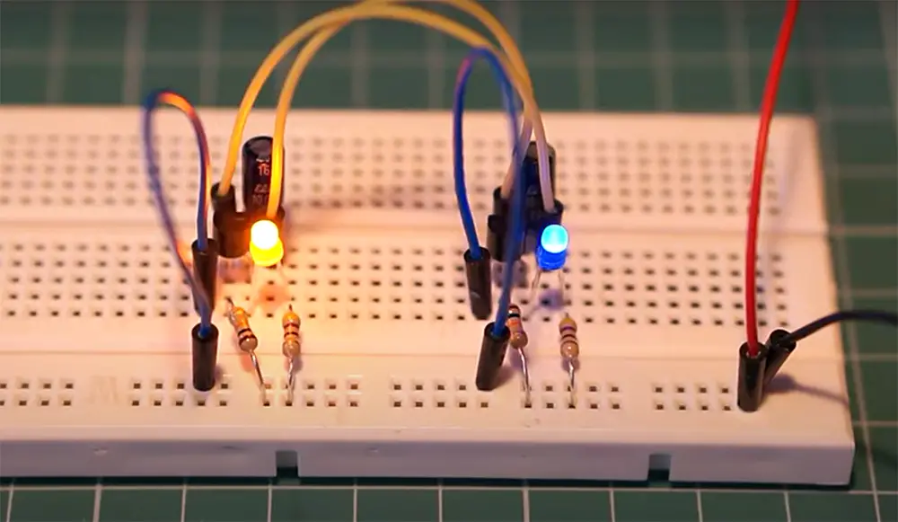
Breadboards are one of the most common ways to prototype a circuit because they’re easy to use and you don’t have to solder anything. Breadboards have a bunch of tiny metal clips that connect the holes in the board.
You can then use jumper wires to connect the different parts of your circuit. The great thing about breadboards is that they’re reusable so you can experiment with different designs without having to start from scratch each time.
How to Use a Breadboard?
Breadboards are one of the most common tools for prototyping and experimenting with electronics. But you still need to build a schematic plan for your future creation.
To use a breadboard, you just need to insert your components into the right holes. The holes are connected by metal clips, so the components will be securely held in place.
Board has vertical strips called power rails that are used to provide power to your circuit. The red and black power rails are connected to the positive and negative terminals of your power supply. You can use these power rails to distribute power to all the components in your circuit. You can use jumper wires to connect the power rail to the correct power pin on your breadboard.
Jumper wires come in different lengths, so you can choose the right one for your needs. You can also get jumper wires with different connector types at each end. The most common type is the male-to-male jumper wire, which has a Male header (or pin) on each end.
Breadboarding is a great way to build temporary circuits for experimentation or troubleshooting because it’s quick and easy to set up and take apart. Plus, you don’t have to solder anything, so it’s perfect for prototyping. [1], [2], [3]
Prototyping Tips
Practice is important
Once you have a good understanding of the basics, you can start to build more complex circuits. You can also use other prototyping techniques such as stripboards and perfboards.
Use jumper colors of different colors
When you are working with a breadboard, it is helpful to use different colors for the jumper wires. This will help you to keep track of which wires are connected to which components. It’s also a good idea to label the jumper wires so that you know what they are connecting. So when you come back to your project at a later stage you won’t have to guess what each wire is for.
For example, if you were connecting an LED to a power supply, you might use a red jumper wire for the positive connection and a black jumper wire for the negative connection.
Use aligator clips
Alligator clips are a great way to connect electronic components together without having to solder them. This is particularly useful when you are prototyping a circuit as you can easily change the connections if you need to. Alligator clips come in different sizes and colors, so you can choose the ones that suit your needs.
Plan ahead
When working on a project, it’s always a good idea to have a plan. This will help you to stay organized and focus on the task at hand. It’s also a good idea to take photos of your work as you go so that you can refer back to them later. [6], [7], [8]
Comparison of Indicators for Building a Prototype Electronic Circuit
Building a prototype electronic circuit is a crucial step in the development of electronic products. This process involves several indicators that affect the quality and effectiveness of the prototype. In this table, we compare various indicators for building a prototype electronic circuit.
| Indicator | Definition | Importance | Tools | Cost |
|---|---|---|---|---|
| Board Type | The type of board used for the prototype, such as breadboard, perfboard, or PCB. | High | Breadboard, perfboard, PCB design software | Varies based on board type and size |
| Components | The electronic parts used for the prototype, such as resistors, capacitors, and microcontrollers. | High | Component distributor, soldering iron, multimeter | Varies based on component type and quantity |
| Soldering Technique | The method used to connect the components to the board, such as through-hole or surface mount soldering. | Medium | Soldering iron, solder, flux | Varies based on technique and equipment |
| Testing | The process of verifying the functionality of the prototype through testing and debugging. | High | Oscilloscope, logic analyzer, power supply | Varies based on testing equipment and complexity |
| Documentation | The recording of the prototype’s design, parts, and testing procedures. | Low | Text editor, drawing software | Minimal cost |
The table compares five indicators for building a prototype electronic circuit: Board Type, Components, Soldering Technique, Testing, and Documentation. Each indicator is defined and assigned an importance level, ranging from low to high. The tools required for each indicator are also listed, along with a cost estimate. This table can help electronic product developers make informed decisions about the indicators to prioritize in building a prototype electronic circuit.
Read more guides to upgrade your knowledge in electronics:
- How is a Microprocessor Different from an Integrated Circuit?
- What is Star Delta Starter Circuit?
- How to Solder Wires to Connectors?
FAQ
Why are breadboards good for prototyping?
Breadboards are excellent for prototyping because they provide a very reliable and consistent way to build circuits.
Another advantage of breadboards is that they’re easy to use. You don’t need any special tools or knowledge to use one, and they can be set up relatively quickly. This makes them ideal for experimenting with different circuit designs.
Finally, breadboards are reusable. So if you make a mistake or want to change something about your circuit, you can simply remove the components from the breadboard and start again. This makes them much more versatile than other types of prototype boards.
What is used to build the prototype of the electric circuit?
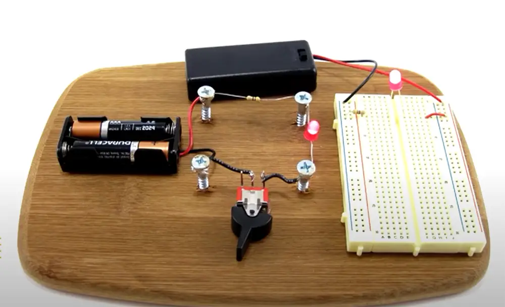
The first thing you need is a breadboard. You will also need some jumper wires – these are used to connect the different components on the breadboard together. Finally, you will need a power source – this can be a battery or a power supply connected to the mains.
Once you have gathered all of your materials, you can start building your prototype electric circuit. The first step is to identify where each component will go on the breadboard. Once you have done this, you can start connecting them together using the jumper wires. It is important to make sure that each connection is secure before moving on to the next one.
What are some of the most important things to keep in mind when building a prototype circuit?
Since a prototype is meant to be a working model of your product, it’s important to make sure that the circuit you build is as close to the final design as possible. This means paying attention to things like power requirements, component placement, and signal integrity. Always make sure your power source is appropriate for your project. If you’re using batteries, make sure they’re fresh and have the correct voltage.
It’s also important to keep in mind that a prototype is not necessarily meant to be perfect. In fact, it’s often helpful to purposely introduce errors into your prototype so that you can catch them early on. This way you can fix them before they become a problem in the final design.
Keep your circuit simple. The more complex your circuit is, the more likely it is to malfunction.
Lastly, you need to pay attention to detail. This means making sure all your connections are secure and that there are no loose wires. Even a small mistake can cause your entire circuit to fail.
What software do you use to design circuits?
There are a few different software programs that you can use to design circuits. The two most popular ones are Eagle and KiCad.
Eagle is a very user-friendly program that is great for beginners. It has a large online community where you can find support and resources. KiCad is also a great program with a lot of features, but it can be more challenging to learn.
If you want to try out both programs, there are many online tutorials that can help you get started. Once you have designed your circuit, you will need to export it as an image file so that you can print it out or view it on your computer screen.
What are the best tips for designing circuits?
If you’re new to circuit design, the best tips are to start simple and use online resources. For example, the website CircuitLab has a great online simulator that can help you test your designs before you build them.
Once you have a basic understanding of how circuits work, you can start experimenting with more complex designs. If you get stuck, there are plenty of online forums and chat groups where experienced engineers can help you troubleshoot your designs.
With a little practice, you’ll be designing complex circuits like a pro in no time!
How do you know if your circuit is working properly?
The best way to test a prototype circuit is to check the power module with a multimeter. If the readings are within the normal range, then the circuit is functioning correctly. If not, there may be a problem with the breadboard or soldering.
Another way to test a circuit is to use an oscilloscope. This will show you if there are any problems with the waveforms in your circuit.
It is also important to check for shorts between tracks on your PCB. A short can cause your circuit to malfunction and may even damage your components.
Are there any common mistakes people make when prototyping circuits?
One common mistake people make is not breadboarding their circuits before soldering. This can lead to errors in the circuit that are difficult to troubleshoot. Another mistake is using the wrong components for the job. Make sure to check the datasheets for the components you’re using to ensure they’ll work in your circuit. Finally, be careful of static electricity when working with sensitive electronics components.
Another common mistake is not double-checking their work for errors before powering on the circuit. This can cause damage to components or even start a fire if there are shorts in the circuit. Always use a multimeter to check for continuity and correct voltages before connecting power to your circuit.
Which is the easiest and fastest mode of prototyping a circuit?
There is no one definitive answer to this question as it depends on various factors such as the complexity of the circuit, whether you have all the necessary components on hand, and your own level of expertise. However, some methods are generally faster and easier than others. For example, building a prototype on a breadboard is often quicker than etching and soldering a PCB. Similarly, using pre-made modules or breakout boards can save time compared to wiring everything from scratch.
If you’re just starting out, it’s probably best to keep things simple and try out different prototyping methods until you find one that works well for you. With experience, you’ll develop a feel for which method is most appropriate in any given situation.
Why is circuit prototyping important?
Circuit prototyping is important for a number of reasons. First, it allows you to test your circuit design before committing to a final design. This can save you time and money in the long run, as you can make sure that your circuit works before moving on to the next step.
Second, circuit prototyping can help you troubleshoot your circuit. If something isn’t working right, you can quickly identify the problem and fix it. This can again save you time and money in the long run, as you won’t have to waste time or money on a faulty design.
Finally, circuit prototyping can simply be fun! It’s a great way to learn about electronics and get creative with your designs. You can experiment as much as you want, and there’s no right or wrong way to do it.
Which electronic components are used in most electrical appliances?
The electronic components used in most electrical appliances are capacitors, resistors, diodes, and transistors. Capacitors store energy in an electric field and release it when the current is interrupted. Resistors restrict the flow of current in a circuit. Diodes allow current to flow in one direction only. Transistors control the voltage and current in a circuit.
What happens if a circuit is not grounded?
If a circuit is not properly grounded, it can cause all sorts of problems. The most common problem is that the circuit will not work properly. Additionally, if there is a lot of electrical noise in the environment, it can cause the circuit to malfunction.
Another problem that can occur is that the circuit may overheat and catch fire. This is especially true if the power supply is not properly regulated. Improperly grounded circuits can also cause interference with other electronic devices nearby. It is therefore very important to make sure that your circuit is properly grounded!
Useful Video: #122: Electronic Circuit Construction Techniques: review of some prototype circuit building methods
Conclusion
That’s it! You now know the basics of how to use various prototype boards to build your own prototype circuits! As we figured out, it is best to start with a breadboard because of its simplicity. A stripboard and perfboard can also be used, but they will require more effort from your side. No matter what you choose, make sure to use jumper wires of different colors to avoid the mess of connections. If you are having trouble making everything work, don’t worry, practice makes perfect!
References:
- https://www.freecodecamp.org/news/whats-the-best-way-to-prototype-circuits/
- https://www.circuitbasics.com/how-to-use-prototyping-boards/
- https://medium.com/supplyframe-hardware/words-of-wisdom-prototyping-your-electronic-circuit-7e9b1253d8b1
- https://www.sciencedirect.com/topics/engineering/stripboard
- https://electronicsclub.info/stripboard.htm
- https://www.circuitcrush.com/7-tips-prototyping-circuit-design/
- https://www.analog.com/en/analog-dialogue/studentzone/studentzone-november-2016.html
- https://www.epanorama.net/blog/2020/05/15/electronics-circuits-prototyping/