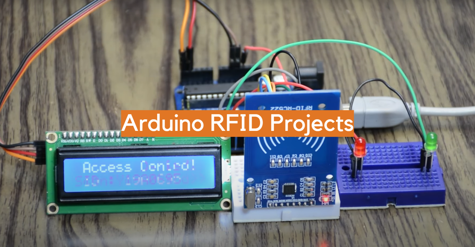
Arduino RFID Projects are becoming more popular with each passing day. This is because of the incredible possibilities that they offer. With an Arduino and some RFID tags and readers, you can do just about anything! In this article, we will answer some common questions about Arduino RFID projects. We will also provide some tips to help you get started on your own projects. Are you ready to learn more? Let’s get started!
Arduino in General
The Arduino platform consists of two main components: the microcontroller board (MCB) and the integrated development environment (IDE). The MCB contains a set of digital signal processing (DSP) chips, which allow it to interact with sensors and other devices. The IDE provides an easy-to-use interface for writing code that can be uploaded to the MCB.
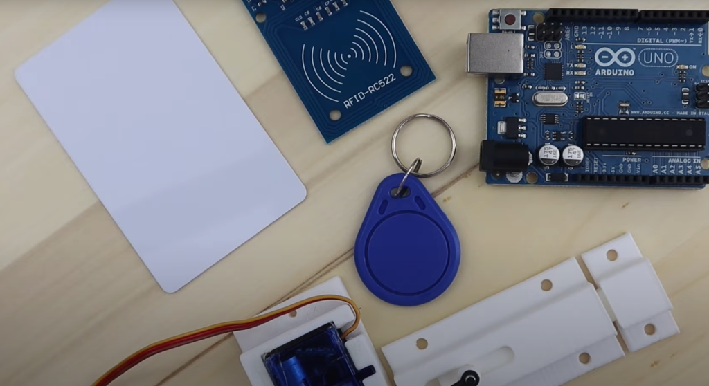
Using the tools provided by Arduino, users are able to develop custom electronics projects from the ground up. This can involve anything from building a simple LED blinker to creating complex home automation systems. With Arduino, it’s easy to integrate modern technologies like RFID and internet-of-things (IoT) devices into your projects.
Arduino is an incredibly versatile platform that allows users to create innovative projects quickly, easily, and cost-effectively. It’s also highly accessible thanks to its user-friendly interface and comprehensive online resources.
RFID stands for Radio Frequency Identification and is a technology used to identify objects or people. RFID uses radio waves to transmit data from a tag, reader, or both to an electronic device. It is similar to barcode technology but can store more information than barcodes.
RFID projects are projects involving the use of RFID technology. Arduino is an ideal platform to build RFID projects, as Arduino boards are both powerful and cost-effective. With a few simple components and some programming, you can create all kinds of RFID projects with Arduino. [1]
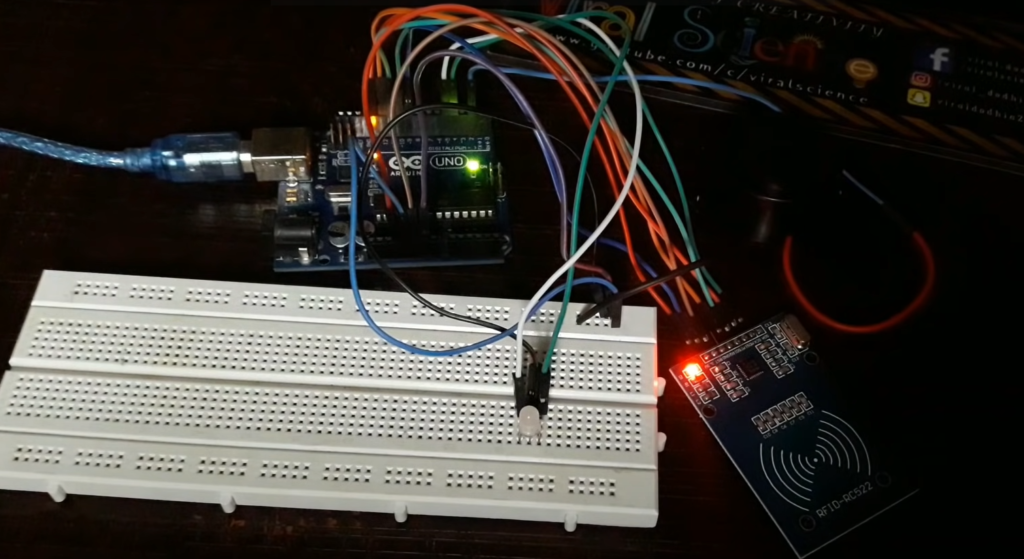
Best Arduino RFID Projects
Now that you have a better understanding of Arduino and RFID, we will cover some of the most popular Arduino RFID projects that you can make.
Windows PC RFID Lock
The first thing you’ll need to do when building an Arduino RFID lock with Windows PC support is getting all the components. Here’s a list of essential items:
- Arduino Pro Micro/Arduino Leonardo.
- MFRC-522 RFID module with RFID card.
- Male and female headers.
- Prototype PCB board.
- Wires.
- 10k ohm resistors – 3
Once you have the hardware ready, the next step would be building a prototype on the breadboard. To do this, you’ll need to connect the male and female headers to each of the components. This is important as it will ensure that all the components are securely connected.
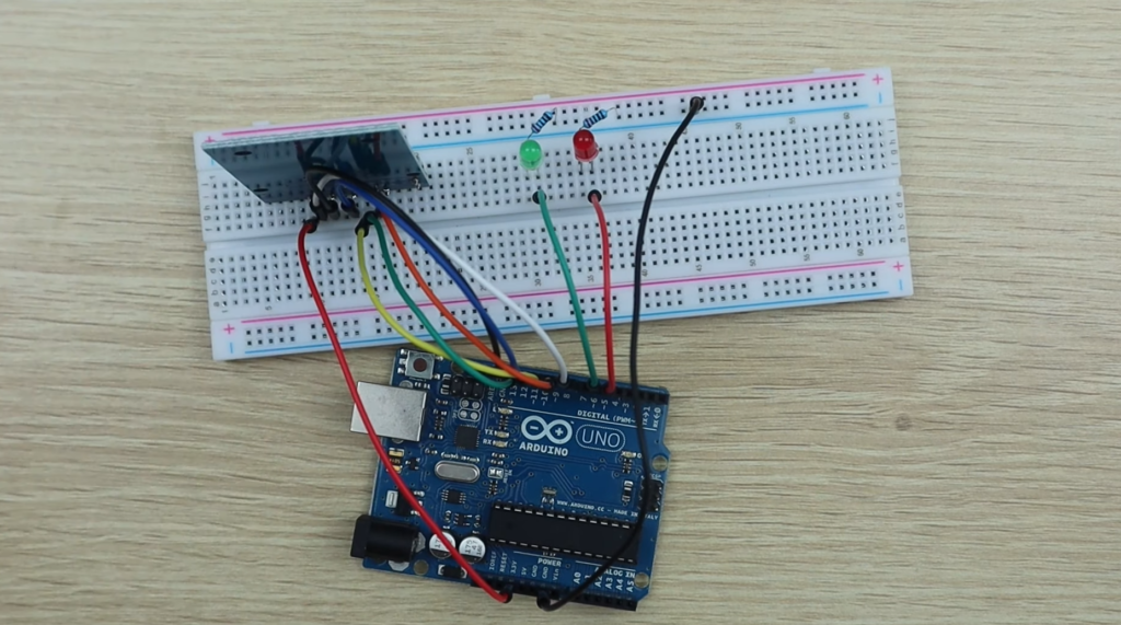
Once you make sure how everything is connected, it’s time to actually attach everything to the Arduino. Attach The RC-522 RFID VCC pin to the 3.3V of Arduino. Then, link the RST to pin 5 of Arduino and Ground to Ground.
MISO pin goes to pin 14 of Arduino, while MOSI connects to the 16th pin. SCK goes to pin 15. Lastly, SDA needs to be connected to pin 10 of Arduino.
Now you have everything connected and ready to go, it’s time to start writing code in the Arduino IDE. First, you’ll need to include necessary libraries for RFID module by using the following lines:
#include
#include
#include
#define SS_PIN 10
#define RST_PIN 5
#define KEY_RETURN 0xB0 //The hex value for the return key is 0xB0.
MFRC522 mfrc522 ( SS_PIN, RST_PIN ) ;
char Enter = KEY_RETURN; //Return key is declared as Enter.
String readid;
String card1=”48b45a10″; //Change this value to the UID of your card.
void setup( )
{
Serial.begin(9600);
Keyboard.begin();
SPI.begin();
mfrc522.PCD_Init();
}
void temp(byte *buffer, byte bufferSize)//function to store card uid as a string datatype.
{
readid=””;
for(byte i = 0;i<bufferSize; i++)
{
readid=readid+String(buffer[i], HEX);
}
}
void loop( )
{
if(!mfrc522.PICC_IsNewCardPresent())
{
return;
}
if(!mfrc522.PICC_ReadCardSerial())
{
return;
}
mfrc522.PICC_DumpToSerial(&(mfrc522.uid)); // Display card details in serial Monitor.
temp(mfrc522.uid.uidByte, mfrc522.uid.size);
if(readid==card1)
{
Keyboard.press(KEY_LEFT_GUI); //Press the left windows key.
Keyboard.press(‘l’); //Press the “l” key.
Keyboard.releaseAll(); //Release all keys.
delay (100);
Keyboard.press(Enter); //Press the Enter key.
Keyboard.release(Enter); //Release the Enter key.
delay(100);
Keyboard.print(“PASSWORD”); // Change this value to your Windows PIN/Password.
Keyboard.releaseAll();
delay(100);
Keyboard.press(Enter);
Keyboard.releaseAll();
}
else
{
return;
}
}
RFID and Bluetooth Door Lock
The next Arduino RFID project we’re going to tackle is a Bluetooth door lock. This is one of the most interesting Arduino RFID projects. It involves using an RFID reader to control a door lock with Bluetooth as a communication protocol. To complete this project, you’ll need:
- Arduino Uno
- 360 degree Servo
- HC-06 Bluetooth Module
- RC522 RFID Reader (Possibly Sintron, can not remember)
- 16 x 2 – 4 wire LCD screen
- RGB LED
- Two 220Ω Resistors
- Momentary Push Switch (to operate from the inside to lock/unlock the door)
- 10kΩ Resistor
- Two Double Back Boxes (1 approx 45mm depth and the other approx 33mm depth)
- Jumper Wires
- Power Supply
- Screws or strong double sided tape
- Servo Holder (I designed and printed my own)
- Two Double Blanking Plates
- Length of 12 core alarm cable (length dependant on placement)
- Two 5 amp Block Connectors (12 wires each)
Once you have all the required components, you can now begin to assemble the Arduino RFID project. Start by connecting the RFID Reader with the Arduino Uno. The VCC should be connected to Arduino’s 3.3V, the GND should be connected to Arduino’s GND, the RST (reset) should be connected to digital pin 9, and the SDA (data) should be connected to digital pin 10. MOSI, MISO, and SCK should all be connected to their respective pins (11, 12, 13).
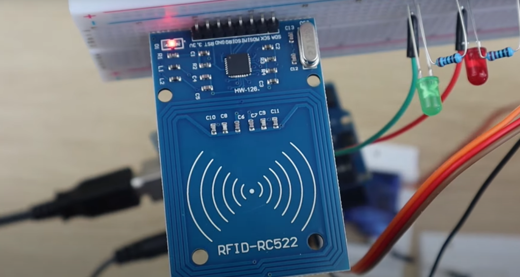
Next, connect the servo motor to the Arduino Uno. The VVC should be connected to 5V, the GND wire should be connected to GND, and the signal wire should be connected to digital pin 5.
Now it’s time to connect the LCD display. The VCC should be connected to Arduino’s 5V and the GND wire should be connected to GND. Connect the SDA wire to pin A4 and the SCL wire to pin A5.
A momentary switch should be connected to the Arduino Uno. Just like with other components, the VCC and GND should be connected to 5V and GND respectively. The signal wire should be connected to digital pin 4.
The servo should also be connected to the Arduino Uno in a similar way. Connect the VCC to 5V, GND to GND, and the signal wire to digital pin 5.
The red LED pin should be connected to digital pin 7 through a 220Ω resistor and the green LED pin should be connected to digital pin 6 again using a resistor. Finally, attach the common long wire of the LED to GND.
Finally, connect the HC-06 Bluetooth Module with the Arduino Uno. The VCC should be connected to 5V, GND to GND, Rx (receive) to digital pin 0 and the Tx (transmit) wire should be connected to digital pin 1.
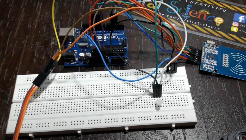
Once all of the components have been wired up, it’s time to fit all the components into a back box. Leave the two holes in the cover of the double back box for LED and a switch. Once you’ve connected them together, attach the RFID reader and servo motor to the outside with screws or strong double sided tape.
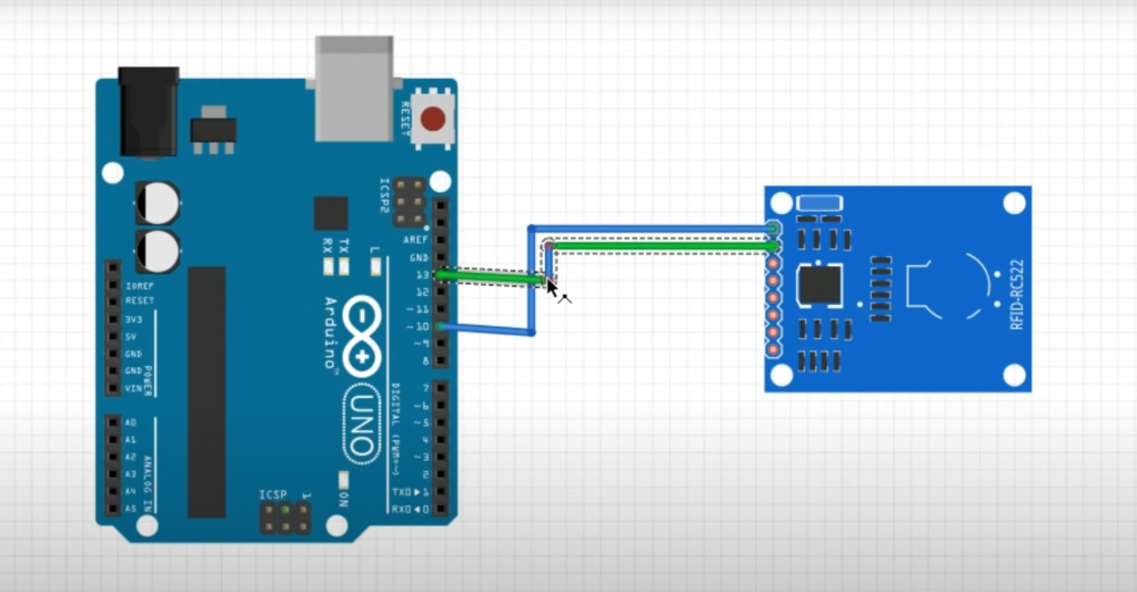
Finally, attach the device to the door lock with some screws.
Now that the hardware is assembled and connected, it’s time to set up the software. To do this, you’ll need to download additional libraries for Arduino and upload the code to the microcontroller. Then, you can connect your device with a Bluetooth app on your smartphone or tablet. The app will allow you to control the door lock from anywhere in range of the Bluetooth connection.
#include
#include
#include
#include
#include
#include
#define RST_PIN 9 // Configurable, see typical pin layout above
#define SS_PIN 10
#define Green_LED 6 //pin for green “door unlocked” indicator LED
#define Red_LED 7 //pin for red “door locked” indicator LED
String inputString = “”;
String command = “”;
String value = “”;
String password = “password”; // this is the password for opening and closing your door by Bluetooth
// you can set any password you like using digit and symbols
boolean stringComplete = false;
char array1[]=”Swipe To Unlock”; // the string to print on the LCD
char array2[]=” Door Locked “;
char array3[]=” Door Unlocked “;
char array4[]=” Locking “;
char array5[]=” Unlocking “;
char array6[]=” Accepted “;
char array7[]=” Swipe To Lock “;
int tim = 1; //the value of delay time
// initialize the library with the numbers of the interface pins
LiquidCrystal_I2C lcd(0x3F,16,2); // set the LCD address to 0x27 for a 16 chars and 2 line
MFRC522 mfrc522(SS_PIN, RST_PIN); // Create MFRC522 instance.
Servo myservo;
String read_rfid; // RFID tags ID
String ok_rfid_1=”c6ecd82b”;
String ok_rfid_2=”f5642a50″;
String ok_rfid_3=”4314622993c81″;
// String ok_rfid_4=”43ef222993c81″;
int addr = 1; // initialize eeprom address
int eVal = 0; // initialize value to be stored in eeprom
int lockPosition; // initialize lockPosition, used to value to sore in eVal
int servo_position;
int BUTTON1 = 8; // initialize the pin input of the lock/unlock button
void setup() {
Serial.begin(9600); // Initialize serial communications with the PC
while (!Serial);
SPI.begin();
mfrc522.PCD_Init();
inputString.reserve(50); // reserve 50 bytes in memory to save for string manipulation
command.reserve(50);
value.reserve(50);
boolean stringOK = false;
{
lcd.init(); //initialize the lcd
lcd.backlight(); //open the backlight
lcd.begin(16,2);
}
// sets pin modes input/output and lights led
pinMode(Green_LED, OUTPUT);
pinMode(Red_LED, OUTPUT);
digitalWrite(Green_LED, LOW);
digitalWrite(Red_LED, HIGH);
pinMode(BUTTON1,INPUT);
myservo.attach(5); // servo pin number
// sets initial locl position
lockPosition = EEPROM.read(1);
// Serial.print(EEPROM.read(1));
if(lockPosition == 1){
digitalWrite(Red_LED, LOW);
digitalWrite(Green_LED, HIGH);
}
else {
digitalWrite(Red_LED, HIGH);
digitalWrite(Green_LED, LOW);
lockUnlock();
}
swipeText();
}
/*
* Dump a byte array as hex values to Serial.
*/
void dump_byte_array(byte *buffer, byte bufferSize) {
read_rfid=””;
for (byte i = 0; i < bufferSize; i++) {
read_rfid=read_rfid + String(buffer[i], HEX);
}
}
void lockUnlock() { // locks or unlocks door
myservo.attach(5);
if(lockPosition == 1) {
lock1();
servo_position = 0;
myservo.write(servo_position);
digitalWrite(Red_LED, HIGH);
digitalWrite(Green_LED, LOW);
delay(2500);
lockPosition = 2;
eVal = lockPosition;
EEPROM.write(1,eVal);
// Serial.print(eVal);
}
else if(lockPosition == 2) {
lock2();
servo_position = 180;
myservo.write(servo_position);
digitalWrite(Red_LED, LOW);
digitalWrite(Green_LED, HIGH);
delay(2500);
lockPosition = 1;
eVal = lockPosition;
EEPROM.write(1,eVal);
// Serial.print(eVal);
}
myservo.detach();
}
void swipeText() // sends text to the lcd screen
{
if(lockPosition == 1){
lcd.clear(); //Clears the LCD screen and positions the cursor in the upper-left corner.
lcd.setCursor(0,0); // set the cursor to column 15, line 0
for (int positionCounter1 = 0; positionCounter1 < 15; positionCounter1++)
{
lcd.print(array3[positionCounter1]); // Print a message to the LCD.
delay(tim); //wait for 250 microseconds
}
lcd.setCursor(0,1); // set the cursor to column 15, line 1
for (int positionCounter = 0; positionCounter < 15; positionCounter++)
{
lcd.print(array7[positionCounter]); // Print a message to the LCD.
delay(tim); //wait for 250 microseconds
}
}
else if(lockPosition == 2){
lcd.clear(); //Clears the LCD screen and positions the cursor in the upper-left corner.
lcd.setCursor(0,0); // set the cursor to column 15, line 0
for (int positionCounter1 = 0; positionCounter1 < 15; positionCounter1++)
{
lcd.print(array2[positionCounter1]); // Print a message to the LCD.
delay(tim); //wait for 250 microseconds
}
lcd.setCursor(0,1); // set the cursor to column 15, line 1
for (int positionCounter = 0; positionCounter < 15; positionCounter++)
{
lcd.print(array1[positionCounter]); // Print a message to the LCD.
delay(tim); //wait for 250 microseconds
}
}
}
void lock1() // sends text to the lcd screen locking
{
lcd.clear();
lcd.setCursor(0,0);
for (int positionCounter1 = 0; positionCounter1 < 15; positionCounter1++)
{
lcd.print(array6[positionCounter1]);
delay(tim);
}
lcd.setCursor(0,1);
for (int positionCounter1 = 0; positionCounter1 < 10; positionCounter1++)
{
lcd.print(array4[positionCounter1]);
delay(tim);
}
}
void lock2() // sends text to the lcd screen for unlocking
{
lcd.clear();
lcd.setCursor(0,0);
for (int positionCounter1 = 0; positionCounter1 < 15; positionCounter1++)
{
lcd.print(array6[positionCounter1]);
delay(tim);
}
lcd.setCursor(0,1);
for (int positionCounter1 = 0; positionCounter1 < 12; positionCounter1++) { lcd.print(array5[positionCounter1]); delay(tim); } } void loop() { // checks for lock/unlock button press if(digitalRead(BUTTON1) == HIGH){ lockUnlock(); swipeText(); } if (stringComplete) { //Serial.println(inputString); delay(100); int pos = inputString.indexOf(‘=’); // value of pos variable > or = 0 means ‘=’ present in received string.
if (pos > -1) {
// substring(start, stop) function cut a specific portion of string from start to stop
// here command will be the portion of received string till ‘=’
// let received string is open=test123
// then command is ‘open’
command = inputString.substring(0, pos);
value = inputString.substring(pos+1, inputString.length()-1); // extract command up to \n excluded
if(!password.compareTo(value) && (command == “OPEN”)){
lockUnlock(); // call lockUnlock() function
Serial.println(” OPEN”); // sent open feedback to phone
delay(100);
swipeText();
}
if(!password.compareTo(value) && (command == “CLOSE”)){
// if password matched and command is ‘CLOSE’ than door should close
lockUnlock();
Serial.println(” CLOSE”); // sent ” CLOSE” string to the phone
delay(100);
swipeText();
}
if(password.compareTo(value)){
// if password not matched than sent wrong feedback to phone
Serial.println(” WRONG”);
delay(100);
swipeText();
}
}
// clear the string for next iteration
inputString = “”;
stringComplete = false;
}
// looks for rfid tag to be presented
if ( ! mfrc522.PICC_IsNewCardPresent())
return;
// Select one of the cards
if ( ! mfrc522.PICC_ReadCardSerial())
return;
dump_byte_array(mfrc522.uid.uidByte, mfrc522.uid.size);
// checks if an rfid tags ID matches the stored list, if so it will then lock or unlock the door
Serial.println(read_rfid);
if (read_rfid==ok_rfid_1) {
//ok, open the door.
lockUnlock();
swipeText();
}
//Add below as many “keys” as you want
if (read_rfid==ok_rfid_2) {
//also ok, open the door
lockUnlock();
swipeText();
}
//Add below as many “keys” as you want
if (read_rfid==ok_rfid_3) {
//also ok, open the door
lockUnlock();
swipeText();
}
}
void serialEvent() {
while (Serial.available()) {
// get the new byte:
char inChar = (char)Serial.read();
//Serial.write(inChar);
// add it to the inputString:
inputString += inChar;
// if the incoming character is a newline or a carriage return, set a flag
// so the main loop can do something about it:
if (inChar == ‘\n’ || inChar == ‘\r’) {
stringComplete = true;
}
}
}
FAQ
How do I program RFID with Arduino?
Yes, you can program RFID with Arduino. To do this, you need an RFID reader, a tag to read from, and the Arduino board itself. You also need a few components, such as resistors and LEDs, to help complete the circuit. Once your components are all connected up and ready to go, you can start programming the Arduino.
How to use RFID for projects?
This technology can be used in a variety of projects that rely on identifying items or people quickly and accurately. For example, you could use RFID to create an access control system for your home or workplace, or even make your own personalized security tags for valuable items.
How to make RFID door lock?
Making an Arduino RFID door lock is a great project for those looking to step up their DIY game. There are two main components necessary to complete the project: an Arduino board and a compatible RFID reader. Every time users wish to gain entry, they must place their RFID card near the reader for it to scan and authenticate. Once authenticated, the door will open automatically with a single swipe!
This is a rather simple project and can be completed with minimal technical know-how. To start, first assemble the components and connect them correctly. The Arduino board should be connected to the RFID reader with 4 wires – two for power, one for ground, and one for data transfer. Once connected, refer to your user’s manual on how to program the microcontroller.
Useful Video: How To Interface Rfid Module With Arduino || Tomson Electronics
Conclusion
Arduino RFID projects can provide an exciting way to explore and develop your skills in programming and electronics. With the many different components available, the possibilities are almost endless. Whether you want to monitor activity in a building, or control your own home security system, Arduino RFID projects can help you do it all. You may be able to use your project to create a more secure environment for residents or even help protect the environment by monitoring wildlife. Whatever your project may be, it’s sure to make an impact!
Thanks for reading our guide to Arduino RFID Projects! We hope you have found this information helpful in getting started with your own project. Be sure to check out our other resources including tutorials and code samples for inspiration on how to get even more out of your Arduino experience. Good luck!
References
- https://learn.sparkfun.com/tutorials/what-is-an-arduino/all
- https://www.watelectronics.com/arduino-projects/
- https://www.instructables.com/Windows-PC-LockUnlock-Using-RFID/
- https://www.instructables.com/RFID-Bluetooth-Door-Lock/







Leave a Reply