Accelerometers are electronic devices that utilize sensors to detect and precisely measure movement, orientation, and vibrations. They have become indispensable components in various applications, ranging from smartphones and video game controllers to drones. One notable example is the MPU6050 accelerometer, which stands out among other options due to its affordability and remarkable accuracy. Its widespread adoption in countless projects is a testament to its reliability and performance.
What is MPU6050?
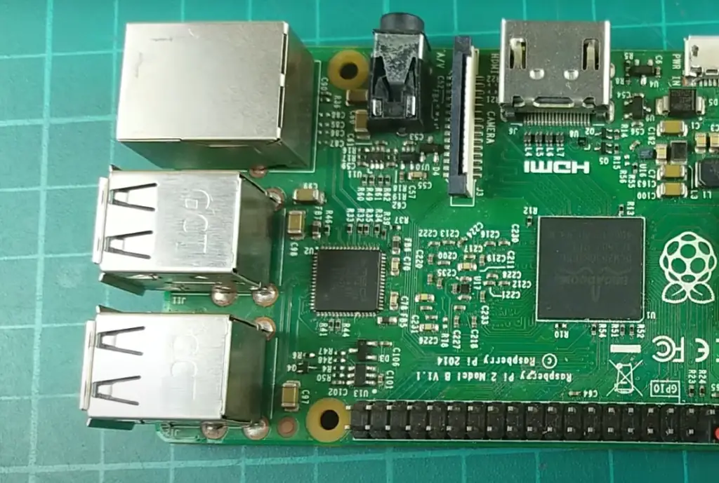
With its exceptional capabilities and comprehensive feature set, the MPU6050 stands as a top choice for developers and engineers seeking unparalleled motion tracking performance. [3]
MPU6050 Features and Specifications
The MPU6050 is a highly versatile sensor module that offers an extensive range of impressive features, making it an ideal choice for a wide variety of applications. Its key features include:
- Six-axis Motion Tracking: The MPU6050 combines a 3-axis accelerometer and a 3-axis gyroscope, enabling precise and accurate motion tracking capabilities. This allows for detailed measurement and analysis of various movements and orientations.
- Temperature Sensor: With an onboard temperature sensor, the MPU6050 can monitor environmental conditions with exceptional accuracy. This feature enables users to gather valuable data on temperature changes, which can be crucial in certain applications.
- Digital Motion Processor (DMP): The MPU6050’s integrated DMP feature offloads complex motion processing tasks from the main processor. By handling these tasks independently, the DMP significantly improves the overall system performance and frees up valuable resources for other operations.
- Built-in Analog-to-Digital Converter: Equipped with a high-resolution 16-bit ADC, the MPU6050 facilitates precise analog-to-digital conversion. This feature allows users to effortlessly incorporate analog sensors into their projects, expanding the range of possibilities and enhancing the sensor’s versatility.
- Low Power Consumption: With its efficient power management system, the MPU6050 boasts a low power consumption rate. This energy-efficient design makes it an excellent choice for battery-powered applications, ensuring prolonged operation without draining the power source excessively.
- Wide Operating Voltage Range: The MPU6050 operates within a broad voltage range of 2.375V to 3.46V, making it compatible with various microcontrollers and development boards. This versatility enhances its compatibility and ease of integration, simplifying the overall design process. [3]
With its comprehensive features and exceptional performance, the MPU6050 is a reliable and powerful sensor module that empowers developers to create innovative solutions across a wide range of applications.
Setting up the i2c bus on the Raspberry-pi
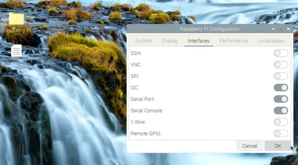
To utilize the MPU6050 accelerometer on a Raspberry Pi, you will need to enable communication via the i2c bus. The i2c (Inter-Integrated Circuit) bus is a popular serial communication protocol widely used in embedded systems and microcontrollers. To set up the i2c bus on your Raspberry Pi, follow these steps:
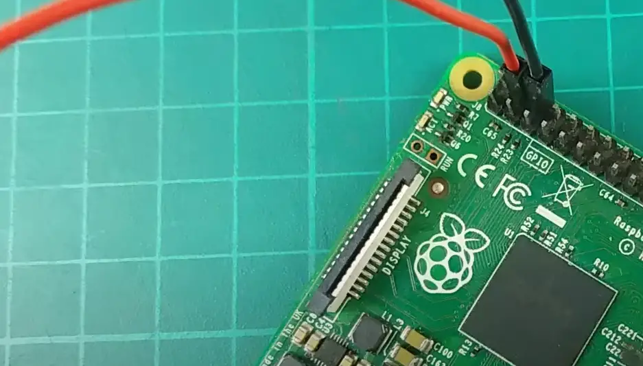
- Begin by connecting the MPU6050 to your Raspberry Pi using the appropriate pins. For specific pin connections, please refer to the datasheet for detailed information.
- Once your Raspberry Pi is booted up, open the terminal to proceed further.
- To install the i2c-tools package, enter the following command in the terminal: `sudo apt-get install -y python-smbus i2c-tools`. This will ensure that the necessary tools are installed for the i2c communication.
- To enable the i2c kernel module, you need to edit the /etc/modules file. Add the following line: `i2c-bcm2708`. This step allows the Raspberry Pi to recognize the i2c bus.
- After making the changes in the /etc/modules file, reboot your Raspberry Pi to apply the modifications.
- Once the Raspberry Pi has rebooted, enter the command `sudo i2cdetect -y 1` in the terminal. This command scans for connected devices on the i2c bus. If everything is set up correctly, you should see a device with the address 0x68, which is the default address of the MPU6050. [3]
With the i2c bus set up and communication established, you are now ready to access data from the MPU6050 on your Raspberry Pi. Take advantage of this connection to explore and utilize the features of the MPU6050.
Reading Acceleration Data on MPU6050
Power supply register PWR_MGMT_1 = 0x6B
The PWR_MGMT_1 register plays a crucial role in controlling the power modes and clock source of the MPU6050 sensor. By default, this register is set to 0x00, with all bits cleared, which effectively enables the internal 8MHz oscillator as the system clock. However, users have the flexibility to modify this setting by writing a different value to the register. For instance, setting the value to 0x80 will effectively put the device into sleep mode, conserving power and optimizing its functionality. [1]
Accelerometer configuration register ACCEL_CONFIG = 0x1C
The ACCEL_CONFIG register, a crucial component, allows users to fine-tune the range and sensitivity of the accelerometer to meet their specific needs. By default, it is initialized to 0x00, representing a full-scale range of ±2g. However, users can easily customize this value by writing a different one to the register, unlocking the potential for increased sensitivity and range. Additional options include ±4g, ±8g, and ±16g, offering a wider scope for precise measurements and enhanced control. [1]
Reading the Z-axis of the accelerometer
To read the Z-axis acceleration data of the MPU6050, follow these steps:
- Begin by setting up the i2c communication with the sensor, as discussed earlier.
- After establishing a connection, write to the ACCEL_CONFIG register and specify your desired range of sensitivity.
- Next, you will need to select an appropriate sampling rate for your application. The default sampling rate is 1kHz but can be adjusted by writing to the SMPLRT_DIV register.
- Once the sensor is configured, read the accelerometer data from the corresponding registers. In this case, you will need to read from the ACCEL_ZOUT_H and ACCEL_ZOUT_L registers, which store the high and low bytes of data, respectively.
With these steps, you can now successfully read the Z-axis acceleration data from the MPU6050 sensor. Use this method to extract data from other axes and explore its capabilities further. [1]
Sample rate configuration with SMPRT_DIV & CONFIG registers
The sampling rate of the MPU6050 can be configured using two registers: the SMPLRT_DIV and CONFIG registers. The SMPLRT_DIV controls the divider value for generating the sample rate, while the CONFIG register sets the digital low pass filter (DLPF) bandwidth and enables/disable temperature measurement. By modifying these values, users can adjust the sampling rate to meet their specific needs, making the MPU6050 an incredibly flexible and customizable sensor.
With its wide range of features and adjustable parameters, the MPU6050 accelerometer is an excellent choice for a variety of applications. Its ease of use, low power consumption, and versatile operating voltage make it a popular option among developers looking to incorporate motion sensing capabilities into their projects. Utilize its potential to create innovative solutions and take your projects to the next level. [1]
Configuration of the internal FIFO with FIFO_EN and USER_CTRL registers
The MPU6050 also features an internal FIFO (First In, First Out) buffer that can store up to 1024 bytes of data. This FIFO buffer is primarily used for storing raw sensor data and enables users to reduce the frequency of communication with the sensor, improving efficiency and performance. To configure the internal FIFO, two registers are used: the FIFO_EN register and the USER_CTRL register. The FIFO_EN register allows users to specify which sensor data they want to store in the FIFO buffer, while the USER_CTRL register enables/disables the FIFO buffer and resets it when necessary.
With its impressive capabilities and configurable features, using the MPU6050 accelerometer on Raspberry Pi opens up a world of possibilities for developers. Experiment with different settings, fine-tune its performance, and unlock its full potential to create innovative solutions. [1]
Reading MPU6050 data FIFO buffer
To read data from the MPU6050 FIFO buffer, follow these steps:
- Set up the i2c communication with the sensor and configure it according to your needs.
- Enable the internal FIFO by writing a value of 0x40 to the USER_CTRL register.
- Configure which sensor data you want to store in the FIFO buffer by writing a value to the FIFO_EN register. For instance, if you want to store accelerometer data, write a value of 0x08 to the register.
- Read from the FIFO count (FIFO_COUNT_H and FIFO_COUNT_L) registers to determine how many bytes of data are currently in the buffer.
- Finally, read from the FIFO buffer by repeatedly reading from its designated registers (FIFO_R_W). Each time data is read, the FIFO count will decrease by one until it reaches zero. [1]
With these steps, you can easily access the data stored in the MPU6050 FIFO buffer and process it accordingly.
Increase the i2c bus speed of the Raspberry-pi
To further optimize the performance of the MPU6050 accelerometer on Raspberry Pi, users can increase the i2c bus speed. By default, the i2c bus speed is set to 100kHz, but it can be increased up to 400kHz for faster and more efficient communication with the sensor. This can result in improved real-time data acquisition and enhanced responsiveness in applications that rely on accurate motion tracking.
To make this adjustment, follow these steps:
- Open the terminal and edit the boot config file by entering the command: sudo nano /boot/config.txt. This will open the configuration file in a text editor.
- Scroll down to the line that says “dtparam=i2c_arm=on” and add “,i2c_baudrate=400000” at the end. This additional parameter sets the desired i2c bus speed to 400kHz.
- Save the changes by pressing Ctrl + X, then Y to confirm. This will save the modified configuration file.
- Reboot your Raspberry Pi for the changes to take effect. This can be done by entering the command: sudo reboot.
By increasing the i2c bus speed, users can expect improved communication and faster data transfer between the Raspberry Pi and MPU6050 sensor. This can be particularly beneficial in applications that require real-time motion tracking, such as robotics, gaming, and gesture recognition. It is recommended to experiment with different speeds to find the optimal setting that suits your specific project needs and ensures reliable performance. [2]
Write a program in C to communicate with the mpu6050
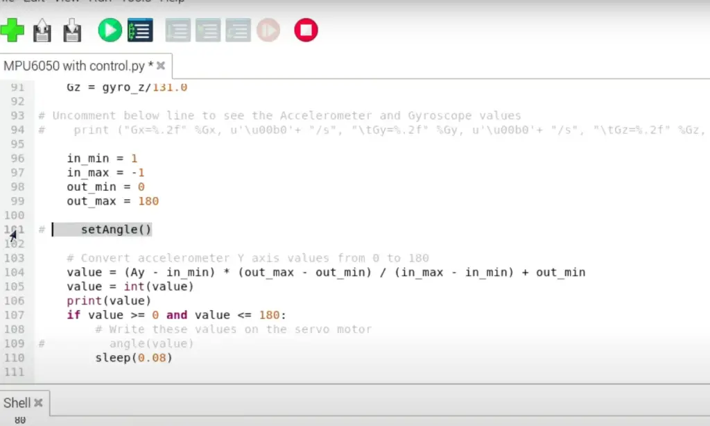
To demonstrate the communication between Raspberry Pi and MPU6050, here is a basic program written in C that reads accelerometer data from the sensor and prints it to the terminal:
“`
#include
#include
// Define i2c address for MPU6050
#define I2C_ADDR 0x68
int main()
{
int fd = wiringPiI2CSetup(I2C_ADDR); // Setup i2c communication
if(fd < 0) // Check for errors in setup
{
printf(“Error setting up i2c communication”);
return -1;
}
// Set accelerometer range to +/- 2g (config register)
wiringPiI2CWriteReg8(fd, 0x1C, 0x00);
// Enable accelerometer data to be stored in FIFO buffer (fifo en register)
wiringPiI2CWriteReg8(fd, 0x23, 0x08);
while(1)
{
int fifo_count = (wiringPiI2CReadReg8(fd, 0x72)<<8) | wiringPiI2CReadReg8(fd, 0x73); // Read fifo count if(fifo_count > 0)
{
int i;
for(i = 0; i < fifo_count; i+=6) // Read and print accelerometer data (fifo_r_w register)
{
int x = (wiringPiI2CReadReg8(fd, 0x74)<<8) | wiringPiI2CReadReg8(fd, 0x75);
int y = (wiringPiI2CReadReg8(fd, 0x76)<<8) | wiringPiI2CReadReg8(fd, 0x77);
int z = (wiringPiI2CReadReg8(fd, 0x78)<<8) | wiringPiI2CReadReg8(fd, 0x79);
printf(“Accelerometer Data: (%d,%d,%d)\n”, x,y,z);
}
}
}
return 0;
}
“`
FAQ
How to get acceleration from MPU6050?
To get acceleration data from the MPU6050 sensor, users can read the X, Y, and Z accelerometer registers (ACCEL_XOUT_H, ACCEL_XOUT_L, ACCEL_YOUT_H, ACCEL_YOUT_L, ACCEL_ZOUT_H, and ACCEL_ZOUT_L) and combine them to obtain the corresponding values in g-force. By default, the sensitivity range is set to +/- 2g, but it can be changed by writing a different value to the corresponding CONFIG register. Refer to the MPU6050 datasheet for more information on how to interpret the raw data read from these registers.
How does an accelerometer work in MPU6050?
The MPU6050 accelerometer uses a micro-electro-mechanical system (MEMS) to detect changes in acceleration along its three axes. It consists of tiny capacitive plates with fixed and movable electrodes. When the sensor experiences acceleration, these plates move relative to each other, causing a change in capacitance. This change is then converted into an electrical signal that can be read by the Raspberry Pi and processed to determine the magnitude and direction of acceleration. The MPU6050 also includes an integrated ADC (analog-to-digital converter) to convert these analog signals into digital data that can be easily interpreted by the microcontroller.
Is MPU6050 an accelerometer?
Yes, the MPU6050 is a 6-axis sensor that includes a 3-axis accelerometer and a 3-axis gyroscope. It combines these two sensors into one package for more compact and efficient motion tracking applications. The accelerometer in the MPU6050 can measure acceleration in all three dimensions (X, Y, Z) with a range of up to +/- 16g. It also includes features such as built-in temperature sensor and on-chip FIFO buffer for improved performance.
Is an MPU6050 a gyroscope or accelerometer?
The MPU6050 is both a gyroscope and an accelerometer. It combines these two sensors into one package for more accurate and efficient motion tracking. The gyroscope measures angular velocity along the three axes (X, Y, Z) while the accelerometer measures linear acceleration in the same directions. Together, they provide comprehensive information on how an object is moving in space.
What type of accelerometer is MPU6050?
The MPU6050 uses a MEMS-based accelerometer. This type of accelerometer is based on micro-electro-mechanical systems (MEMS) technology, which combines mechanical and electrical components on a microscopic scale to measure acceleration through changes in capacitance. This makes the MPU6050 compact, low-power, and highly sensitive compared to traditional accelerometers.
Is MPU6050 3.3 or 5?
The MPU6050 is a 3.3V device, meaning it operates using 3.3 volts for its power supply and communication with other devices like the Raspberry Pi. The I2C bus used to communicate with the sensor also operates at 3.3V, so it is important to ensure compatibility when connecting the MPU6050 to other components or microcontrollers. The sensor also includes voltage regulators for its internal components and can accept a range of input voltages from 2.375V to 3.46V.
Is MPU6050 discontinued?
No, the MPU6050 is not discontinued. It is still a widely used and popular sensor for motion tracking applications. In fact, it has been succeeded by newer versions such as the MPU9250 and MPU9255, which offer improved features and performance. However, the MPU6050 remains a reliable and cost-effective option for many projects that do not require advanced features.
Is an accelerometer the same as IMU?
No, an accelerometer is not the same as an IMU (Inertial Measurement Unit). An accelerometer measures linear acceleration, which is the rate of change of velocity in a straight line. On the other hand, an IMU combines multiple sensors, such as accelerometers and gyroscopes, to measure both linear and angular motion. This means that an IMU can provide information about not only how fast an object is moving in a straight line but also how it is rotating or changing direction.
Let’s take the MPU6050 as an example. It can be considered a 6-axis IMU because it includes both an accelerometer and a gyroscope in one package. The accelerometer measures linear acceleration, while the gyroscope measures angular velocity, which is the rate of change of angular displacement. By combining the information from these two sensors, the MPU6050 can provide a more comprehensive understanding of an object’s motion.
Useful Video: How to use the MPU6050 sensor module with Raspberry Pi board
Conclusion
The MPU6050 accelerometer is a versatile and powerful sensor that can be used for a variety of motion tracking applications. It offers many features such as low power consumption, built-in temperature sensor, and on-chip FIFO buffer to improve performance. By using the wiringPiI2C library, users can easily interface with the sensor and obtain accurate acceleration data from its three axes. With its compact size and affordable price, the MPU6050 remains a popular choice for projects that require motion tracking capabilities. So, go ahead and explore this sensor to add a new dimension to your Raspberry Pi projects! Remember, the possibilities are endless with the MPU6050 accelerometer. Happy experimenting!
References
- https://circuitdigest.com/microcontroller-projects/mpu6050-gyro-sensor-interfacing-with-raspberry-pi
- https://openest.io/en/services/mpu6050-accelerometer-on-raspberry-pi/
- https://microdigisoft.com/mpu6050-accelerometergyroscope-sensor-interfacing-with-raspberry-pi/




Leave a Reply