
When it comes to converting an AC signal to a DC signal, there are two main types of converters: half-bridge and full-bridge. Both have their own advantages and disadvantages, so which one is right for your project? In this article, we’ll answer some common questions about these two types of converters and help you decide which one is best for your needs. We’ll also provide some useful tips on how to choose the right converter for your application. So whether you’re a beginner or an experienced hobbyist, read on for all the information you need to make the right decision!
What is a Bridge Circuit?
A bridge circuit is an electrical circuit that connects two nodes by means of a path between them. The path may be direct or indirect, but it must have two endpoints. The most common type of bridge circuit is the Wheatstone bridge, which uses four resistors to connect two nodes. In addition, you might be interested in how to build a prototype electronic circuit article.
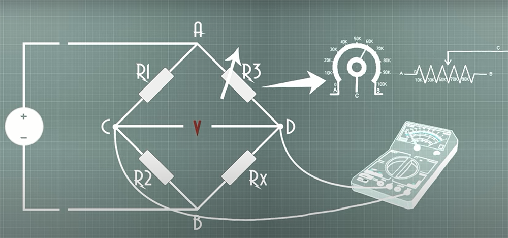
When electricity flows through a conductor, it encounters resistance. This resistance can cause the flow of electricity to slow down or stop altogether. Bridge circuits are used to overcome this problem by providing an alternate path for the current to flow around the resistor. [1]
What is a Bridge Converter?
Bridge circuits can be used in power converters to change the voltage or current in an electrical circuit. A bridge converter is an electronic circuit that changes direct current (DC) to alternating current (AC), or vice versa. The simplest form of a bridge converter consists of two switches, one connected to the positive side of the DC power source and the other connected to the negative side. When the top switch is turned on, current flows from the positive side of the power source through the switch to the load. When the bottom switch is turned on, current flows from the load back to the negative side of the power source.
Bridge converters are used in a wide variety of linear and non-linear uses, including AC/DC power supplies, DC/DC converters, and inverters. They are especially well-suited for use in high-power applications, such as motor control and welding.
Bridge converter typically consists of four diodes arranged in a bridge configuration, usually those include IGBTs, Bipolar transistors and MOSFETs. The diodes conduct current in only one direction, which allows them to convert AC to DC or vice versa.
The DPDT switch is used to control the direction of current flow through the load. When the switch is in the “on” position, current will flow from the positive terminal of the power source, through one of the MOSFETs, and into the load.
Bridge converters can be classified into two types: half-bridge converters and full-bridge converters. As their names imply, these two types of converters differ in the number of switches that are used. In a half-bridge converter, only two switches are used. This means that only two switches are used in the former, while full-bridge requires four. Half-bridge and full-bridge converters also differ in their voltage handling capability and cost.
The main difference between both converters is the number of switches required. Half-bridge converters only require two switches, while full-bridge converters require four. This means that half-bridge converters are simpler in construction and typically used in low power applications. Full-bridge converters are more complex but can handle higher power levels.
But what exactly is the difference between these two types of bridge converters? Let’s take a closer look. [2], [3], [4]
What is the Difference Between Half-Bridge and Full-Bridge?
A half-bridge converter is a variant of a bridge converter that uses two switches rather than four diodes. The two switches are connected to the both positive and negative of the DC power source respectively. When one switch is turned on, current flows from the positive side of the power source through the switch to the load. When the other switch is turned on, current flows from the load back to the negative side of the power source. Its main con is peak voltage, it’s half of the power source.
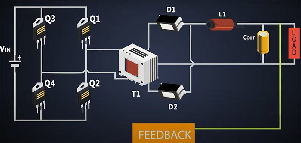
A full-bridge converter is a type of bridge converter that uses four switches instead of two. The four switches are connected to the positive and negative sides of both the power sources. This configuration allows for more efficient conversion between them. Full-bridge has no issues with peak voltage as it is the same as the voltage of the DC source. [2], [3], [4], [5]
Advantages of Half-Bridge
The Half-Bridge converter has its own set of differences. Let’s look at the advantages it has over the Full-Bridge variant first.
Lesser magnetic field emission
Starting off with the first advantage of this converter type, is the fact that it emits relatively lesser stray magnetic fields. This is due to the fact that there are only two semiconductor switches used in this type of converter as opposed to four in the full-bridge converter.
As we know, any kind of electric or magnetic field can be harmful if its intensity is high enough. Therefore, the lower emission of stray magnetic fields by Half-Bridge converters makes them a safer option compared to their full-bridge counterparts.
No gaps on magnetic path
Moving on to another advantage. Since there are only two switches, the magnetic path has no gaps. This results in low electromagnetic interference (EMI).
EMIs can potentially damage electronic equipment and cause electrical shocks. They can also disrupt radio and television signals. Low EMI is especially important in medical and aerospace applications.
Small magnetic cores are required
The transformer in a Half-Bridge Converter uses only two switches, which means that the magnetic cores required are smaller. This results in a reduction of size for the overall converter as well as weight.
In addition, the small habarites and minimum weight of Half-Bridge Converters make them well-suited for use in portable applications and portability is always an advantage.
Another advantage of using smaller magnetic cores is that they cost less than larger cores. Therefore, they are less expensive than Full-Bridge Converters. This cost advantage may be significant in some applications. [2], [3], [4], [5]
Disadvantages of Half-Bridge
Half-bridge converters are simple, efficient, and inexpensive. However, they do have some disadvantages.
Functions at half of the supply potential
The first disadvantage is that Half-Bridge Converters only function at half the supply potential. In other words, if the peak input voltage is 100V, the output voltage can only be 50V. This may not be an issue in some applications, but it is worth considering.
Not compatible with current mode control
Another disadvantage of Half-Bridge Converters is that they are not compatible with current mode control. Current mode control is a type of feedback control that uses the current through the switch, rather than the voltage across it, to regulate the output. This can be advantageous because it reduces switching losses and makes the converter more resistant to input voltage changes. However, since Half-Bridge Converters only use two switches, they cannot take advantage of this type of control. [2], [3], [4], [5]
Advantages of Full-Bridge
It has 4 switches
The full-bridge converter has four switches, which gives it some advantages over the half-bridge converter. This converter is more efficient than the half-bridge variant. This is because there are always two switches turned on in a full-bridge converter, whereas there is only one switch turned on in a half-bridge converter. When two switches are turned on, the converter can make use of both the positive and negative sides of the DC power source. This results in less wasted energy.
Have twice as much of voltage as Half-Bridge Converter
The main advantage of a full-bridge converter is that it can handle twice the voltage of a half-bridge converter. This is because the full-bridge converter uses four power switches instead of two. The extra switches allow the full-bridge converter to invert the polarity of the voltage, which effectively doubles the voltage that can be handled by the converter.
Widely used for high-voltage applications
Another advantage of the full-bridge converter is that it can be used in applications that require a high voltage. This is because the full-bridge converter can make use of both the positive and negative sides of the DC power source. The half-bridge converter, on the other hand, can only make use of one side of the power source. Because of this difference, a full-bridge converter is typically used in high-power applications, such as motor control and welding.
Has better power regulation
The full-bridge converter also has better power regulation than the half-bridge converter. This is because the full-bridge converter can regulate the output voltage by controlling the duty cycle of the switches. The half-bridge converter, on the other hand, can only regulate the output voltage by controlling the frequency of the switching. [2], [3], [4], [5]
Disadvantages of Full-Bridge
Despite the various advantages, there are also some disadvantages to using a full-bridge converter. Let’s take a look at them.
Price
First, full-bridge converters are more expensive than half-bridge converters because they require more components. Half-bridge uses only one active switch, while f-b uses two. This means that full-bridge converters are typically more complex and expensive to manufacture. So if you don’t really need the extra features that a full-bridge converter offers, then you might want to stick with the half-bridge converter.
They are harder to use
Second, f-b converters are more complex than half-bridge converters. This means that they are more difficult to design and build. If you’re not experienced in designing and building electronic circuits, then you might want to stick with the half-bridge converter.
They have the efficiency of 95%
Full-bridge converters have an efficiency of 95%. This means that they waste about five percent of the energy that they use. Half-bridge converters, on the other hand, possess an efficiency of 99%. So if you’re looking for the most efficient converter, then you should go with the half-bridge converter for your project.
They are noisy
Finally, f-b power converters can be quite noisy. This is because the converter uses four switches instead of two. The extra switches result in more electrical noise, which can be a problem in applications where noise is a concern. [2], [3], [4], [5]
How Does Full-Bridge Converter Work?
Full-bridge converters are the most popular type of power converters. They are simple, efficient, and can be used in a wide variety of applications. The full-bridge converter uses four switches to connect the input voltage to the output load. The transistor switches are controlled by a pulse-width modulation (PWM) signal. FB converters are incredibly versatile and can handle project that require a lot of power. [2], [3], [4], [5]
How Does Half-Bridge Converter Work?
As mentioned earlier, a half-bridge converter uses only two switches. One switch is connected to the positive side of the power source, and the other switch is connected to the negative side. The load is connected in between the two switches. When one switch is turned on, current flows from the power source through the switch to the load. When the other switch is turned on, current flows from the load back to the power source. [2], [3], [4], [5]
H-Bridge and What is It?
Before we conclude this article, we will mention another type of circuit that is worth mentioning, a H-bridge circuit. It shouldn’t be confused with Half-bridge. “H” in its name stands for the shape of the circuit when it’s drawn on a paper as it resembles a capital letter “H”.
H-bridge is a more complex converter that uses four switches. It can be used to control the direction of current flow. This makes it ideal for applications such as motor control, where you need to be able to change the direction of current flow.
H-bridge typically consists of a DPDT switch, diodes, and two N-channel MOSFETs attached to the low-voltage side of the circuit. The diodes are used to prevent the MOSFETs from conducting when they are not supposed to be, and the two-four N-channel MOSFETs are used to control the direction of current flow through the load.
The DPDT switch is used to control the direction of current flow through the load. When the switch is in the “on” position, current will flow from the positive terminal of the power source, through one of the MOSFETs, and into the load.
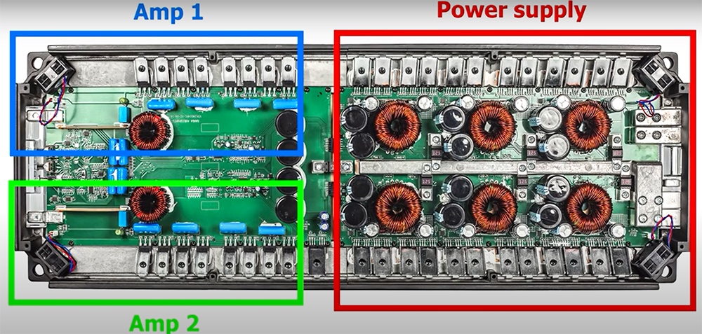
The H-bridge topology is also very flexible and can be used in a variety of different applications. It can even be used for audio power amplifiers! [6]
Check more articles to improve your experience in electronics:
- How to Test a Varistor?
- How is a Microprocessor Different from an Integrated Circuit?
- How to Stop Resistors Getting Hot?
FAQ
What is the purpose of a half bridge?
A half bridge is used to connect two loads in series or two power sources in parallel. It can also be used to create a voltage doubler or a current mirror.
Half-bridges are typically used in lower power applications where reversing the direction of current flow is not necessary. It is used in many applications such as DC-to-DC converters, electronic ballasts for fluorescent lamps, and class-D audio amplifiers.
What is a half bridge amp?
A half bridge amp is a type of amplifier that uses two transistors to amplify an input signal. The two transistors are arranged in a bridge configuration.
The first transistor is called the “polarity switch.” This transistor controls the flow of current through the second transistor, which is called the “amplifier.” The polarity switch turns the amplifier on and off. When the amplifier is turned on, it amplifies the input signal.
What is a full bridge?
A full bridge is a type of electrical circuit that allows current to flow in both directions between two pairs of conductors, as opposed to a half-bridge, which only allows current to flow in one direction.
Full bridges are often used in applications where it is necessary to reverse the direction of current flow, such as in AC motor control or rectification.
What is the main drawback of a half bridge inverter?
The main drawback of a half bridge inverter is that it cannot be used to produce a DC output voltage. This means that it can only be used for AC applications.
Another disadvantage of the half bridge inverter is that it has a lower power density than the full bridge inverter. This means that you need more space to install a half bridge inverter than you would for a full bridge inverter.
Is H-Bridge the same as half-bridge?
The term H-bridge is generally used to describe a full-bridge circuit, however, it can also refer to a half-bridge.
H-Bridge is a circuit of 4 switches that allows current to flow in both directions. The switches can be controlled so that the current flows in one direction or the other, or they can be turned off entirely. This makes H-Bridges useful for applications such as motor control, where you need to be able to change the direction of the current flowing through the motor.
Half-bridge is a circuit of only two switches that also allows current to flow in both directions. Basically, H-bridge is two half-bridges put together.
What is a full-bridge amplifier?
A full-bridge amplifier is an electronic amplifier that uses a bridge rectifier to supply power to the load.
A full-bridge amplifier has four transistors connected in series with the load. The transistors are arranged in a bridge configuration so that the current can flow through the load in both directions. Basically, it consists of two half-bridge amplifiers connected together.
Full-bridge amplifiers are typically used at high power levels and can be found in audio amplifiers, RF power amplifiers, and motor controllers.
What is a full-bridge driver?
A full-bridge driver is a device that can be used to control the current in a load, such as a motor. It consists of four MOSFETs arranged in a H-bridge configuration. The full-bridge driver can be used to control the speed and direction of a motor.
The four MOSFETs in a full-bridge driver are arranged in two pairs. The first pair is called the high side MOSFETs, and the second pair is called the low side MOSFETs. The high side MOSFETs are connected to the load, and the low side MOSFETs are connected to ground.
What is a full-bridge inverter?
A full-bridge inverter is an electrical device that converts direct current (DC) into alternating current (AC). It is a type of power inverter.
The main difference between a half-bridge and full-bridge inverter is the number of switches used. A half-bridge inverter uses two switches, while a full-bridge inverter uses four switches.
Full-bridge inverters are more efficient than half-bridge inverters because they can utilize the entire DC voltage swing, from 0 volts to the peak voltage.
What is the advantage of a half-bridge inverter?
The advantage of a half-bridge inverter is that it requires only two MOSFETs to operate. This reduces the overall cost and complexity of the inverter.
Another advantage of the half-bridge is that its winding has half the number of turns than a full-bridge. This results in a smaller, more compact transformer.
Can you bridge 2 different amps together?
No, you cannot bridge two different amplifiers together. The only way to do this would be to use a Y-cable that connects the two positive terminals of each amplifier together, and then connects the negative terminal of one amplifier to the ground. However, this will not work as intended because the impedance of the two amplifiers will not match and you will likely blow both amplifiers.
If you are looking to increase the power output of your system by adding another amplifier, you will want to look into running them in parallel. This can be done by connecting the positive terminal of one amplifier to the positive terminal of the other amplifier, and then connecting the negative terminals together. You will want to make sure that both amplifiers have identical gains, so that they both receive the same signal.
Doing this will effectively double the power output of your system while halving the impedance. This can be a great way to increase the volume of your system without having to invest in a new amplifier.
What is 4 ohm bridged?
Bridging a 4 ohm speaker for example, will put a 2 ohm load on each channel of the amplifier. This can be done by wiring two speakers in series on each side of the bridgeable amplifier. The benefit of bridging an amplifier is that it increases the power output while halving the impedance load on the amplifier.
Most amplifiers are stable down to a two-ohm load, but check your owner’s manual to be sure before bridging!
What is 8 ohm bridged?
Bridged mode is a configuration of two amplifiers (or occasionally more) connected together such that they operate as one amplifier, but with the added power made available by the additional amplifier or amplifiers.
Let’s take 8 ohms as an example. In bridged mode, you would need to draw a 4 ohm load to each amplifier to see the benefits of bridging. This results in a much higher power output than what either amplifier could produce by itself. Bridged mode is often used in professional audio applications where high power is required, and is extremely useful for subwoofers.
Useful Video: Full-bridge vs Half-bridge Amplifiers
Conclusion
That’s it for our introduction to bridge converters! We’ve looked at what they are, how they work and the difference between a half-bridge and full-bridge converter.
A half-bridge is a kind of circuit that uses two switches instead of four diodes. The full-bridge converter uses four switches and can handle more current than the half-bridge converter. Thanks for reading and happy conversion!
References:
- https://www.allaboutcircuits.com/textbook/direct-current/chpt-8/bridge-circuits/
- https://www.sunpower-uk.com/glossary/what-is-a-bridge-converter/
- https://www.rfwireless-world.com/Terminology/Advantages-and-Disadvantages-of-Full-bridge-converter.html
- https://www.rfwireless-world.com/Terminology/Advantages-and-Disadvantages-of-Half-bridge-converter.html
- https://circuitdigest.com/electronic-circuits/single-phase-half-bridge-and-full-bridge-inverter-circuit-using-matlab
- https://www.build-electronic-circuits.com/h-bridge/