
When designing and working with electronic circuits, understanding the standard lead spacing for capacitors is crucial. Lead spacing refers to the distance between the two leads of a capacitor, and it plays a significant role in determining how capacitors are mounted and connected on printed circuit boards (PCBs) or other electronic assemblies.
Standard lead spacing ensures compatibility and ease of use when integrating capacitors into circuits, facilitating proper placement, soldering, and electrical connections.
In this article, we will explore the common standards and recommended lead spacings for capacitors, providing valuable insights for engineers, hobbyists, and anyone working with electronic components.
What Are the Leads On a Capacitor?
These leads serve several crucial functions in the operation and installation of capacitors:
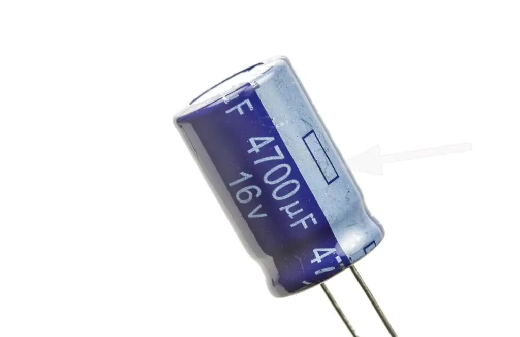
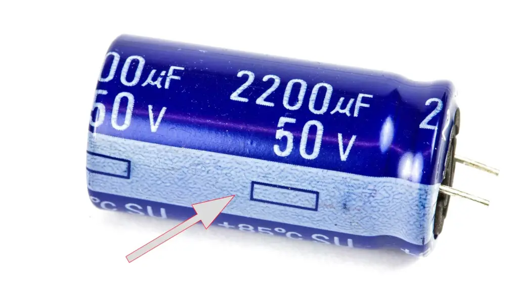
- Polarity: Unlike resistors, which are non-polarized and can be connected in either direction, most capacitors are polarized. The positive and negative leads indicate the correct orientation of the capacitor in a circuit. Connecting a polarized capacitor incorrectly can lead to malfunctions or even damage to the component or the circuit;
- Mounting: The leads provide a means to securely mount the capacitor onto a circuit board or into a socket. By inserting the leads into appropriate holes or soldering them onto designated pads, the capacitor becomes firmly connected to the circuit, ensuring reliable electrical contact;
- Electrical Connection: The leads are the physical connection points through which current flows into and out of the capacitor. When connected correctly, the positive lead allows current to enter the positive plate of the capacitor, while the negative lead allows current to exit the negative plate. This flow of charge enables the capacitor to store and release electrical energy as required by the circuit;
- Identification: The leads also aid in identifying the capacitance and voltage ratings of a capacitor. Capacitors often have markings or color-coding on the body, but the leads can provide additional confirmation of the correct value and specifications, particularly when the body markings are unclear or absent [1];
Does The Length of Capacitor Matter?
To understand the significance of capacitor length, it is essential to comprehend their construction. Capacitors consist of two conductive plates separated by a dielectric material. The capacitance, which determines the amount of charge the capacitor can store, depends on the surface area of the plates, the distance between them, and the dielectric constant of the material. The length of the capacitor is primarily associated with the area of the plates, and the width determines the separation between them.
In most cases, the length of a capacitor does not directly affect its capacitance. The capacitance is primarily determined by the surface area of the plates, with a larger area resulting in a higher capacitance. The length of the capacitor only influences the aspect ratio or the shape of the component.
However, it is important to note that changes in length can be accompanied by changes in other dimensions, such as width or thickness, which could impact the overall capacitance.
While the length of a capacitor may not directly affect its capacitance, it can have implications in certain scenarios. For example, in high-frequency applications, the physical length of the capacitor can contribute to parasitic inductance and affect its performance. Additionally, the length may impact the overall size and form factor of the capacitor, which could be significant in space-constrained designs.
Why The Lead Spacing Is Important For Capacitors?
The lead spacing of capacitors is important because it ensures that the electrical connections between the capacitor and other components are functioning properly.
Depending on the application, capacitors may have different lead spacings that are selected to meet specific requirements such as voltage rating, capacitance, and physical size. The lead spacing may also be chosen to comply with specific standards and regulations.
Proper lead spacing can help reduce the risk of short circuits, damage to the capacitor or other components and ensure reliable operation of the circuit. In addition, lead spacing can affect the electrical characteristics of the capacitor, including its capacitance, inductance, and impedance.
Therefore, it is important to choose the correct lead spacing based on the specific application and requirements.
What Is the Standard Lead Spacing for Capacitors?
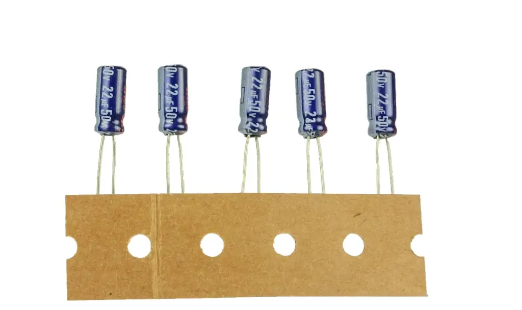
The standard lead spacing for capacitors can vary depending on the type and size of the capacitor. For small film radial capacitors, a standard lead spacing of 5mm is often used. However, for other types of capacitors, different lead spacings may be used.
For example, ceramic disk capacitors may have lead spacings of 7.5mm or 10mm, and wound capacitor technology may use lead spacings of 10mm to 37.5mm [2].
In general, the lead spacing is selected based on the specific requirements of the application and may be chosen to comply with specific standards or regulations.
Do You Need to Extend Capacitor Leads?
Whether or not you need to extend capacitor leads depends on the specific requirements of your application. In some cases, it may be necessary to extend capacitor leads to properly install a capacitor within a circuit.
However, it is generally recommended to keep the leads as short as possible to ensure optimal performance and reliable operation of the circuit. If you do need to extend capacitor leads, it is important to do so carefully and use appropriate techniques to ensure reliable electrical connections and prevent damage to the capacitor or other components.
It may also be necessary to use heat shrink or other types of insulation to protect the extended leads and prevent them from coming into contact with other components.
How Do You Extend a Capacitor Lead?
Extending a capacitor lead can be done using various methods, depending on the specific application and requirements.
One common method is to solder an additional length of wire to the existing lead, being careful to ensure a reliable electrical connection. It is important to use the proper gauge of wire that can handle the required current and voltage levels and to use appropriate techniques to prevent damage to the capacitor or other components.
Another method is to use a jumper wire or PCB trace to connect the capacitor to other components in the circuit.
Rules For The Placement Of Components On The PCB:
Group Components by Function
Grouping components by function helps organize the circuit and improves the overall layout. Components that are closely related in their operation or interact with each other should be placed in proximity to minimize trace lengths and signal interference. By grouping components logically, it becomes easier to understand and troubleshoot the circuit during the design and testing phases.
Use a Standard Orientation for the Components
Maintaining a consistent orientation for components simplifies the assembly process and reduces errors. Standardizing the orientation also aids in identifying components and ensures that the PCB is aesthetically pleasing and easy to read. Most components have a designated pin 1 or polarity indicator that should be aligned consistently across the board.
Separate the Different Areas from Each Other
Separating different areas of the PCB helps prevent signal interference and minimizes cross-talk between components or functional blocks. High-power components, high-frequency circuits, and sensitive analog or digital components should be isolated to avoid electromagnetic interference (EMI) and improve signal integrity.
Keep the Components Away from Heat Sources
Heat sources, such as power devices or voltage regulators, should be placed strategically to prevent heat accumulation and potential damage to other components. Thermal considerations are particularly important for components sensitive to temperature variations. Adequate spacing and thermal vias can be used to dissipate heat effectively and maintain a stable operating temperature for all components [3].
Create Solid Ground Planes
Solid ground planes serve multiple purposes, including providing a low-impedance return path for signals, reducing noise, and improving electromagnetic compatibility (EMC). Placing components over a continuous ground plane helps minimize the loop area of high-frequency signals and reduces the risk of signal degradation or EMI issues.
What to Place Near the Edges of the PCB
The edges of the PCB are crucial for connectivity, mounting, and mechanical stability. Key components that require external connections or connectors, such as power input, data interfaces, or user interfaces, should be placed near the board edges. This arrangement simplifies cable routing, reduces trace lengths, and improves accessibility during assembly and maintenance.
Leave Enough Space for the Traces
Sufficient spacing between components allows for proper routing of traces, especially for high-speed signals. Signal integrity and impedance control can be compromised if traces are routed too closely or have inadequate clearance. Adequate spacing also ensures ease of assembly, testing, and rework if required.
Designing for Manufacturability, Accessibility, and Maintenance
Considerations for manufacturability involve placing components in a way that facilitates automated assembly processes, such as pick-and-place machines. Components should be positioned to allow access for testing and debugging during the manufacturing and maintenance phases. Accessibility to critical components, such as microcontrollers or programming headers, should be prioritized for programming or firmware updates.
High-Speed Signals
For high-speed signals, careful attention must be given to trace lengths, impedance matching, and signal integrity. Placing critical high-speed components near each other and using controlled impedance traces help minimize signal degradation, reflections, and timing issues. Signal paths should be kept as short as possible, avoiding unnecessary bends or vias.
Thermal Management
Efficient thermal management is crucial for maintaining component reliability and performance. Heat-generating components should be placed to allow proper airflow and heat dissipation. Heat sinks, thermal vias, and adequate spacing between components can help dissipate heat effectively. Additionally, sensitive components may require thermal pads or vias to transfer heat away from their immediate vicinity.
FAQ:
1. How many leads does a capacitor have?
Most capacitors have two leads, commonly referred to as the positive (+) and negative (-) leads. These leads are typically metal terminals extending from the body of the capacitor [4].
2. Why do some capacitors have 3 leads?
Some capacitors, particularly those with adjustable capacitance, may have three leads. The additional lead is often a wiper or a center tap, allowing for variable capacitance by adjusting the contact between the wiper and the main capacitor plates. These types of capacitors are commonly known as trimmer or variable capacitors.
3. How many terminal leads does a capacitor have?
A capacitor typically has two terminal leads. These leads are used for connecting the capacitor into an electronic circuit, allowing the flow of current into and out of the component.
4. Why do some capacitors have 4 leads?
This configuration allows for the use of two capacitors in a single package, providing convenience and space-saving benefits in certain applications.
5. What is the 2-3 rule of capacitor placement?
The 2-3 rule of capacitor placement refers to the guideline of placing decoupling capacitors close to the power pins of integrated circuits (ICs) [5]. The rule suggests placing at least two capacitors – one smaller and one larger in value – within 2 mm of the power pin and 3 mm of each other. This helps minimize inductance in the power supply path and provides localized energy storage for the IC, reducing noise and improving performance.
6. Why does capacitor current lead by 90°?
In an AC (alternating current) circuit, the current in a capacitor leads the voltage by 90 degrees. This phase shift occurs because the charging and discharging of the capacitor depend on the rate of change of the voltage across it. As the voltage increases, the capacitor charges, causing the current to flow. However, it takes time for the current to reach its maximum value, resulting in the phase shift of 90 degrees.
7. What is optimal capacitor placement?
Optimal capacitor placement involves considering various factors, such as minimizing trace lengths, reducing loop area, and ensuring proximity to the components they serve. Placing capacitors close to the components that require decoupling or filtering helps minimize parasitic inductance and resistance in the circuit, improving performance and reducing noise.
8. What could happen if you touch both capacitor leads at the same time?
If you touch both capacitor leads simultaneously, and the capacitor is charged, you can receive an electric shock. The stored energy in the capacitor can discharge through your body, potentially leading to injury or discomfort. It is important to discharge capacitors and exercise caution when handling them to avoid accidental shocks.
9. Can you keep a 1-farad capacitor in the cupboard or to a sphere?
A 1-farad capacitor is a relatively large capacitor and is not typically used in household applications. However, if you have a 1-farad capacitor, it is generally not advisable to store it in a cupboard or confined space. Capacitors should be stored in a cool, dry, and well-ventilated area to prevent damage or degradation. Additionally, it is important to follow manufacturer guidelines and safety precautions when handling and storing capacitors.
10. How many leads does a capacitor have?
As mentioned earlier, most capacitors have two leads—a positive (+) lead and a negative (-) lead. These leads provide the connection points for the capacitor in an electronic circuit. However, it is important to note that there are exceptions, such as capacitors with additional leads for specialized applications.
Useful Video: Failing RIFA safety capacitors
References
- https://www.electronicstalk.org/what-is-the-standard-lead-spacing-for-capacitors/
- https://forum.digikey.com/t/lead-spacing-bending/435
- https://www.edaboard.com/threads/what-lead-spacing-do-you-use-for-radial-capacitors-on-pcbs.266712/
- https://www.madbeanpedals.com/forum/index.php?topic=24900.0
- https://www.proto-electronics.com/blog/best-rules-for-pcb-components-placement