
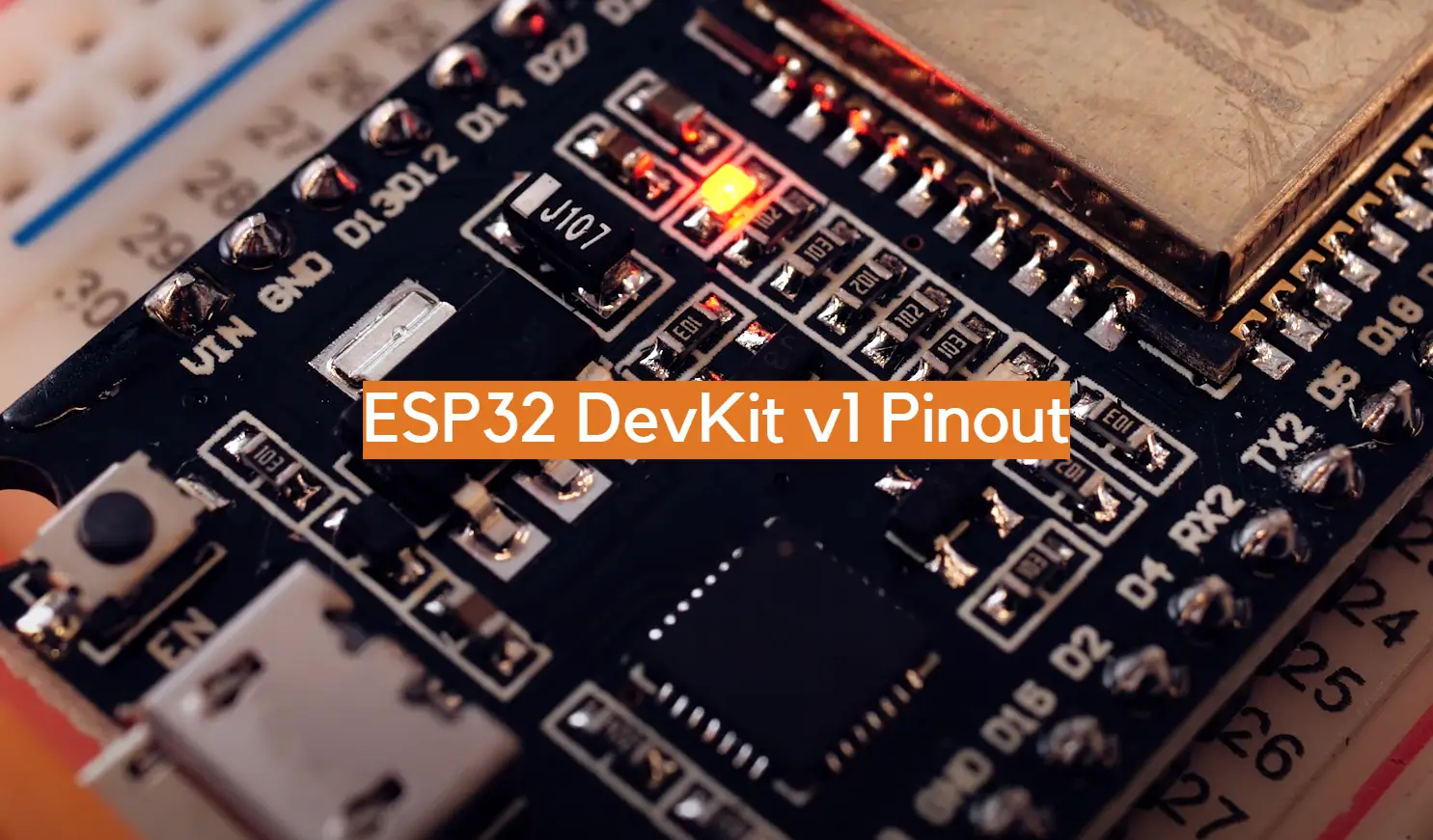
The ESP32 DevKit v1 is a powerful development board that lets you build complex projects with ease. This article provides a comprehensive overview of the ESP32 DevKit v1 pinout, including a detailed explanation of each pin and its function. We’ll also provide some useful tips on how to get the most out of this board. So, whether you’re just getting started with the ESP32 or you’re looking for some more advanced tips, read on for all the information you need!
ESP32 Boards in General
It has built-in Wi-Fi and Bluetooth connectivity, allowing complex Internet of Things (IoT) applications to be implemented quickly and easily. The ESP32’s integrated dual-core processor allows it to handle multiple tasks at once, making it an ideal choice for applications that require simultaneous computing with low latency. Additionally, the ESP32 comes with a large number of peripheral options such as I2C, SPI, UARTs, ADC/DACs, PWM outputs, and various GPIO pins for custom hardware connections. This makes it easy for users to connect their own sensors or other external devices to the board for their applications.
The ESP32 boards come in a variety of sizes, shapes and form factors to suit different projects and applications. Some common features include USB ports for programming and debugging, onboard LEDs and buttons, inbuilt debuggers/emulators, on-board memory storage – both RAM and flash, JTAG headers (for advanced debugging), as well as micro SD cards slots. Additionally, some ESP32 boards have additional components such as temperature sensors, motion sensors or RFID readers that can be used to extend their capabilities even further. These added features make the ESP32 ideal for use in wearable technology or other connected devices.
The ESP32 contains 48 pins in total with 25 of them being broken out to the pin headers on both sides of the development board. These include: 15 ADC channels with ranges of 0-1V, 0-1.4V, 0-2V, or 0-4V, 2 UART interfaces, 25 PWM outputs, 2 DAC channels, three SPI, I2C and I2S interfaces and 9 Touch Pads. Now let’s discuss each of these in total. [1]
ESP32 DevKit v1 GPIO Pins
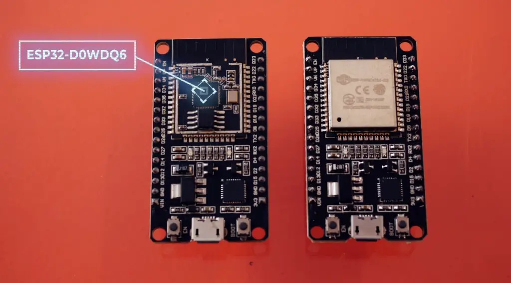
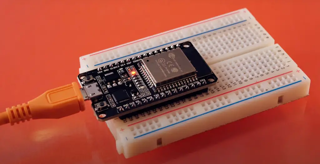
The DevKit v1 comes in two versions; one with USB connection for easy programming and debugging, and another without USB that can be used to make compact projects. If you’re just starting out, you might be confused by the many pins and components of the board. To make things easier, here’s a comprehensive guide to the ESP32 DevKit v1 pinout.
We shall start with GPIO pins. GPIO stands for General-Purpose Input/Output pins and are used to send digital signals between the ESP32 and other connected devices. GPIOs include a wide range of functions such as reading sensors, controlling motors or displaying information on LCD screens. The DevKit v1 has 25 GPIOs broken out to both sides, each of which can be assigned different functions by programming the appropriate registers. There are several kinds of GPIOs: digital-only, analog-enabled, capacitive-touch-enabled, etc. Not only can Analog-enabled GPIOs and Capacitive-touch-enabled GPIOs be configured as digital ones, but also they are able to have an internal pull-up or a pull-down set up. Furthermore, these same digital GPIOs may also be transformed into high impedance devices if desired.
Each of the pins has its uses. Four of the GPIO pins are input only which means they can only be used for reading information, these are GPIOs 34, 35, 36 and 39. There are also pins that can be used with an I2S (Inter-IC Sound) audio interface to send or receive digital audio signals. Finally, there are 8 pins that we don’t suggest using as they are either reserved for external components or have special functions related to booting up the board. These include: GPIO 1, 6, 7, 8, 9, 10 and 11.
Below we will break down the GPIO pins into 3 categories: Analog-enabled Pins, Digital Pins and Special Function Pins.
ESP32 DevKit v1 ADC Pins
ADC pins in the ESP32 DevKit v1 are Analog to Digital Converters which allow analog signals to be converted into digital values. ADC pins can be used with several different types of sensors, such as temperature sensors, light sensors, humidity sensors and more.
GPIO PinsESP32 DevKit v1 has two analog to digital converters (ADC) on 15 channels. With ADC pins, external voltages from 0 to 3.3V (operating voltage) can be converted into integer values ranging from 0 to 4095; giving a resolution of 0.0008 volts per unit or an impressive .8 mV accuracy. ADC Pins also have internal pull-up resistors, allowing them to be connected directly to switches or other devices that operate at low voltages.
The ADC pins are labeled ADC_CHX and can be found on GPIOs 2, 4, 12, 13, 14, 15, 25, 26, 27, 32, 33, 34, 35, 36 and 39. It’s worth mentioning that ADC2 pins cannot be used with Wi-Fi on the ESP32 DevKit v1, as the Wi-Fi module also uses the ADC2 pins.
ESP32 DevKit v1 DAC Pins
DAC pins are used for Digital-to-Analog conversion, allowing digital signals to be converted into analog signals. ESP32 DevKit v1 has two 8-bit DACs (Digital-to-Analog Converters) which can be used to output analog voltage levels from 0 to 3.3V. This is useful for connecting the ESP32 board to devices that require an analog signal, such as sensors or motors.
The DAC pins on the ESP32 DevKit v1 are labeled ‘GPIO25’ and ‘GPIO26’. To use the DAC, you must first configure one of these pins with a specific pin mode using the gpio_pad_select_gpio() function in your code.
ESP32 DevKit v1 SPI Pins
SPI, short for Serial Peripheral Interface, is an electrical serial communication protocol between two devices. It’s commonly used to connect microcontrollers and other peripheral components like sensors, displays, and storage units.
The ESP32 DevKit v1 board has a total of three SPI pins: SPI, HSPI, and VSPI. All SPIs support 4 timing modes of the SPI format transfer, up to 80 MHz and the divided clocks of 80 MHz and up to 64-Byte FIFO. Keep in mind that out of these only VSPI and HSPI are usable SPI ports on the ESP32. The GPIO pin layout for these are GPIO 2, 5, 12, 13, 14, 15, 18, 19, 2023.
ESP32 DevKit v1 I2C bus
The two wires are a Serial Data Line (SDA) and Serial Clock Line (SCL), allowing multiple devices to communicate with each other while sharing the same clock signal. As long as only one device on the bus is transmitting data, all other devices can listen and process that data.
The ESP32 is outfitted with a single I2C bus that can support up to 112 sensors and peripherals. The SDA and SCL pins are, by default, connected to specific pins; yet you have the choice of bit-banging your own protocol on any GPIO pin using the command wire.begin(SDA, SCL).
ESP32 DevKit v1 UART pins
The ESP32 development board features two UART interfaces – UART0 and UART2 – that can support high-speed asynchronous communication, including RS232 and RS485, IrDA up to an incredible 5 megabit per second rate!
ESP32 DevKit v1 Touch Pins
The Touch Pins are one the most important and versatile pins on the board as it allows you to use touch input for your projects. The ESP32 DevKit v1 has 9 capacitive touch-sensing GPIOs
The Touch Pin consists of three distinct parts – The Sensor Pad, The Interrupt/IO pin and The Digital IO Pin.
The Sensor Pad is the main part of the touch pin which is sensitive to finger touches and near proximity. It acts as an antenna that detects changes in capacitance when a finger or other conductive material approaches it. This information is then sent to the Interrupt/IO pin, which triggers an interrupt whenever there is a change in capacitance.
The Digital IO Pin acts as an output for the Touch Pin and can be used to control other components or peripherals based on the input from the Sensor Pad. For example, you could use it to switch on a light or activate an alarm after detecting a finger touch.
RTC GPIO Pins DevKit v1 Touch Pins
ESP32 GPIOs that are routed to the RTC low-power subsystem are known as RTC GPIOs. These pins are utilized when the Ultra Low Power (ULP) co-processor is active, in order to wake ESP from deep sleep mode.
ESP32 DevKit v1 Power Pins
As for power pins, the ESP32 DevKit v1 has two options: the VIN pin and the 3V3 pin. The VIN pin provides both the ESP32 and peripherals with their power source, but only when you have a regulated 5V supply. And, the 3V3 pin’s voltage regulator output can generate up to 600mA! And let’s not forget GND – your all-important ground connection point. [2], [3]
FAQ
Is ESP32 better than Arduino?
The ESP32 and Arduino are both popular development boards, but they serve different purposes. While the Arduino is a general-purpose microcontroller board that can be used for many different applications, the ESP32 is designed specifically for Wi-Fi and Bluetooth Low Energy (BLE) connectivity.
Arduino is popular because it offers an easy way to program and control electronic components. However, its limited memory and processing power means it can’t keep up with more complex tasks like providing reliable and secure wireless connections. The ESP32 has greater RAM capacity and faster processing speeds than the Arduino, allowing it to tackle these types of tasks with ease. Additionally, the ESP32 has built-in support for various communication protocols like Wi-Fi and BLE, making it an ideal choice for IoT (Internet of Things) applications.
In short, the ESP32 is better than Arduino when it comes to wireless connectivity, memory capacity, and processing power. The ESP32 is specifically designed to enable fast and secure communication between different devices over a network, while Arduino was built with general-purpose use in mind. Therefore, depending on your project’s requirements, one board may be more suitable than the other.
What is ESP32 used for?
The ESP32 is a powerful and versatile microcontroller that can be used for a variety of tasks. It’s great for connecting to the Internet, controlling devices, or creating projects like home automation systems, IoT devices, wearables, robotics, smart grids, etc.
The ESP32 is an inexpensive yet powerful processor with WiFi and Bluetooth Low Energy (BLE) capabilities built in. These features make it ideal for applications ranging from simple remote control to complex connected systems.
The ESP32 DevKit v1 pinout allows developers to quickly develop their desired project by simply connecting it to any compatible device. It has 30 pins in total, allowing developers to utilize the full capabilities of the ESP32 processor.
By using the ESP32 DevKit v1 pinout, developers can take advantage of many features and capabilities offered by this microcontroller that allows them to design complex projects quickly and easily.
How many pins does ESP32 DevKit V1 have?
The ESP32 DevKit V1 has a total of 30 pins, consisting of 25 GPIO pins, two ADCs (Analog to Digital Converters), two DACs (Digital to Analog Converters), three SPI pins, a single I2C (Inter-Integrated Circuit) and two power pins. Finally there’s an enable pin used to enable ESP32.
What language does ESP32 use?
The ESP32 uses the popular programming language C/C++ to program applications and has ports of Python, MicroPython, and JavaScript available. Additionally, the ESP-IDF (IoT Development Framework) software development framework is available for developing apps with the ESP32. The ESP-IDF enables writing programs in C/C++ and provides a comprehensive set of libraries that make it easier to program hardware components such as sensors, displays, communication modules, ADC/DACs and more.
Is ESP32 an IoT device?
Yes, ESP32 is an Internet of Things (IoT) device. It is a powerful microcontroller with integrated Wi-Fi and Bluetooth connectivity that can be used to develop IoT applications. The ESP32 has Wi-Fi, which means it can handle 2.4GHz frequencies. It also includes several dedicated hardware interfaces for communication including I2C, UART, SPI, CAN and PWM. With its low power consumption, ESP32 makes IoT development much easier and more affordable than ever before.
Useful Video: DOIT ESP32 DEVKIT V1 ESP-WROOM-32 ESP32 ESP-32S Development Board
Conclusion
ESP32 DevKit v1 is a popular and affordable development board with a wide range of applications. As the successor to ESP8266, it has many edge computing capabilities and is suitable for projects such as home automation and Internet of Things (IoT). As an open-source platform, it offers great flexibility for customizations and comes with several built-in sensors that can be used in various ways. The pinout of the DevKit v1 makes sure that you are able to connect all the components together properly, so you can make full use of its potential.
In this guide, we have discussed the basic features of ESP32 DevKit v1 and explored its pinout in detail. We also discussed some common questions about using this board and provided useful tips for getting the most out of it. If you are still new to the ESP32 platform, this guide will put you on the right track for a successful project.
Happy coding!
References
- https://catalog.us-east-1.prod.workshops.aws/workshops/5b127b2f-f879-48b9-9dd0-35aff98c7bbc/en-US/module1/esp32
- https://lastminuteengineers.com/esp32-pinout-reference/
- https://randomnerdtutorials.com/esp32-pinout-reference-gpios/