
Resistors are fundamental components in electronic circuits, providing control over the flow of electric current and voltage. Whether you are a beginner or an experienced electronics enthusiast, understanding how to wire resistors correctly is essential for building and troubleshooting circuits.
In this article, we will cover the basics of resistor wiring, including the different types of connections, the significance of resistor color codes, and techniques for calculating resistance values.
By the end of this guide, you will have the knowledge and confidence to wire resistors accurately and ensure the optimal performance of your electronic projects. So, let’s dive in and unravel the secrets of resistor wiring!
About Wire Wound Resistors:
Structure of Wire Wound Resistor
Wire wound resistors consist of a resistive wire wound around a ceramic or fiberglass core. The resistive wire used is typically made of alloys such as nichrome or constantan, which have high resistivity. The wire is wound in a precise pattern to achieve the desired resistance value. The winding is then coated with an insulating material, such as enamel or silicone, to protect it from environmental factors and ensure electrical insulation [1].
Types of Wire Wound Resistors
There are several types of wire wound resistors available, including:
- Power Wire Wound Resistors: These resistors are designed to handle high power levels and are commonly used in applications that require high current and voltage ratings;
- Precision Wire Wound Resistors: These resistors are manufactured with high accuracy and low tolerance values. They are commonly used in precision measurement equipment and circuits that demand precise resistance values;
- Variable Wire Wound Resistors: These resistors have a movable wiper that allows the user to adjust the resistance value within a specified range. They are frequently used in applications requiring adjustable resistance, such as volume control in audio systems;
Production of Wire Wound Resistor
The production process of wire wound resistors involves several steps. It begins with the selection of appropriate resistive wire and core material. The wire is then wound around the core using automated winding machines that ensure precision and consistency. After winding, the resistor is subjected to heat treatment to stabilize the resistance value and eliminate any internal stresses. Finally, the resistor is coated with an insulating material and undergoes testing for quality assurance.
Working Principle
When current flows through the resistive wire, it encounters resistance, which leads to the generation of heat. The resistive wire’s material and dimensions determine the resistance value and power handling capability of the resistor. The heat dissipation capability of wire wound resistors is typically enhanced by their large surface area, which allows efficient transfer of heat to the surrounding environment.
The Role of Wire Wound Resistors
Wire wound resistors play a crucial role in electronic circuits. They are primarily used to limit current flow, divide voltage, and provide a precise resistance value. Their high power-handling capability makes them suitable for applications involving high current and voltage levels. Wire wound resistors also help in stabilizing circuits by dissipating excess energy as heat, thereby protecting sensitive components from damage.
Applications
Wire wound resistors find applications in various industries and electronic devices, including:
- Power Electronics: They are used in power supplies, motor control circuits, inverters, and frequency converters;
- Automotive Electronics: Wire wound resistors are employed in automotive ignition systems, electric vehicle controllers, and electronic braking systems;
- Industrial Equipment: They are utilized in industrial control systems, machine tools, and high-power resistive load banks;
Detection Method and Replacement of Wire Wound Resistor
To detect a faulty wire wound resistor, you can measure its resistance using a multimeter. If the measured resistance deviates significantly from the specified value or shows an open circuit, it indicates a defective resistor. In such cases, replacement is necessary to restore proper functionality to the circuit.
When replacing a wire wound resistor, it is crucial to choose a resistor with the same or higher power rating and resistance value. The physical dimensions and package type should also match the original resistor to ensure proper fit and compatibility. Soldering techniques should be employed carefully to avoid overheating and damaging nearby components.
How To Wire A Resistor?
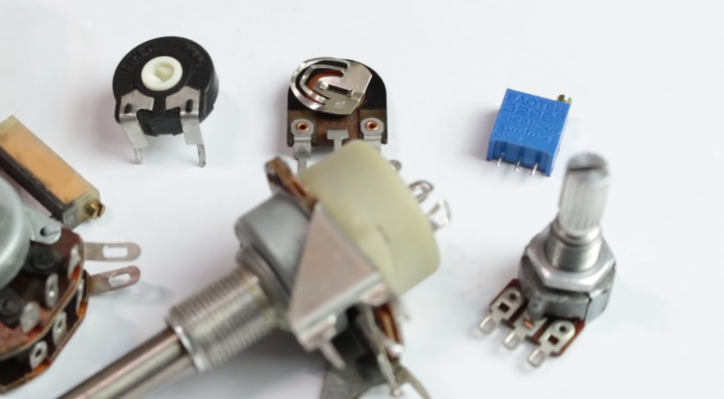
Wiring a resistor might seem like a daunting task at first, but it’s actually quite simple. A resistor is an electrical component designed to restrict the flow of current in a circuit. They are available in various shapes, sizes, and resistance values to suit different applications. If you’re working on a project that requires the use of resistors, here’s how you can wire them.
The first step is to identify the resistor’s color code. Resistors are color-coded to indicate their resistance value, tolerance, and wattage rating. You can use a resistor color code chart to decode the colors on the resistor. Once you have determined the resistance value, you can select the appropriate resistor for your circuit.
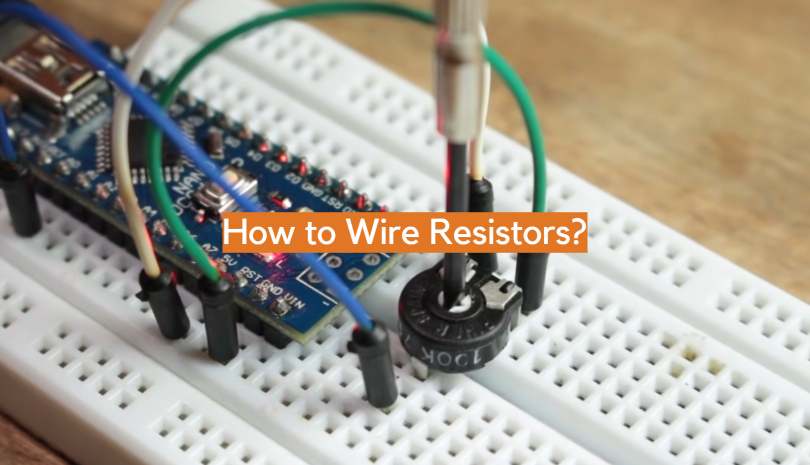
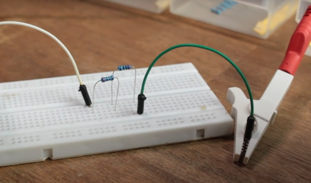
Now, connect the resistor to the circuit. Resistors usually have two leads, which are the metal wires extending from each end of the cylinder. The leads should be inserted into the circuit board or breadboard, so they make a physical connection with the other components. Be sure to place the resistor in the right orientation to avoid damaging it.
When wiring a resistor, it’s essential to consider its wattage rating. If you apply too much current to the resistor, it can overheat and burn out. Manufacturers specify the power rating of resistors, commonly measured in watts. To ensure that your resistor doesn’t burn out, you need to ensure that the current flowing through it doesn’t exceed its wattage rating. Generally, resistors with higher resistance values have lower wattage ratings than those with lower resistance values.
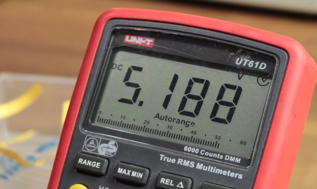
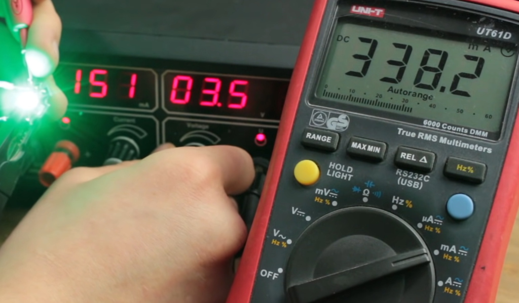
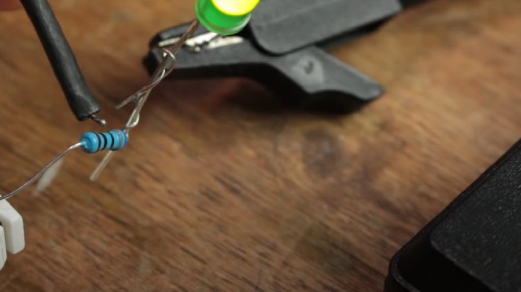
Before applying power to the circuit, always use a multimeter to verify the resistance of the resistor. A multimeter is a useful tool for measuring electrical values like voltage, current, and resistance. To measure resistance using a multimeter, you need to set it to the resistance mode and touch each lead of the resistor with the probes.
How To Wire Resistor Load in LED Lights:
Precautions
Before wiring a resistor load in LED lights, it is crucial to take certain precautions to ensure safety and optimal performance.
Here are a few precautions to consider:
- Check the LED Specifications: Verify the voltage and current requirements of the LED to determine if a load resistor is necessary;
- Heat Dissipation: Ensure that the load resistor is capable of handling the heat generated during operation. Choose resistors with appropriate power ratings to prevent overheating;
- Resistors in Parallel: When using multiple LEDs in parallel, each LED may require its own load resistor. Avoid using a single load resistor for the entire parallel circuit;
LED Resistor Wiring Diagrams
To help understand the wiring configurations for LED lights with load resistors, here are two common diagrams:
Series Circuit with Load Resistor:
LED Anode (+) —— Resistor —— LED Cathode (-)
In a series circuit, the load resistor is placed in series with the LED to limit the current flow.
Parallel Circuit with Load Resistor:
LED Anode (+) —— Resistor
|
|
LED Cathode (-) ——-|
In a parallel circuit, each LED may require its own load resistor to maintain proper current distribution.
Calculating the Size of a Load Resistor
To determine the appropriate size of a load resistor, you need to consider the forward voltage (Vf) and forward current (If) specifications of the LED. The general formula to calculate the resistance (R) is:
R = (Supply Voltage – Vf) / If
Explaining the Load
In LED lights, the load resistor is used to mimic the resistance of a traditional incandescent bulb. Incandescent bulbs have higher resistance, which limits the current flow. When replacing incandescent bulbs with LEDs, the reduced resistance can cause the LED to receive a higher current than it can handle, potentially leading to premature failure. The load resistor compensates for this difference by adding resistance to the circuit, effectively lowering the current.
Calculating the Size
To calculate the size of the load resistor, you need to determine the current flowing through the LED and the voltage drop across the resistor. The current can be obtained from the LED’s forward current specification, while the voltage drop is the difference between the supply voltage and the forward voltage of the LED.
Why the Wattage is Important
The wattage rating of a load resistor is essential to prevent overheating and ensure its longevity. The power dissipated by the resistor can be calculated using the formula [2]:
P = I^2 * R
where P is the power in watts, I is the current in amperes, and R is the resistance in ohms. Select a load resistor with a wattage rating higher than the calculated power to ensure it can handle the heat generated during operation. Failure to choose an appropriate wattage rating may result in the load resistor getting damaged or failing prematurely.
FAQ:
1. Which way do I wire a resistor?
Resistors are non-polarized components, meaning they can be connected in either direction. There is no specific positive or negative terminal for a resistor. You can connect the resistor in a circuit by simply attaching one lead to the desired starting point and the other lead to the desired ending point.
2. How should resistors be connected?
Resistors can be connected in various ways depending on the circuit requirements. The most common methods are series and parallel connections. In a series connection, resistors are connected end-to-end, with the total resistance being the sum of the individual resistances. In a parallel connection, the resistors are connected side by side, and the total resistance is calculated using the reciprocal formula.
3. Do you connect resistors to positive or negative?
Resistors can be connected to either the positive or negative side of a circuit, depending on the specific circuit requirements. The connection point will vary based on the overall circuit configuration and the specific role of the resistor in the circuit.
4. How to install a 120-Ohm resistor?
To install a 120-Ohm resistor, first, identify the specific location in the circuit where it needs to be connected [3]. Then, connect one lead of the resistor to the desired starting point and the other lead to the desired ending point in the circuit. Make sure the resistor is securely soldered or connected using appropriate wiring techniques.
5. Why is can having 120 Ohms at each end?
It seems that there may be an error or confusion in the question. Having 120 Ohms at each end does not convey a specific meaning or purpose. Resistors are used to control the flow of current and voltage in a circuit, and their specific resistance values are chosen based on the requirements of the circuit design.
6. Is there a 100-Ohm resistor?
Yes, there are 100-Ohm resistors available. Resistors are manufactured in a wide range of resistance values, including common values like 100 Ohms [4]. They are readily available in electronic component stores and online retailers.
7. Is a 10-Ohm resistor positive or negative?
As mentioned earlier, resistors are non-polarized components, so they don’t have a positive or negative terminal. A 10-Ohm resistor can be connected in either direction in a circuit.
8. What happens if the resistor is reversed?
If a resistor is reversed in a circuit, meaning its leads are connected in the opposite direction, it won’t function differently. The resistance value and the electrical characteristics of the resistor remain the same regardless of its orientation. However, reversing the resistor may affect the behavior of the circuit, depending on its specific role and the overall circuit configuration.
9. Do resistors fail open or closed?
Resistors generally fail in an open circuit condition, meaning they become non-conductive. In this state, the resistor no longer allows the flow of current, effectively disconnecting that part of the circuit. However, it’s important to note that different types of resistors may exhibit different failure modes, so it’s advisable to consult the datasheet or specifications provided by the manufacturer.
10. Can you reuse a resistor?
In most cases, resistors can be reused unless they have been damaged or their electrical properties have been compromised. If a resistor is in good condition, it can be removed from a circuit and used in a different circuit or application. However, care must be taken during the removal process to avoid damaging the resistor or its leads.
11. What happens if you connect an LED directly to a 12V DC?
If you connect an LED directly to a 12V DC power source without any current-limiting resistor, the LED may be subjected to excessive current and can be damaged or even destroyed. LEDs have specific voltage and current requirements, and without a current-limiting resistor, the LED will draw too much current, exceeding its maximum rating.
12. Does a resistor allow AC or DC?
Resistors allow both AC (Alternating Current) and DC (Direct Current). Resistors do not differentiate between AC and DC signals and provide resistance to the flow of current regardless of its type.
13. Do all resistors absorb power?
Resistors do absorb power in the form of heat dissipation. When current passes through a resistor, there is a voltage drop across it, and this voltage drop combined with the current flowing through the resistor results in power dissipation. The power dissipated by a resistor can be calculated using the formula P = I^2 * R, where P is power, I is current, and R is resistance [5].
14. Can a resistor have a negative voltage?
A resistor itself does not generate or exhibit voltage. However, when a resistor is placed in a circuit with a varying voltage source, it can experience a voltage drop across its terminals. This voltage drop can be positive or negative, depending on the polarity and characteristics of the voltage source and the circuit configuration.
15. Is there a 1-ohm resistor?
Yes, 1-Ohm resistors are commonly available. Resistors are manufactured in a wide range of resistance values, including very low values like 1 Ohm. They are widely used in various electronic applications where precise resistance values are required.
16. Why use a 50-Ohm termination?
A 50 Ohm termination is commonly used in applications involving impedance matching, especially in RF (Radio Frequency) systems. The 50-Ohm termination is often used in transmission lines, antennas, and other RF components to minimize signal reflections and ensure efficient power transfer. It helps in maximizing signal integrity and minimizing signal loss.
17. Does more ohms mean more current?
No, more ohms do not mean more current. In fact, according to Ohm’s Law (V = I * R), for a given voltage (V), an increase in resistance (R) will result in a decrease in current (I) [6]. The relationship between resistance and current is inversely proportional. Higher resistance values restrict the flow of current, whereas lower resistance values allow more current to pass through the circuit.
Useful Video: How to use a Resistor – Basic electronics engineering
References
- https://electrotopic.com/how-to-wire-a-resistor/
- https://sciencing.com/wire-resistor-load-led-lights-8596614.html
- https://www.instructables.com/How-to-Install-Load-Resistors-for-LED-Turn-Signal-/
- https://www.quora.com/How-do-you-wire-a-resistor
- https://do-it-up.com/vehicles/wiring/how-to-install-load-resistors-for-led-lights/
- https://itstillworks.com/measure-capacitance-cable-multimeter-8464791.html