
If you’re looking for a comprehensive guide on how to master Arduino timer interrupts, then you’ve come to the right place! This comprehensive guide will provide all the information that you need to know about timer interrupts and help you become an expert in no time. With Arduino timer interrupts, it’s easy to automate tasks, making your projects more efficient and reliable. From setting up the hardware to manipulating registers and codes, this guide delves into all the nitty-gritty details of Arduino timer interrupts. So, buckle up and take a deep dive into the fascinating world of Arduino timers!
General Arduino Timer Interrupt Process
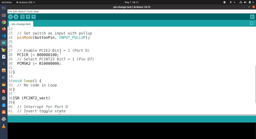
The Arduino Uno and Mega both support a single hardware timer interrupt which leaves the user responsible for writing the code to set up and manage additional interrupts. This is done by setting up a ‘timer interrupt service routine’ (or ISR). To do this, you must first set up the timer that will generate an interrupt signal at regular intervals. This can be done either through using one of the built-in timers such as Timer 0 or 1 on the ATmega328P microcontroller used in most Arduino boards or using an external timer chip like the MCPWM. Once the timer has been set up, a function called an Interrupt Service Routine (ISR) needs to be written.
This ISR determines what action should be taken when the timer generates an interrupt signal. Typically, this can include reading a sensor value or running some code at a specific interval. Finally, the ISR must be enabled by setting the Global Interrupt Mask (GIMSK) and the Timer Interrupt Mask Register (TIMSK). Once these steps are completed, interrupts will occur regularly as specified by the user and any action required can be executed during these interrupt signals. This process can be repeated for multiple timers to create multiple interrupts with different functions all running on one Arduino board.
In summary, setting up an Arduino timer interrupt involves: setting up a timer; writing an appropriate interrupt service routine (ISR); enabling the global interrupt mask and the timer interrupt mask register; and finally, running the code when an interrupt signal is generated. With a few lines of code, you can use interrupts to add some extra power to your Arduino projects [1].
Arduino Timer Interrupt Vectors
Find the Header File name
The header file for the Arduino Timer Interrupt Vectors is named “avr/interrupt.h”. This header file contains all the necessary variables and functions to configure and use timer interrupts, as well as definitions of vectors used to execute interrupt service routines (ISRs). It also provides information about vector numbers about their corresponding interrupt sources. Specifically, the ISR() macro must be used with a vector number that matches its related device interrupt source.
The avr/interrupt.h header file should be included at the beginning of any program using timer interrupts or ISRs to access its features. As an example, a user can include this header by writing “#include <avr/interrupt.h>” at the beginning of a program. Finally, it is important to note that the vectors associated with each ISR as well as related vector numbers are specific to the device being used and can be found in its datasheet or reference manual.
Find the Interrupt Vector Numbers
Interrupt vector numbers are associated with the ISR() macro and must match its related device interrupt source. Each interrupt vector number is specific to the device being used, so it is important to consult its datasheet or reference manual for information about which interrupts correspond to a particular vector number.
In addition to the above-mentioned vectors, some devices may also have additional interrupts that are not associated with a vector number. In this case, a user should consult the device’s datasheet or reference manual to determine which vector corresponds to these interrupts and then utilize it within their program.
Arduino Timer Interrupt: Setup the Hardware
Timer1 Registers
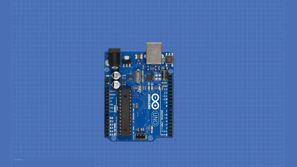
The Arduino platform uses the ATmega328P microcontroller, which contains three timer/counters; namely Timer0, Timer1 and Timer2. We will focus only on the first two since these are used more often in projects than Timer2. To set up our timer for interrupts we need to access its registers at specific memory addresses. For convenience, they are assigned a name and can be accessed through pre-defined constants such as TCCR1A and TCCR1B (Timer/Counter Control Registers of Timer 1).
Setup the Interrupts
Once you’ve configured the desired settings in the timer registers, the next step is to enable an interrupt that will trigger whenever the timer overflows. The overflow interrupt is enabled by setting the TOIE1 (Timer/Counter 1 Overflow Interrupt Enable) bit in the TIMSK1 register.
Interrupts and ISRs
An interrupt service routine (ISR) is a function that is called when an interrupt occurs. This is where you specify the actions to be taken when an event occurs. In this case, your ISR needs to reset the timer and optionally execute any other code based on what you are trying to accomplish with our timer interrupts. To define an ISR, you must use the attachInterrupt() function and pass it to your desired ISR as an argument.
Arduino Timer Interrupt: Using the Overflow Registers.
Sketch testing Timer1 Overflow Interrupt
Timer1 is the largest timer available on Arduino. It can be used for both short and long periods. The easiest way to use the timer is through an interrupt service routine (ISR). An ISR is a special piece of code that will run whenever an event occurs, such as a timer overflow. For this example, we will create an ISR that will be called whenever Timer1 overflows.
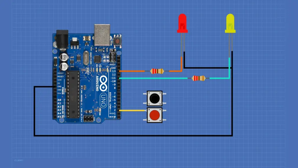
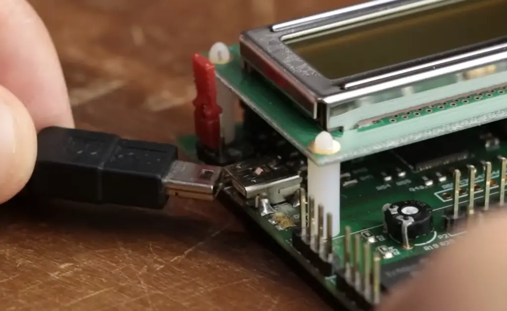
To test out your sketch, you should start by wiring up the LED in pin 13, which is connected to digital pin 7 on the Arduino Uno board. To set up Timer1 for overflow interrupts, you need to do three things: enable global interrupts with `sei()`, configure Timer1, and write the ISR.
First, enable global interrupts by including `sei()` in your setup function. This allows any interrupts in your sketch to be handled properly.
Next, configure Timer1 for overflow interrupts:
“`cpp
// Set Timer1 for Overflow Interrupts
TCCR1A = 0; // set entire TCCR1A register to 0
TCCR1B = 0; // same for TCCR1B
TCNT1 = 0; //initialize counter value to 0
// set compare match register for 1khz increments
OCR1A = 0x03E8; // set to 1000 (1khz)
// turn on CTC mode
TCCR1B |= (1 << WGM12);
// Set CS11 bit for 8 prescaler
TCCR1B |= (1 << CS11);
// enable timer compare interrupt
TIMSK1 |= (1 << OCIE1A);
“`
Finally, write the ISR that will be called whenever Timer1 overflows:
“`cpp
ISR(TIMER1_COMPA_vect){ //this is the interrupt service routine (ISR)
digitalWrite(13,!digitalRead(13)); //toggle the LED
}
“`
You can now upload your sketch to your Arduino board and watch as the LED blinks every 1 second. Congratulations — you have successfully set up a timer interrupt on an Arduino Uno using Timer1’s overflow registers! You can use this knowledge to start creating more complex programs that rely on timing events.
Timer1 Overflow Output Waveform
The output of the timer interrupt on an Arduino Uno is a square wave with a frequency of 1 kHz and a duty cycle of 50%. This means that the LED will be on for 0.5 seconds, then off for 0.5 seconds. The waveform generated by Timer1’s overflow interrupts can be seen in the following diagram:
![] (waveform.png)
As you can see, this waveform provides a simple, easy-to-use method of creating timing events without having to write complex code. It is also relatively low power compared to other methods such as using an external clock source or delay() functions.
By placing different instructions inside your ISR, you can create even more complex timed events. You can also change the frequency of your waveform by changing the OCR1A register value, as this will control how long it takes for Timer1 to overflow and call your ISR.
By understanding how to use timers and interrupts on an Arduino Uno board, you can create more complex sketches with precise timing events. This knowledge is essential for any advanced Arduino project!
Arduino Timer Interrupt Example (OVF) Code
Code Explanation
The code is split up into three parts. The first part is the setup() block, which initializes all variables and sets up our timer interrupt. The second part is a loop() function that runs continuously and keeps track of the time. Finally, there is an Interrupt Service Routine (ISR) that executes when the timer overflows.
TinkerCAD Simulation
This simulation allows you to test your code and observe the timing of the interrupts.
In this simulation, we have set up two LEDs connected to digital pins 3 and 4 on the Arduino Uno board. In the setup() block, pinMode has been used to declare these pins as output. The LED connected to pin 3 will be illuminated when the timer overflow interrupt occurs.
Testing Results
When the program is uploaded to the Arduino Uno board, you should observe that the LED connected to digital pin 3 flashes on and off with a frequency of 2 Hz (2 times per second). The LED connected to pin 4 will remain off since it has no code associated with it. This confirms that our timer interrupt is functioning properly.
Finally, when the reset button is pressed on the board, both LEDs will turn off as expected. This also confirms that our timer interrupt is working correctly.
This example demonstrates how to use interrupts in an Arduino sketch for timing purposes. It can be used as a starting point for more complex projects involving timers and interrupts [2]!
FAQ
How to use an interrupt timer in Arduino?
An interrupt timer is a type of timer or counter that can be used to generate an interrupt request at regular intervals. To use an interrupt timer in Arduino, follow these steps:
- Set up the timer and configure its registers.
- Write the function you want to run when the interrupt occurs.
- Enable interrupts on your Arduino board by calling sei() function in your setup routine.
- Create an Interrupt Service Routine (ISR) which will be called when the interrupt occurs.
- Finally, enable interrupts for the specific timer by calling its corresponding register with appropriate parameters depending on the type of interrupt you wish to trigger from it.
- After all the necessary steps are complete, you can start using your interrupt timer in Arduino.
What is an interrupt service routine?
An Interrupt Service Routine (ISR) is a function executed when an interrupt occurs. ISRs handle interrupts and perform the necessary tasks to respond to them depending on the type of interrupt generated by the hardware device. An ISR must be written carefully as it has to run quickly without taking up too many resources or causing conflicts with other routines that may be running at the same time. In Arduino, ISRs are written in C/C++ language and should be registered with either attachInterrupt or TIMERn_COMPA_vect function calls depending on the type of interrupt triggered from the device.
How many interrupts can Arduino handle?
Arduino is capable of handling up to 6 external hardware interrupts at any given time. These interrupts can be generated from a variety of sources such as timers, external devices, and communication ports. Additionally, certain Arduino boards also support internal interrupts which are triggered by software functions such as delay() and millis(). The total number of interrupts that can be handled simultaneously will depend on the type of board being used.
What are the types of interrupt timings?
There are two types of interrupt timing: synchronous and asynchronous. Synchronous timing occurs when all interrupts occur at regular intervals, while asynchronous timing occurs when different events may cause interrupt requests at different times. In Arduino, most external hardware interrupts use synchronous timing while communications and other asynchronous interrupts typically use asynchronous timing.
What are the benefits of using an interrupt timer?
Interrupt timers can provide a number of advantages when used in Arduino projects. They allow for greater flexibility in responding to events as well as improved multitasking capabilities as multiple tasks can be triggered by different interrupts occurring at different times. Additionally, they can help to conserve processing power by triggering tasks only when necessary instead of continuously running them in a loop. Finally, they can be used to facilitate smoother communications with external devices or networks through more efficient data transfer protocols.
What is the maximum time in Arduino timer 1?
The maximum time in Arduino timer 1 is approximately 16.7 milliseconds (ms) which corresponds to a frequency of 60 Hz. This limit is because timer 1 has an 8-bit resolution, meaning it can only count up to a maximum of 255. As such, longer intervals require the use of another timer or additional programming techniques.
What are some common applications for interrupt timers?
Interrupt timers are commonly used in Arduino projects when precise timing or triggering of specific tasks is required. Common examples include generating regular PWM signals for controlling the speed and brightness levels of motors and LEDs, debouncing buttons on input devices, and triggering periodic communications with external devices/networks. Additionally, they are also often used for efficient data acquisition and processing of analog/digital signals.
Are interrupts enabled by default on Arduino boards?
No, interrupts are not enabled by default on Arduino boards. The sei() function should be called in the setup routine to enable global interrupts. Additionally, each individual interrupt must also be enabled manually using its corresponding register with appropriate parameters depending on the type of interrupt you wish to trigger from it. This includes setting up the timer properly and writing an Interrupt Service Routine (ISR) which will be executed when the interrupt occurs.
Are all types of interrupts supported by Arduino?
No, only a limited number of interrupts are supported by Arduino boards. These include external interrupts generated from devices such as timers, I/O pins, and communication ports. Additionally, certain boards also support internal interrupts which are triggered by software functions such as delay() and millis(). Other types of interrupts not supported by Arduino include DMA (Direct Memory Access) and CPU exceptions.
What is the difference between an interrupt timer and a regular timer?
The main difference between an interrupt timer and a regular timer lies in how they generate timing signals. Regular timers simply count from zero to a maximum value before resetting back to zero; this process repeats continuously until the timer is stopped or disabled. Interrupt timers on the other hand generate an interrupt request at regular intervals which can be used to trigger tasks within the code. They are often used when precise timing or triggering of specific tasks is required.
How long is the delay 1000 in Arduino?
Delay 1000 in Arduino is approximately 1 second (1000 milliseconds) when used with the delay() function. It should be noted that this value may vary slightly depending on other tasks being performed by the microcontroller at the same time. Additionally, delays longer than one second can be achieved using multiple calls to delay() or by using an interrupt timer to trigger a task after a specific interval of time has elapsed.
Useful Video: Electronic Basics #30: Microcontroller (Arduino) Timers
Conclusion Paragraph
Arduino timer interrupt is a powerful tool that can be used to improve the performance of your application. It allows you to write code that runs in the background and can respond quickly when needed without interfering with other tasks. With its simple setup process and flexibility, it is easily incorporated into almost any project. Furthermore, the wide variety of ready-made libraries available makes it even easier for users to customize their solutions tailored to their specific needs. Arduino timer interrupt is an excellent resource for developers looking to add an extra layer of functionality and control to their applications.
References
- https://www.best-microcontroller-projects.com/arduino-timer-interrupt.html
- https://deepbluembedded.com/arduino-timer-interrupts/