
The Hitachi HD44780 LCD Controller is a powerful and versatile tool for anyone who wants to make amazing projects with Arduino. With its simple step-by-step instructional guide, you’ll be able to quickly learn how to use HD44780 and unlock the full potential of Arduino. Whether you’re a hobbyist or an experienced engineer, this guide will provide you with the knowledge and tools necessary to create incredible projects that will amaze your friends and family!
What is Hitachi HD44780?
The Hitachi HD44780 is an LCD controller that was originally designed to control simple text-based displays. It has been widely used in a variety of display applications, ranging from calculators and car stereos to medical equipment and consumer electronics. The HD44780 is capable of displaying up to 8 lines of characters on a single screen, with each character having a resolution of 5 x 8 pixels.
The controller also supports control functions such as cursor movement, scrolling, and the ability to switch between two sets of fonts. In addition, the device also supports communication protocols such as I2C and SPI for connecting it to external components. With its versatile design and wide range of features, the HD44780 remains one of the most popular LCD controllers in use today.
The HD44780 is an easy-to-program controller, allowing developers to quickly and easily create displays with a variety of features. For its time, the HD44780 offered advanced features such as high-contrast display modes, adjustable character size, and extended character sets. Even today, many manufacturers offer low-cost LCDs based on the HD44780 controller.
Liquid Crystal Displays (LCD) with Arduino
Hardware Required
- LCD (Liquid crystal display)
- Arduino board
- Potentiometer
- Breadboard and its wires
How it works?
The basic idea behind an LCD is to reflect light in order to produce images. An LCD consists of two sheets of polarizing material with a liquid crystal solution between them. When a voltage is applied across the liquid crystals, they align so that light cannot pass through them. This creates dark areas on the screen where no image can be seen. By controlling the electric current flowing across each individual pixel, different levels of illumination can be achieved, allowing for the formation of various types of images.
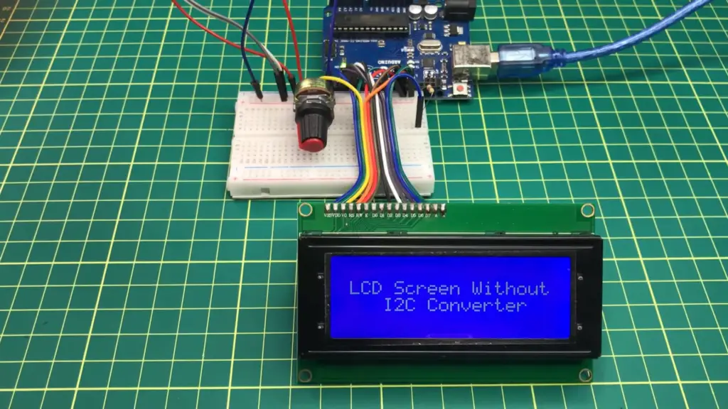
In this project you will use an Arduino board to control an LCD. The Arduino will be used to control the voltage applied to the LCD and thus dictate what images are displayed. A potentiometer will be used to adjust the brightness of the display.
Assembly
First, connect the LCD module to a breadboard with its wires:
- Connect one end of the data cable (usually yellow) to digital pin 2 on your Arduino board
- Connect one end of the power cable (usually red) to 5V on your Arduino board
- Connect one end of the ground cable (usually black) to GND on your Arduino board
- Next, connect a 10K potentiometer across pins 3 and 4 of your LCD module. This will allow you to adjust the contrast of the display.
Finally, connect the other end of each cable to its respective pin on the LCD module (data to pin 2, power to pin 3 and ground to pin 4).
Programming
Now it’s time to upload your code. You can use the Arduino IDE or a text editor like Atom or Sublime Text if you’re comfortable with programming in C/C++. The following code will allow you to control the LCD display using your Arduino board:
“`c++
// Include necessary libraries
#include // Define pins used for connections
const int rs = 2; const int en = 3; const int d4 = 4; const int d5 = 5; const int d6 = 6; const int d7 = 7; // Create LiquidCrystal object
LiquidCrystal lcd(rs, en, d4, d5, d6, d7); void setup() { // Initialize LCD with 16 columns and 2 rows lcd.begin(16, 2); } void loop() { // Display a custom message on the LCD screen lcd.setCursor(0, 0);
lcd.print(“Hello World!”); }
“`
Save your code to your computer and upload it to the Arduino board using the USB cable. Once the code is uploaded, you should be able to see “Hello World!” on the LCD screen.
You can now adjust the contrast of the LCD by turning the potentiometer. You can also make modifications to your code in order to display custom messages on the LCD [2].
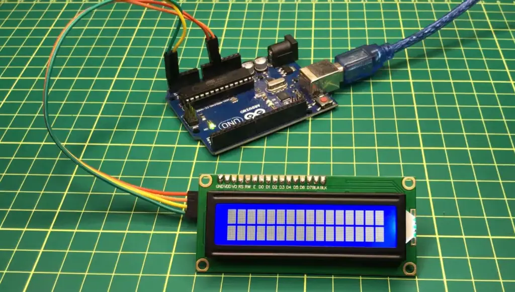
Parallel Interface: Getting Started with a JHD162A 16×2 display
JHD162A Pins
The JHD162A display consists of 16 pins: 8 data pins, 2 control pins and 6 power supply pins. The data pins are used to transfer the data from the microcontroller to the LCD module. The control pins consist of RS (Register Select) and EN (Enable). These two control signals are used to determine whether the signal on the data bus is a command or data. They also enable writing to the LCD module. Finally, there are 6 power supply pins that provide power for operating/driving the LCD module.
4 bit and 8 Bit Modes
The JHD162A display can operate in either 4-bit or 8-bit mode. In 4-bit mode, only the lower four data lines (D4-D7) are used; the upper four data lines (D0-D3) remain unused. As a result, it takes two 8-bit transfers to send 1 byte of data in 4-bit mode.
In 8-bit mode, all eight data pins (D0-D7) are used and it takes just one transfer to send 1 byte of data. This makes 8-bit mode faster than 4-bit mode but requires more pins on the microcontroller side.
Interfacing with a Microcontroller
Interfacing a JHD162A 16×2 display to a microcontroller requires four basic steps:
- Setting up the LCD module. This involves initializing the LCD with necessary commands (such as set cursor position, set display mode, etc.) before any data can be written to it.
- Writing data/commands on the data pins of the LCD module. Depending on whether 4-bit or 8-bit mode is being used, this process will involve either two transfers (in 4-bit mode) or one transfer (in 8-bit mode).
- Sending control signals to tell the LCD what type of data is being sent: command or data. This is done using the RS and EN control pins.
- Making sure all power supply pins are connected correctly to the microcontroller.
These four steps are necessary for any kind of data transfer between a microcontroller and an LCD module, regardless of type or model. Once these steps have been completed, you can start writing text or images to the display!
Sketch and Demo
The code for interfacing a JHD162A 16×2 display with an Arduino microcontroller can be found in the following link: This code will demonstrate how to write text and images to the display using 4-bit or 8-bit mode. It also includes a simple demo sketch that you can use to test your setup [3].
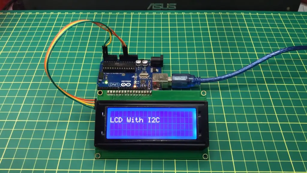
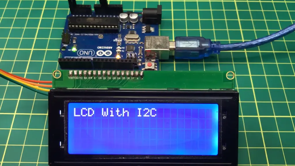
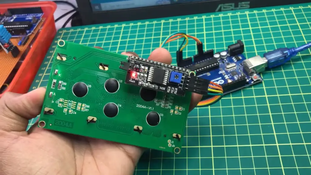
I2C Interface: Getting Started with a 20×4 display with I2C daughter board
Circuit diagram
To connect the display with an I2C daughterboard, you need to create a circuit diagram.
- Raspberry Pi SDA pin (GPIO2) -> I2C daughter board SDA pin
- Raspberry Pi SCL pin (GPIO3) -> I2C daughter board SCL pin
- Display VCC -> 5v power supply
- Display GND -> Ground
- Display SDA and SCL pins -> I2C daughter board SDA and SCL respectively
Software Setup for the Display with I2C daughter board
Before you can get started with setting up the display, you need to make sure that the Raspberry Pi is connected to the internet. Once your raspberry pi is connected to the internet, follow these steps:
- Open a terminal window and type in `sudo raspi-config`
- Select Interface Options -> I2C -> Yes
- Click Ok and then reboot your Raspberry Pi
- After rebooting your Raspberry Pi, open a new terminal window and type in `sudo apt-get update && sudo apt-get install -y python-smbus i2c-tools` (if it’s already installed, then skip this step)
- Now, type in `sudo i2cdetect -y 1` and you should see a new address at 0x27 this is the address of the I2C daughter board).
- Finally, type in `sudo nano /boot/config.txt` and add the following lines:
- dtparam=i2c_arm=on
- dtoverlay=pcf8574,addr=0x27
- Save the file by pressing ctrl+X then Y and press Enter.
You can now test if your display is working correctly by connecting it to your raspberry pi using an I2C daughterboard. You can use this guide to help step).
Backlight Control
You can control the backlight of the display by using a potentiometer. To do this, simply connect one end of the potentiometer to 5 volts and the other end to the ground. Then, connect the middle of the potentiometer to pin 7 on your Idaughterboardard. This will allow you to adjust the brightness of your display’s backlight.
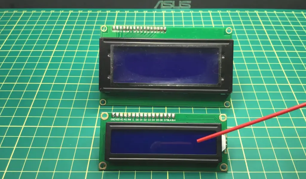
20×4 LCD memory map and line overflow
The 20×4 LCD display has a total of 80 characters split across four lines. Each line can contain up to 20 characters but if you try to print more than 20 characters on one line, it will overflow onto the next line. This means that the first 40 characters you type will be displayed on the first two lines and the remaining 40 characters will be displayed on the third and fourth lines. You can also use special commands in your code to control which part of your text will appear on each line.
Overall, setting up and programming a 20×4 LCD display with an I2C daughter board is relatively simple. With just a few steps, you can get your Raspberry Pi connected to the display and enjoy displaying text and data in whatever format you like.
FAQ
How to connect 16 * 2 LCD to Arduino?
To connect your 16 * 2 LCD to Arduino, use the following steps:
- Connect the LCD’s GND pin to a Ground Pin on the Arduino board.
- Connect the LCD’s VCC pin to the 5V pin on the Arduino board.
- Connect the LCD’s RS (register select) pin to digital pin 12 on the Arduino board.
- Connect the RW (read/write) pin of LCD to GND of Arduino board.
- Connect E (enable) pin of LCD to digital pin 11 on arduino board.
- Connect D4-D7 pins on LCD with digital pins 5-8 respectively on arduino board .
- Connect A (backlight) pin to 5V of arduino board.8. Finally, upload the LCD test code from the Arduino IDE to check if your connections are correct and it is working properly. That’s all you need to do in order to connect your 16 * 2 LCD with Arduino!
What voltage does an LED require?
Most LEDs require a forward voltage of 1.8 – 3.3 volts, depending on the color of the LED and its brightness level. To determine what voltage your particular LED requires, refer to its datasheet or contact the manufacturer for more information. Additionally, be sure not to exceed 20mA as this can damage or destroy your LED. Always use a current-limiting resistor when connecting an LED to a circuit.
What is the difference between Arduino Uno and Nano?
The main differences between Arduino Uno and Nano are their size, power consumption, I/O pins, clock speed, analog input pins, USB interface type, and cost. Arduino Uno is larger than the Nano due to its extra components; it has more I/O pins (14 digital compared to 8 on the Nano), more analog input pins (6 compared to 2 on the Nano), operates at 16 MHz clock speed compared to 8MHz for the Nano, runs on 5V while the Nano runs on 3.3V; it also requires an FTDI programmer for programming whereas the nano has a built-in USB-to-serial converter. The Uno is also more expensive than the Nano, so it all depends on your project requirements and which board to use.
Are there any safety precautions when using Arduino?
Yes, there are several safety precautions you should take when working with Arduino boards:
- Make sure to power off your board before connecting or disconnecting any peripherals such as motors, sensors, and other components.
- Wear an anti-static wrist strap when handling the circuit boards or electronic components to avoid static electricity that can damage sensitive parts of the board.
- Never connect two power sources simultaneously, as this could cause a short circuit that may damage your board or cause a fire.
- Always double-check your connections and code before powering on the board as incorrect wiring or coding can damage components connected to the board.
- Ensure that all components used are compatible with Arduino boards, such as sensors, motors, and other peripherals. If you have any doubts about the compatibility of a component, contact the manufacturer for more information.
- For indoor projects, always use electrical enclosures to protect children from exposed circuitry.
- Be sure to unplug USB cables when not in use to avoid accidentally powering on your board or draining its battery life unnecessarily.
- Finally, always make sure to follow safety guidelines when working around electricity – never work near water or with wet hands, and never touch any exposed wires. These are some of the safety precautions you should take when using Arduino boards. Follow them and you’ll be sure to have a safe and successful experience working with Arduino!
What is the operating voltage for an Arduino board?
The operating voltage for an Arduino board is usually 5V or 3.3V depending on the type of board. The Uno, Mega 2560, and Due all operate at 5 volts while the Nano operates at 3.3 volts. Always refer to your particular board’s datasheet for more information about its power requirements before connecting components or peripherals to it. Additionally, use a regulated power supply when powering your board as voltage fluctuations can damage sensitive components.
How to check 16×2 LCD display with Arduino Uno?
To check 16×2 LCD display with Arduino Uno, follow these steps:
- Connect your LCD to the Arduino board according to the pin connections specified above in the FAQ section.
- Upload any sample code from the Arduino IDE or write your own code to test LCD output.
- If you’re using a sample code, make sure that all pins are correctly defined; some sample codes might require changing pin numbers based on where you connected them.
- After uploading the code, open Serial Monitor and set the baud rate and line ending as required by the program for testing purposes.
- You should now be able to see text being printed on your screen if everything is set up correctly.
- If you don’t see any text, check all the connections and verify that your code is sending output to the serial monitor.
- Once you have successfully tested the LCD display with Arduino Uno, you can start developing projects with it!
Why do you use a resistor with an LED?
You use a resistor with an LED to prevent it from drawing too much current and damaging itself or the circuit. LEDs require a precise amount of current to operate correctly; too little and they won’t light up, and too much will cause them to burn out quickly. Using a resistor limits the current passing through the LED, thus protecting it from damage. The value of the resistor used depends on multiple factors such as the operating voltage, forward voltage drop of the particular LED, and its desired brightness level. Therefore, always refer to your LED’s datasheet for more information about selecting an appropriate resistor. This is why we use resistors when working with LEDs!
Is it necessary to use a breadboard with Arduino?
No, it is not necessary to use a breadboard with Arduino. However, it can be helpful when prototyping or testing ideas as it allows you to quickly and easily connect components without having to solder them. Additionally, using a breadboard makes your project much more portable and flexible; you can easily disconnect the components from the board and move them onto a permanent circuit at any time. Therefore, if you’re planning on doing a lot of prototyping or experimentation with Arduino boards, then investing in a breadboard would be beneficial!
What is the purpose of an LCD display?
An LCD (Liquid Crystal Display) display is a type of display usually used for displaying text, images, or animated graphics. LCDs are composed of two sheets of polarized material with a liquid crystal solution between them. When an electrical charge is applied to the liquid crystal, it twists and aligns the molecules in a manner which allows light to pass through and form an image on the display. LCDs can be used for a variety of applications such as displaying data from sensors or any other type of information. They’re also commonly used in TV screens, computer monitors, and even some mobile phone displays! Therefore, LCDs are essential components to consider when creating projects with Arduino boards.
Useful Video: How to Use I2C LCD with Arduino | Very Easy Arduino LCD I2C Tutorial | Arduino 16×2 LCD I2C Tutorial
Conclusion Paragraph
Using Hitachi HD44780 with Arduino is a simple and cost-effective way to get your projects up and running. The Hitachi HD44780 LCD can be used to display text, numbers, or custom symbols. It is an easy-to-use device with plenty of features that make it suitable for a variety of applications. With an Arduino board, the Hitachi HD44780 LCD can be connected quickly and easily, allowing you to create a wide range of projects. Whether you need to display simple messages or complex graphics, the HD44780 will help bring your project ideas to life! The versatility of the Hitachi HD44780 makes it an ideal choice for those looking for a reliable and affordable solution for their project needs.
References
- https://www.wikiwand.com/en/Hitachi_HD44780_LCD_controller
- https://docs.arduino.cc/learn/electronics/lcd-displays
- https://www.circuitschools.com/interfacing-lcd-display-with-arduino-in-detail/