With the help of an INA219, you can add powerful measurement capabilities to your Arduino project! Designed for efficient and accurate current, voltage, and power measurements with minimal external components, the INA219 is a perfect way to expand your project’s capabilities. The INA219 is great for DIY projects such as monitoring solar energy harvesting or measuring load current and power used by devices. This post will explore how easy it is to get started using the INA219 with Arduino.
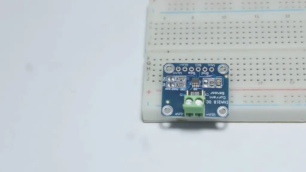
INA219 Current Sensor Module Components
Current Sensing Resistor
The current sensing resistor is a key component of the INA219 current sensor module. This resistor is placed in series with the output side of the circuit, and its value determines the amount of current that can flow through it (in amperes). The larger the value of this resistor, the lower the maximum current that can be sensed by the module.
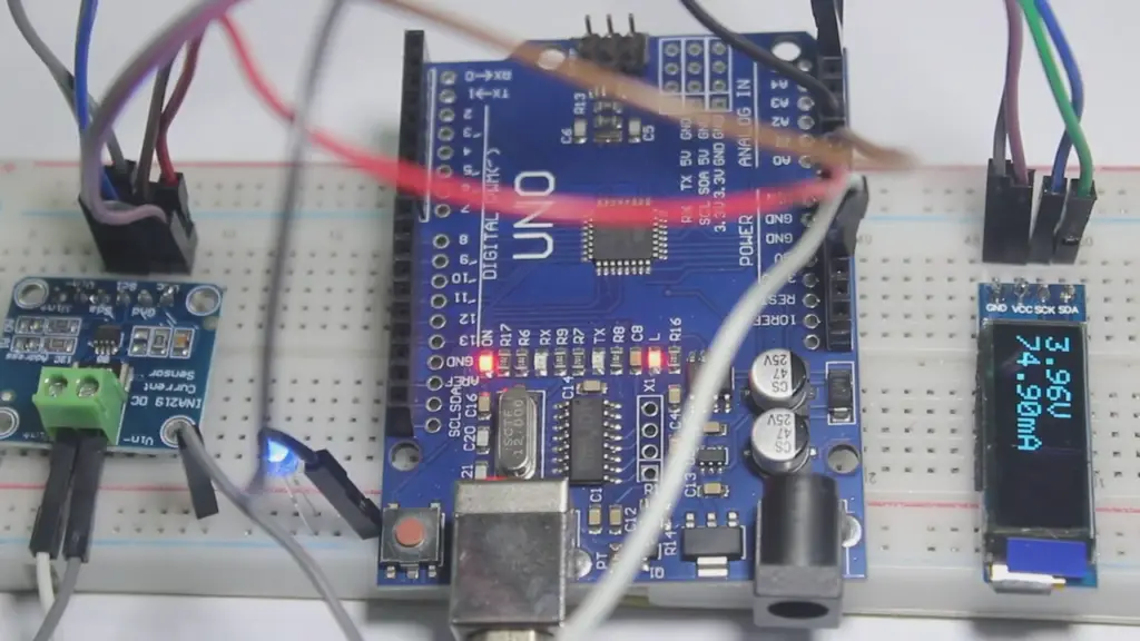
Voltage Divider Circuit
The voltage divider circuit on an INA219 module takes an input voltage from a power source, divides it down to a lower level, and then outputs it to two pins on the board. By doing so, it allows for precise measurements of both voltage and current levels without having to use additional external components or devices.
INA219 Chip
The INA219 chip is the heart of the module. It contains all the necessary circuitry to measure both voltage and current levels, as well as any necessary additional features such as overvoltage and under-voltage protection. The chip also includes a built-in temperature sensor which can be used to monitor the internal conditions of the module for safety purposes.
I2C Interface
The I2C interface is used to communicate with and control the INA219 current sensor module. By using this interface, it is possible to read or write data from/to the INA219 to set parameters such as gain, offset, polarity, etc., or even read measured values such as bus voltage, shunt voltage, and current levels.
Power Indicator LED
The power indicator LED is used to indicate whether the INA219 module is powered on or off. When it is lit up, it means that the module is powered on and ready to take measurements. It also has the added benefit of being able to detect shorts in circuit connections as well as other potential issues with an electric circuit.
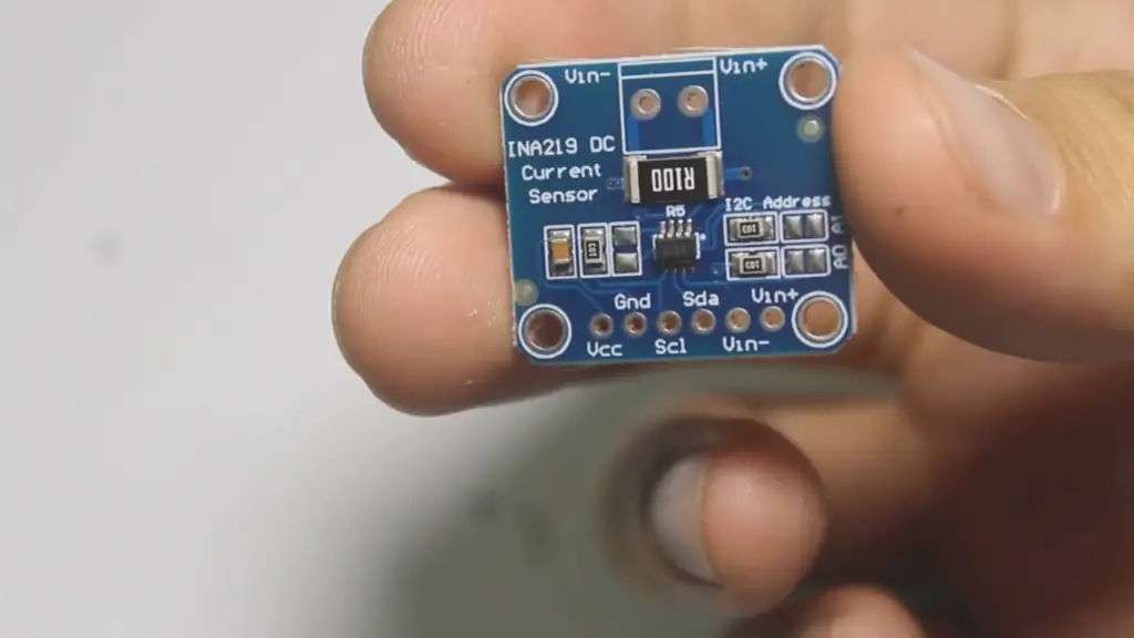
INA219 Pinout
The INA219 module has 8 pins, of which 6 are used for power and communication. The other two pins are used to connect the current sensing resistor to the circuit being measured. Below is a list of the pinout diagram for the module:
- VCC – Power supply voltage (5V)
- GND – Ground connection
- SCL – Serial Clock Line (I2C)
- SDA – Serial Data Line (I2C)
- VS+ – Positive output of voltage divider
- VS- – Negative output of voltage divider
- CS+ – Connection point for current sensing resistor
- CS- – Connection point for current sensing resistor.
Specifications of the INA219 Current Sensor:
Supply voltage:
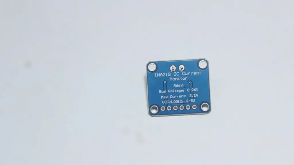
The operating voltage of the INA219 current sensor ranges from 3.3V to 5.5V, with an operating temperature range of -40°C to +125°C.
Current sensing:
This device can measure both AC and DC currents by using a shunt resistor in series on the ground wire or bus. The maximum continuous current that can be read is 2A, while the maximum peak current is dependent on the power supply voltage.
Output formats:
The INA219 features two different output formats: analog and digital. The analog format provides a simple linear output signal which can be easily converted to either AC or DC current readings with an appropriate amplifier circuit, while the digital format provides a more accurate measurement with up to 12-bit resolution.
Shunt voltage and Bus voltage:
The device can measure both the shunt voltage and bus voltage, with a maximum input range of 0-36V for each. The resolution is adjustable from 10µV to 40mV depending on the level of accuracy required.
ADC Resolution and Accuracy:
The INA219 features an onboard 12-bit Analog-to-Digital Converter (ADC) which can be configured for either single-ended or differential mode. The onboard ADC has a maximum resolution of 0.025%, with a typical error rate of less than 0.1%.
Power Consumption:
The average power consumption of the device is 1mW when in standby, rising to 20mW during active operation. This makes the device extremely efficient, allowing it to operate from small batteries or other low-power sources.
Connectivity:
The INA219 supports both I2C and SPI communication protocols, enabling easy integration into existing systems. Additionally, the device can be controlled directly from a microcontroller or an embedded processor using one of the available libraries.
Applications:
The INA219 current sensor is suitable for applications such as battery management, motor control, solar power monitoring, and industrial automation. It can also be used in electric vehicles and other transportation systems to monitor currents up to 2A. Additionally, the device is commonly used in consumer electronics such as laptops, smartphones, tablets, wearables, and IoT devices.
Interfacing the INA219 with the Arduino
Components Required
- – INA219 Breakout Board
- – Arduino Uno or equivalent microcontroller board
- – Jumper cables
INA219 connection with Arduino
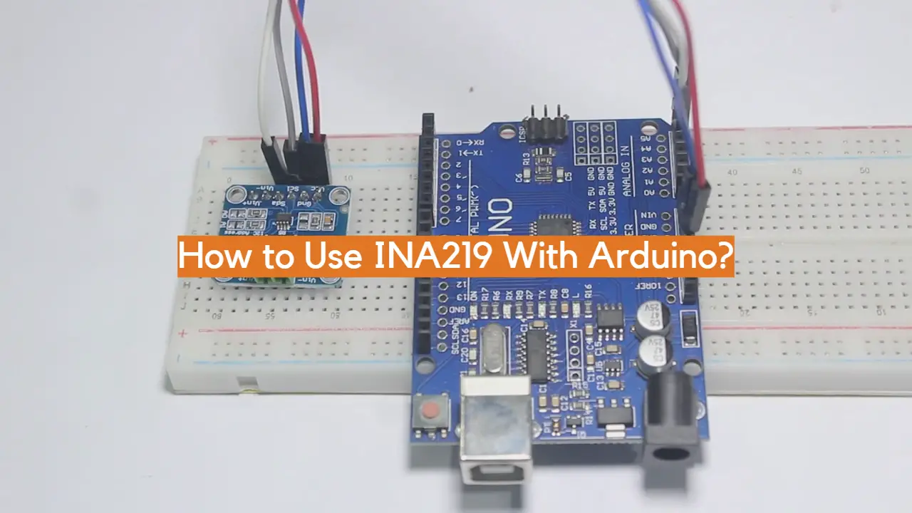
The INA219 breakout board has four pins namely, Vcc which is connected to the 5V on the Arduino board, GND to ground or 0V of the Arduino board, and SDA and SCL pins are for I2C communication with the Arduino.
- Start by connecting the INA219’s Vcc pin to the 5V power pin on your arduino.
- Then connect its ground (Gnd) pin to one of the Gnd pins on your arduino.
- Next, connect its SDA pin to A4 and its SCL pin to A5 on your arduino board respectively.
- Power up your microcontroller, either using a power supply or your computer via USB cable.
- That’s it! Your INA219 is now connected to the Arduino board and ready for use.
Now that you have successfully connected the INA219 breakout board with an Arduino, it’s time to write some code and get your project running. The following section will show you how to write a basic sketch using the I2C library of Arduino IDE which can be used to read data from the INA219.
Reading Data from the INA219 using Arduino
The first step in reading data from the INA219 is to ensure that the I2C communication between the microcontroller and the sensor is set up correctly. To do this, you need to include the Wire library and then begin I2C communication by calling the “Wire.begin()” command in your code.
Once the I2C connection has been established, you can call any of the functions that are provided by the INA219 library to read data from the chip. For example, if you want to read the current value of voltage at its input terminals, you can use the getBusVoltage_V() function. Similarly, if you need to read current values from your circuit, simply use the getCurrent_mA() function.
After reading all required data from the INA219 sensor using Arduino IDE programming language, you can display it on an LCD or OLED display or log it onto a computer or cloud server.
This is how you can use an INA219 current sensor with Arduino to measure and monitor the current in your circuit. If you have any queries regarding this tutorial, feel free to comment below.
Demonstration of the INA219 with the Arduino:
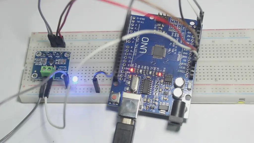
To demonstrate the working of the INA219 current sensor, you should use an Arduino Uno board and a 10-ohm resistor. You will connect one end of the resistor to the 5V output pin on the Arduino board and the other end to its A0 pin which is used as an analog input (in this case, for sensing current).
You will then connect the INA219 sensor to the Arduino board using four jumper cables as mentioned earlier. In this setup, you will use Arduino’s A4 and A5 pins for I2C communication with the device. After powering up your microcontroller, upload a simple code to your board that reads data from the INA219 and displays it on an OLED display or LCD screen.
INA219 current sensor Arduino Code
Now that you have the INA219 wired up properly, get started with writing some Arduino code. Here’s a basic sketch that will read and log the current draw on an I2C bus:
“`
// Include libraries
// i2c library to communicate with ina219 over I2C bus
#include “Wire.h”
// INA219 library to work with the sensor
#include “INA219.h”
// Create an instance of the INA219 class
INA219 ina219;
void setup() {
Serial.begin(115200);
// Initialize the INA219 device using default settings
ina219.begin();
}
void loop() {
// Read the current draw from the sensor
float current_mA = ina219.getCurrent_mA();
Serial.print(“Current Draw: “);
Serial.println(current_mA);
delay(1000);
} “`
That’s all the code you need to get started with reading and logging the current draw from an I2C bus using the INA219 current sensor. Now, if you want to log this data over time or combine it with other sensors, you can easily modify this code to do that as well! Have fun building projects with your new INA219 current sensor!
FAQ
How to connect INA219 to Arduino?
Connecting the INA219 to an Arduino is a fairly simple process that requires just a few steps. First, you’ll need to connect your INA219 module to the 5V and GND pins on your Arduino board, making sure that the VCC pin is connected to the 5V pin. Next, connect the SDA and SCL pins from the INA219 module to A4 (SDA) and A5 (SCL) of your Arduino board using male-to-female hookup wires. Finally, plug in your power supply unit into an outlet and connect it with your Arduino board before powering up both devices. You should now be able to read current measurements from your INA219 module!
How to use a voltage sensor with Arduino?
Connecting a voltage sensor to an Arduino board is quite simple. First, you’ll need to connect the 5V and GND pins of your voltage sensor with the corresponding pins on your Arduino board. Then, you will need to connect the SDA and SCL pins from the voltage sensor to A4 (SDA) and A5 (SCL) of your Arduino board using male-to-female hookup wires. Finally, plug in your power supply unit into an outlet and connect it with your Arduino board before powering up both devices. At this point, you should be able to start measuring voltages from your voltage sensor!
Are current sensors and current meters the same?
No, current sensors and current meters are not the same. A current sensor measures an electrical current by producing a voltage that is proportional to the current, while a current meter is used to measure and display the amount of electricity flowing through a particular circuit. To put it simply, a current sensor can be used to monitor and detect changes in the flow of electricity, while a current meter can be used to measure how much electricity is being consumed.
What is the purpose of INA219?
The INA219 is an integrated circuit designed for monitoring both DC and AC currents in automotive applications. It consists of two main components – a 16-bit ADC (Analog-to-Digital Converter) and a programmable gain amplifier (PGA). The PGA is used to amplify the differential voltage between two wires, while the ADC converts this differential voltage into a digital signal. This digital signal can then be used by an Arduino or other microcontroller to measure currents over time and detect any errors in the current readings.
How do I program an Arduino?
Programming an Arduino board requires knowledge of C/C++ programming language and basic electronics principles. You should first familiarize yourself with the basics of the Arduino platform before attempting to write any code for it. Once you have a basic understanding of how an Arduino works, you can begin writing your own sketches (programs) using either the Arduino IDE or other development platforms such as Atmel Studio, AVR Studio, etc. After coding your sketch, you can upload it to your Arduino board using the USB cable provided with the board and test out your program.
What is an analog sensor?
Analog sensors are devices that measure physical quantities (such as light, temperature, etc.) by converting them into a continuous voltage or current signal. These signals can then be read and interpreted by microcontrollers such as Arduinos to calculate various parameters related to those physical quantities. Analog sensors are commonly used in robotics applications where they provide feedback on different environmental parameters like light intensity, temperature, humidity, etc. They are also used in various industries for process automation and control purposes.
How does the INA219 work?
The INA219 is an integrated circuit designed for monitoring both DC and AC currents in automotive applications. It consists of two main components – a 16-bit ADC (Analog-to-Digital Converter) and a programmable gain amplifier (PGA). The PGA is used to amplify the differential voltage between two wires, while the ADC converts this differential voltage into a digital signal. This digital signal can then be used by an Arduino or other microcontroller to measure currents over time and detect any errors in the current readings.
How to use a non-invasive current sensor Arduino?
Using a non-invasive current sensor with an Arduino is quite simple. First, you’ll need to connect the 5V and GND pins of your non-invasive current sensor to the corresponding pins on your Arduino board. Then, you will need to connect the SDA and SCL pins from the non-invasive current sensor to A4 (SDA) and A5 (SCL) of your Arduino board using male-to-female hookup wires. Finally, plug in your power supply unit into an outlet and connect it with your Arduino board before powering up both devices. At this point, you should be able to start measuring currents from your non-invasive current sensor!
Can I use multiple current sensors on one Arduino board?
Yes, you can use multiple current sensors on one Arduino board. However, it is important to note that each current sensor will need to be connected to its own independent I2C bus (SDA and SCL pins) in order for the Arduino board to be able to detect each individual sensor’s readings. Additionally, if you are using more than one current sensor on a single Arduino board, you may need an external power source due to the total power consumption of all the connected current sensors.
What can I use a voltage sensor with an Arduino for?
Using a voltage sensor with an Arduino allows you to measure and monitor changes in voltages over time. This information can then be used to control or adjust various aspects of a project, such as the speed of motors or fans, the brightness of LEDs, etc. It can also be used for safety purposes, such as monitoring and detecting any changes in voltage levels that could potentially cause damage to connected devices.
Why is it important to use a voltage sensor with an Arduino?
It is important to use a voltage sensor with an Arduino because it allows you to accurately measure and monitor changes in voltages over time. This information can then be used to control or adjust various aspects of a project, such as the speed of motors or fans, the brightness of LEDs, etc. It can also be used for safety purposes, such as monitoring and detecting any changes in voltage levels that could potentially cause damage to connected devices.
Additionally, using a voltage sensor helps ensure that your project is working correctly and safely by providing real-time feedback on any changes in the power supply. Ultimately, this helps protect both the device being powered by the Arduino board and the components connected to it.
When should I use a current sensor?
Current sensors are most commonly used in applications where an accurate measurement of the current flowing through a wire is required. This could include robotics, process automation, home automation, etc. Additionally, current sensors can be used to detect changes in the flow of electricity and measure how much electricity is being consumed. In summary, if you need to monitor or measure changes in the electrical current within your project then it may be beneficial to use a current sensor.
What are some of the advantages of using a non-invasive current sensor?
The main advantage of using a non-invasive current sensor is that it allows you to measure currents without having to directly interfere with the circuit. This means that you won’t have to cut any wires or make any modifications to the existing wiring in order to accurately measure currents. Additionally, since they don’t require direct interference with the circuit, they can be used in situations where making modifications would be difficult or impossible (such as when monitoring electrical lines in an outdoor environment). Finally, since they are non-intrusive, they can also provide more accurate readings than traditional intrusive sensors.
Useful Video: How to use INA219 current sensor with arduino and how to make DIY wattmeter using it
Conclusion Paragraph
Using INA219 with Arduino is a great way to gain insight into energy consumption from a wide range of devices. Its small size and low power requirement make it an ideal choice for many applications, from home automation projects to industrial process monitoring. With its easy-to-use API, it’s simple to get started with the INA219 and Arduino — just connect the board and start measuring current in no time. The INA219 is a powerful tool that can help you build smarter systems with better energy management capabilities.
References
- https://microcontrollerslab.com/ina219-current-sensor-module-pinout-interfacing-with-arduino-oled/
- https://www.electroniclinic.com/ina219-current-sensor-with-arduino-circuit-and-code-explained/










Leave a Reply