Are you looking for an easy way to create things using Arduino? If so, then this comprehensive Arduino Toggle Switch Guide is perfect for you! This guide will provide you with all the necessary information to understand the basics of Arduino switches and how they can be used to make your projects simpler. With this toggle switch guide, you will be able to easily and quickly create whatever it is your heart desires – from basic robotics applications to sophisticated lighting systems – all with just a few clicks.
What is a Bouncing Switch?
A bouncing switch is a type of digital electronic switch that makes and breaks contact rapidly, or “bounces,” when it is actuated. This behavior occurs because the mechanical parts of the switch do not move instantaneously; instead, they take a certain amount of time to move into their new position. As a result, when voltage is applied to the switch terminals, the contacts may remain closed for several milliseconds before opening or closing again. This phenomenon can cause false readings in digital systems and lead to unreliable operation if not taken into account during circuit design. To reduce this effect, special debouncing logic circuits are often used in tandem with switches to filter out any intermittent signals resulting from bouncing contacts. Bouncing switches are commonly used in low-power control applications where precise timing of the switching action is not critical.
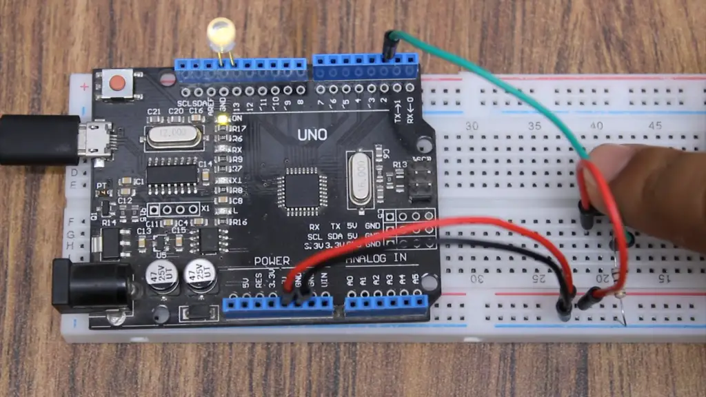
In computing, switch bouncing can also occur when multiple keys on a keyboard are pressed at the same time. This type of bouncing is usually filtered out by the keyboard controller before any data is sent to the computer processor. Without this debounce circuit, individual keystrokes could be misinterpreted as multiple key presses or none at all. Additionally, contact bounce can create noise that disrupts communications between devices attached to an I/O bus or network. Specialized software techniques may need to be employed to reduce this type of interference and allow reliable communication between nodes. Additionally, debouncing can be used on digital logic gates and transistors to ensure that their inputs are correctly recognized by the circuit.
How Does Debouncing Logic Work?
Debouncing logic is used to filter out any false readings resulting from bouncing switches. This type of circuit typically consists of an input signal and a delay timer, which delays the processing of that signal long enough for any bouncing contacts to settle. Once this settling time has elapsed, the switch’s new position can be accurately determined without fear of further interruption.
This technique is useful for both mechanical and electronic switches, as it eliminates the need to use more expensive “bounceless” components in many applications. Debouncing logic can also be used for other types of inputs such as buttons or encoder wheels. Additionally, it can be used to reduce interference on digital buses or networks caused by contact bounces.
In summary, debouncing logic is a simple but effective way to filter out any false readings resulting from bouncing switches. This technique can be used in both mechanical and electronic switches, as well as on digital buses or networks, allowing for more reliable system performance. With careful consideration during circuit design, the effects of contact bounce can be largely eliminated, ensuring the robust operation of the entire system [2].
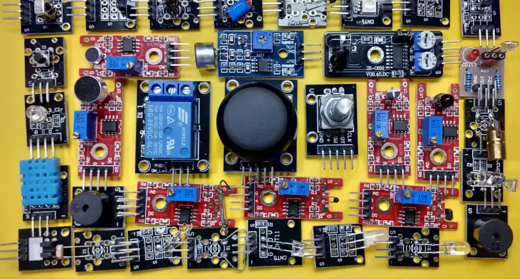
Toggle LED with Button – Arduino Tutorial
Introduction
In this Arduino tutorial, you will learn how to control an LED with a button or switch. This project is fairly simple and can be done in a few steps. With this project, you will be able to turn the LED on and off simply by pressing the button connected to your board! It means you can control the LED with the button and switch it on and off as needed.
Requirements
To complete this Arduino tutorial, all you need are:
– An Arduino Board
– A breadboard
– LEDs
– Wires
– Pushbutton
– 10k ohm resistor
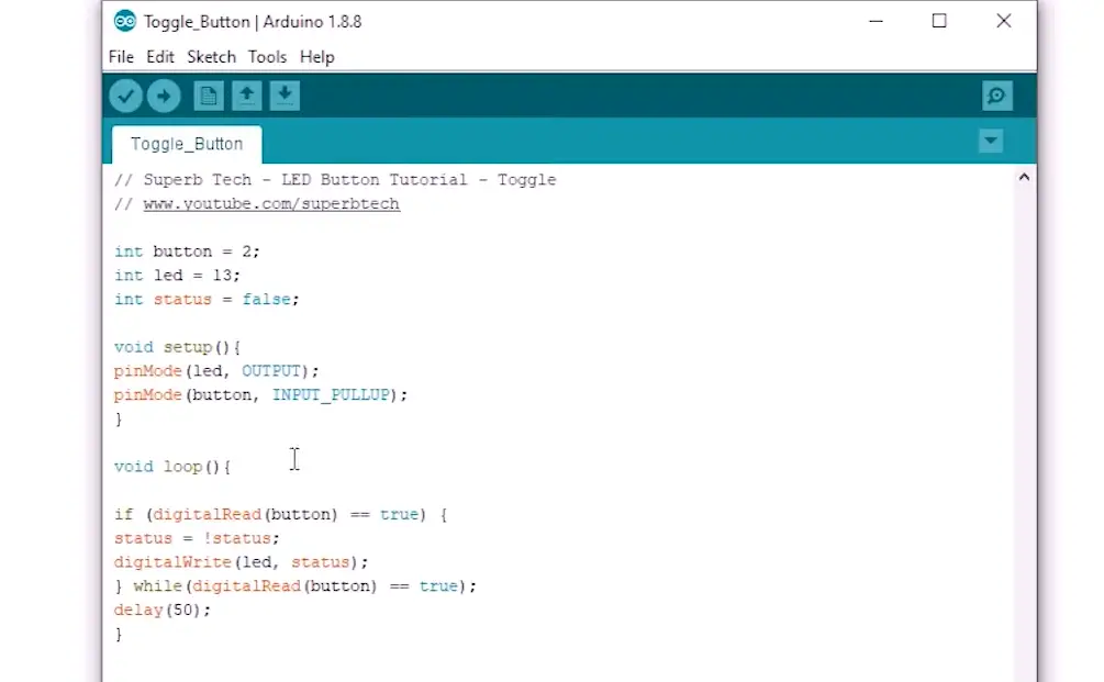
Steps for Toggle LED with Button – Arduino Tutorial
- Start by connecting the ground (GND) pin of both the Arduino board and the breadboard together.
- Next, connect the positive voltage or VCC pin of both the Arduino board and breadboard together.
- On the breadboard, place your pushbutton in a horizontal position with one end connected to GND and the other end connected to Digital Pin 11 on the Arduino Board.
- Connect the 10K ohm resistor from Digital Pin 11 on the Arduino Board to the ground (GND).
- Now place your LED on the breadboard and also connect its negative leg or cathode (-) to GND and its Positive leg or anode (+) to digital Pin 13 on the Arduino Board.
- Finally, upload this code into your Arduino IDE:
“`int buttonPin = 11;
int ledPin = 13;
int buttonState = 0;
void setup() {
pinMode(ledPin, OUTPUT);
pinMode(buttonPin, INPUT);
}
void loop() {
buttonState = digitalRead(buttonPin); //read the state of the pushButton value
if (buttonState == HIGH) { //check if the button is pressed
digitalWrite(ledPin, HIGH); //turn LED ON
delay(100); //delay of 100ms } else { digitalWrite(ledPin, LOW); //turn LED OFF } }“`
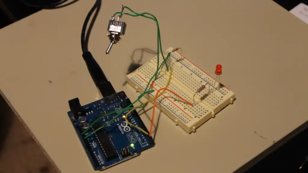
Steps Button Toggle LED with Arduino UNO
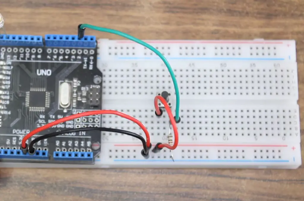
Wiring / Connections
- Connect the Arduino board to your computer using a USB cable.
- Take the positive lead of an LED and attach it to digital pin 13 on the Arduino board.
- Connect the negative lead of the LED to GND (ground) pin on the Arduino board.
- Take one end of a 10K Ohm resistor and connect it to digital pin 8 on the Arduino board, then take the other end of this resistor and connect it to one terminal (the middle pin) of a push button switch.
- Finally, take one wire and connect it from digital pin 7 on the Arduino board to another terminal (any one) of the push button switch, then take another wire and complete this circuit by connecting the other terminal of the push button switch to GND (ground) pin on the Arduino board.
Installing Arduino IDE
- Download and install the Arduino IDE from the official website.
- Once it is installed, open the software and connect your Arduino board to the computer using a USB cable.
Uploading Code to Arduino Board
Copy the following code into a blank sketch in the Arduino IDE:
int LED = 13; //LED connected to digital pin 13
int PushButton = 8; //Push button switch connected to digital pin 8
void setup(){
// set digital pin 13 as output for LED:
pinMode(LED, OUTPUT);
// set digital pin 8 as input for push button switch:
pinMode(PushButton, INPUT); }
void loop(){
if(digitalRead(PushButton) == HIGH){
// Turn LED on:
digitalWrite(LED, HIGH); } else{
//Turn LED off:
digitalWrite(LED, LOW); } }
Select the correct board type and port from the Tools menu of Arduino IDE, then click on Upload button to upload this code to your Arduino board.
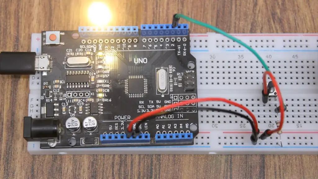
Testing Your Setup
- Once you have uploaded the code to your Arduino board, press the push button switch attached to it and check if the LED turns ON or OFF accordingly. If so, then congratulations! You have successfully completed this project. Now you can experiment with different components to build more complex circuits and projects.
- If the LED doesn’t turn ON or OFF, then check all your connections again and make sure that they are correct.
- Finally, if the problem still persists, then upload the code again. Then, check if the LED turns ON or OFF accordingly. If this doesn’t help, then there might be a problem with your Arduino board and you should get it checked or replaced [3].
What to avoid when Arduino toggling LED with button?
When toggling an LED with a button using Arduino, there are some important things to consider in order to avoid problems:
- Avoid connecting the power supply and ground directly to the LED when toggling it via the button. This could potentially cause a short circuit.
- Avoid using overly complicated wiring schemes that involve too many components or wires. Simple is always best!
- Make sure all connections are secure and firmly attached, as loose connections can cause instability in your system or worse, damage your board or components.
- When programming the code for your project, avoid writing excessively long lines of code that do not follow proper coding principles such as readability and organization.
- Lastly, remember to always disconnect the power supply from your device before making any changes or additions to the circuit board! This will help you avoid any potential damages that could occur due to incorrect wiring or programming.
By following these simple tips, you can be sure that your Arduino LED and button project will be successful and free from problems.
FAQ
How to Debounce Switches With Hardware?
One of the methods for debouncing switches is to use a capacitor and resistor in series with the switch. The capacitor charges up when the switch is closed, providing a short delay before it sends a signal to the microcontroller. When the switch opens, the capacitor discharges slowly, giving time for any bouncing signals from the switch to settle before sending them off. This type of circuit can also be used to filter out high-frequency noise that may be picked up by the incoming signal line.
Another method involves adding an external timer circuit that will take care of any bouncing signals and provide an output only after all other signals have settled. This works well when dealing with multiple switches or in systems where speed is not critical.
Finally, some microcontrollers have built-in hardware that can be used to debounce switches. By setting up the timer and counter values, these devices can detect any bouncing signals and filter them out before they reach the main program. This eliminates the need for external components and is usually faster than other methods.
In general, it is best to use whatever method works best for your particular application. Each has its advantages and disadvantages, so it pays to do some research before making a selection. No matter which method you choose, taking steps to ensure proper switch debouncing will help make sure your device responds as expected when interacting with the user.
Can I Debounce Switches Using Software?
Yes! Another way of debouncing switches is to use software. This involves writing code that will detect any bouncing signals from the switch and eliminate them before they reach the main program. Although this method may be more time-consuming and require more processing power than hardware solutions, it can still work quite well in certain applications.
For example, if you’re working with a microcontroller that doesn’t have built-in hardware for debouncing switches, then using some simple software algorithms can be an effective way of filtering out any bouncing signals from the switch. The code should also take into account any potential latency issues caused by slower responses from the microcontroller when dealing with multiple switches or timed events.
How to Connect a Schmitt Trigger to the Arduino?
The Schmitt trigger is a type of voltage comparator circuit that can be used to filter out high-frequency noise or bouncing signals from a switch. It works by comparing the input voltage with two threshold values and produces an output when either one is exceeded. This makes it ideal for debouncing switches since it will ignore any signals that fall within its hysteresis band.
To connect a Schmitt trigger to the Arduino, you’ll need to use some external components like resistors and capacitors. The exact values used will depend on your particular application, but generally speaking, you’ll want to use two equal-valued resistors connected in series between the signal line and ground. You’ll also want to add a capacitor across one of the resistors to add an RC time delay.
Once everything is wired up, you can then connect the output of the Schmitt trigger to one of the Arduino’s digital pins. This will allow it to detect any signals from the switch and filter out any bouncing or noise that may be present. With this setup in place, your Arduino should now be able to accurately read inputs from your switch even when dealing with noisy environments.
Using a Schmitt trigger is a great way to make sure that your Arduino responds properly when working with switches, but there are other ways too. You could also use external hardware like capacitors and resistors or write some code that implements debouncing algorithms.
How to Program a Schmitt Trigger on the Arduino?
If you’re looking for an easy way to implement debouncing on the Arduino, using a Schmitt trigger is probably your best bet. This circuit can be used to filter out any high-frequency noise or bouncing signals from switches and will provide reliable inputs to your microcontroller.
To program a Schmitt trigger on Arduino, you’ll need some basic knowledge of programming and electronics. You’ll also need some additional components like resistors and capacitors that will allow you to properly set up the circuit. Once everything is connected, you can then write code that reads the input voltage from the switch and compares it against two threshold values set by the resistors and capacitors. If either one is exceeded, then an output signal will be sent to the Arduino.
This type of circuit can be used in a variety of applications to provide reliable switch inputs and make sure that any bouncing signals are filtered out before they reach the microcontroller. With a little bit of programming, your Arduino will now be able to accurately read inputs from switches no matter what environment it’s working in.
How to Debounce Switches With Code?
When hardware solutions such as resistors, capacitors, and timers are not available or feasible for a given application, debouncing switches can also be achieved using code. Several different approaches can be taken here; one of the more popular ones is to use a counter system, where each time the switch input changes state it adds up until reaching a certain number before registering an action.
Other methods involve running loops that monitor the switch’s state over a certain amount of time and only take action if there have been no changes within that window. This helps ensure that any bouncing signals from the switch are ignored in favor of stable inputs.
Debouncing switches using code requires some knowledge of programming and software design principles but can be a good alternative when hardware solutions are not available. Many microcontrollers have built-in timers and counters that can be used to implement software debouncing, making it easier for developers to take advantage of this technique without having to worry about external components or complex wiring.
No matter which method you use, taking steps to ensure proper switch debouncing will help make sure your device responds as expected when interacting with the user. With a little bit of planning and some careful implementation, you can make sure that all your switch inputs are handled properly no matter what environment or application they’re being used in.
Why is Switch Debouncing Important?
Debouncing switches is an important part of developing electronic devices that use switch inputs. Without it, device performance can suffer due to false signals or unexpected behavior caused by bouncing signals from the switch. This can range from simple annoyances like incorrect readings in a digital display to more serious problems such as malfunctioning safety features.
It’s also important to note that many microcontrollers are not able to handle the load that comes with processing multiple switch inputs at once without debouncing. Implementing hardware or software solutions for debouncing will help ensure that all your switch inputs are handled properly and without any issues.
Overall, taking steps to properly debounce switches is vital for ensuring reliable and predictable performance from your device. It’s a relatively simple task that can help you avoid many common issues and save you from having to deal with unexpected problems down the line. With some careful planning and implementation, you can make sure that all your switch inputs are handled properly no matter what environment or application they’re being used in.
What Are the Benefits of Debouncing Switches?
Debouncing switches is a great way to ensure reliable performance from devices that use switch inputs. Properly debounced switches will produce more accurate readings, help reduce false signals, and eliminate unexpected behavior caused by bouncing signals from the switch. This will result in more consistent operation for your device as well as increased safety and reliability when dealing with critical applications such as safety features.
In addition, debouncing also helps to reduce the load on microcontrollers that are processing multiple switch inputs at once. With proper debouncing, each switch input can be handled one at a time instead of all at once, which can help free up resources and allow for more efficient operation.
What Are the Different Types of Debouncing?
There are a few different ways to debounce switches, each with its advantages and disadvantages. The most common approach is to use either hardware or software solutions.
Hardware solutions involve adding external components such as resistors, capacitors, and timers to filter out noise from switch inputs. This type of solution is often easier to implement but can require additional parts and wiring that may not always be available or feasible for certain applications.
Software solutions use code rather than external components to achieve the same effect— filtering out bouncing signals from switches. This type of solution doesn’t require any additional parts but does necessitate knowledge of programming and software design principles which may make it more difficult for some users.
How to choose the right debouncing method?
When it comes to choosing the right debouncing method for a given application, the best approach is to consider both hardware and software solutions. If you have access to external components like resistors, capacitors, and timers then a hardware solution may be preferable as it can often be easier to implement than writing code.
However, if you don’t have any of these parts available or they would be too difficult/expensive to include in your design then a software solution might be better suited. This type of solution usually requires more knowledge of programming and software design principles but can provide results without needing additional parts or complex wiring.
Useful Video: Arduino Switches Part 1 | Arduino Uno Zero to Hero Day : 8 | RoboVilla Tutorial Project
Conclusion Paragraph
Arduino toggle switch is a great tool for controlling your circuits. It can be used to easily toggle on and off switches in your circuit, allowing you to control various components with just one button press. Arduino toggle switch is also very versatile and can be used in a variety of projects and applications. In short, Arduino toggle switch is an incredibly useful component to have in any circuit design project. With its easy-to-use setup and wide range of applications, it’s no wonder that this component is so popular among makers all over the world. Thanks to its versatility, Arduino toggle switch makes electrical engineering more accessible than ever before!
References
- https://circuitdigest.com/electronic-circuits/what-is-switch-bouncing-and-how-to-prevent-it-using-debounce-circuit
- https://www.techtarget.com/whatis/definition/debouncing
- https://arduinogetstarted.com/tutorials/arduino-button-toggle-led







Leave a Reply