
Are you curious about the world of Arduino and ADC (Analog to Digital Converter)? Are you looking for an easy way to get started with this fascinating technology? Look no further – with this guide, you will explore the basics of Arduino and ADC and have all your questions answered! Training yourself in these concepts is a great way to open up new opportunities and get ahead in the rapidly advancing tech world. This guide will break down everything you need to know about Arduino and ADC here so that you can begin your journey right away.
What is an Arduino ADC?
An Arduino ADC (analog-to-digital converter) is an integrated circuit used to convert analog signals into digital signals which can be used by microcontrollers and computers. It does this by measuring the voltage of the input signal, then converting it into a value that can be read or interpreted by a computer. The resolution of an Arduino ADC ranges from 8 bits up to 16 bits depending on the specific type used. This means that the output range will vary between 0-255 for 8-bit converters and 0-65535 for 16-bit converters. By having this higher resolution, more precise measurements can be taken from the analog signal being converted. An example of an application where precision is important might include measuring temperature with thermocouples.
Analog-to-digital converters are essential components for any project involving digital control of an analog signal or reading an analog sensor’s output. They can also be used in conjunction with actuators or motors that require specific voltages for operation, such as servos and stepper motors. By using an Arduino ADC, analog signals can be converted into digital values that can be used by a microcontroller or computer to control an entire system.
Overall, the use of an Arduino ADC is essential in any project involving digital control of analog signals or sensors. They are simple to interface with and offer a high resolution for more precise readings. Combined with the relatively low cost of these converters, they make for a great addition to any projects requiring analog-to-digital conversion [1].
Features of Arduino ADC
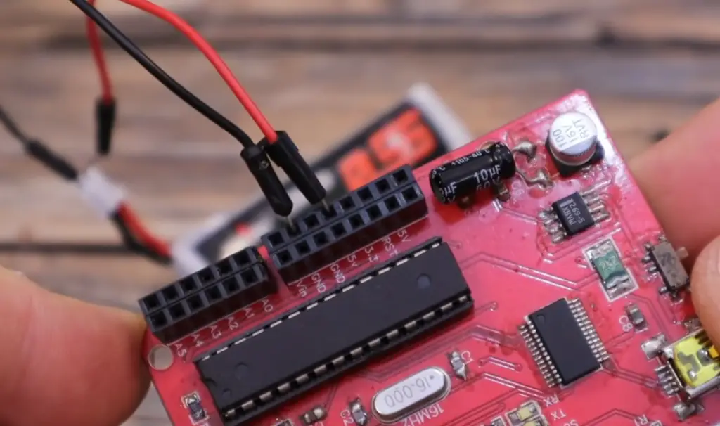
Arduino Analog Pins
The Arduino is capable of reading analog signals through its ADC (Analog to Digital Converter). The ADC is an integrated circuit that converts a continuous physical quantity, such as voltage, current, or pressure into a digital or binary number. Each of the Arduino’s analog pins can read up to five volts and convert it into a 10-bit value between 0 and 1023.
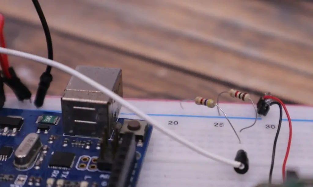
Voltage Divider
The input range of the Arduino’s ADC can be extended using a voltage divider. A voltage divider is an electrical circuit consisting of two resistors connected in series. By connecting the output from the voltage divider to an analog pin on the Arduino, you can measure voltages beyond 5V. This allows you to measure higher voltages, such as those produced by a motor.
Sampling Rate
The sampling rate of the Arduino’s ADC determines how fast it can convert analog signals into digital values. The sampling rate is measured in samples per second (S/s) and can range from 10 S/s on the Arduino Uno to 200 kS/s on the Arduino Mega 2560. The faster the sampling rate, the more accurate your readings will be.
Resolution
The resolution of an ADC indicates the precision of its measurements. The resolution is determined by the number of bits used to represent each sample and ranges from 8-bit to 12-bits on Arduino boards. A higher resolution means more precise readings and better accuracy.
Input Impedance
The input impedance of an ADC is the resistance the circuit presents to the incoming signal. The higher the input impedance, the less distortion the signal will experience when passing through the ADC. On Arduino boards, input impedances range from 10 kΩ to 50 kΩ.
Offset Error
An offset error occurs when a reading taken by an ADC deviates from its expected value due to an offset voltage applied to it. This offset voltage can be caused by leakage current or imperfections in the circuit design. Offset errors can be reduced by calibrating your device before taking measurements.
Gain Error
Gain error is caused by an incorrect gain setting in the amplifier of an ADC. This can result in readings that are either too low or too high. To correct for this, you must adjust the gain setting to match the required specification.
Noise
Noise is any unwanted signal that interferes with the accuracy of a measurement. Examples of noise include random electrical signals, static electricity, and electromagnetic interference from nearby devices. The input circuitry on Arduino boards has been designed to reduce the amount of noise present in analog signals.
Temperature Coefficient
The temperature coefficient indicates how much a device’s performance changes when its temperature changes. When using Arduinos, it is important to take into account any temperature-induced errors in your ADC readings. This can be done by calibrating your device at different temperatures or using a temperature compensation circuit.
Arduino ADC Size
The size of the ADC integrated into Arduino boards is determined by the number of pins and components used. Arduinos generally contain an 8-pin ADC with up to 12 pins on some boards. This allows for a smaller board design, which reduces cost and increases portability.
Arduino ADC resolution at 5V
The resolution of the Arduino’s ADC at 5V is 10 bits, meaning it can read values between 0 and 1023. This is sufficient for most applications, but higher resolutions are available on some boards. For example, the Arduino Mega 2560 has a 12-bit ADC which can read values between 0 and 4095 [2].
How the Arduino ADC works
The Arduino ADC works by taking an analog voltage as an input and converting it into a numerical value that can be read by the microcontroller. It does this through a conversion process called “Analog to Digital Conversion” or A/D Conversion. This process involves using a reference voltage, typically 5V, and comparing it against the incoming analog signal. The ADC then measures how much of the reference voltage is taken up by the analog signal and assigns a numerical value to it. This number is then sent to the microcontroller, which can use it for whatever purpose desired.
For the Arduino ADC to work properly with your analog signals, you need to make sure that they are within range of what is accepted by the ADC. This range is typically 0-5V, so any signals beyond this range will not be accurately represented by the ADC. Additionally, you need to ensure that your analog signals are free of any noise or interference as even a small amount can drastically affect the accuracy of the conversion process.
Finally, you also need to make sure that the resolution of your Arduino ADC is sufficient for your needs. The higher the resolution, the more accurate readings you will get from your analog signal. Generally speaking, an 8-bit ADC has enough resolution for most applications but if you need more precision then a 10-bit or 12-bit ADC may be better suited for your project.
Benefits of using Arduino ADC
The main benefit of using an Arduino ADC is that it makes analog-to-digital conversion straightforward. The ADC allows users to read an analog voltage from sensors or other sources, convert it into a digital value, and then use this digital data for further processing. This can be used in numerous applications such as controlling motors, sensing temperature and humidity levels, etc.
Additionally, the ADC on Arduino boards has a wide range of input voltages which helps support more applications than traditional microcontrollers with limited input voltage ranges. Furthermore, the buildup of noise or interference is reduced thanks to its built-in filtering capabilities.
Another advantage of using Arduino ADC is its fast sampling rate which allows for accurate control over devices like servo motors and other applications that require rapid input sampling. Finally, the Arduino ADC has a built-in calibration feature that allows for accurate readings without having to manually adjust settings. This helps speed up development time and makes the user experience more enjoyable.
Overall, using an Arduino ADC provides many advantages over traditional microcontrollers and can be a great tool when it comes to analog-to-digital conversion. It is versatile, easy to use, and provides increased accuracy over traditional methods.
Some mistakes in using Arduino ADC
- Not accounting for noise: The analog-to-digital converter (ADC) in Arduino can be susceptible to interference due to external electrical noise. It is important that the user accounts for this when taking readings and implements noise filtering techniques if necessary.
- Incorrect reference voltage: When taking measurements with the Arduino ADC, it is important to ensure that the reference voltage is set correctly. If it is not set properly, then inaccurate readings may result from the conversion process.
- Improper grounding: Grounding is an essential part of any electrical circuit, and it should be given extra attention when using the Arduino ADC. Poorly grounded circuits can lead to inaccurate readings or even permanent damage to your device.
- Ignoring offset errors: Offset errors can occur when the Arduino ADC is used to read small signals. These errors can be minimized by using proper calibration techniques and/or increasing the resolution of the conversion process.
- Overloading the analog input pins: When taking multiple readings with the Arduino ADC, it is important to make sure that each pin does not exceed its maximum voltage rating. Doing so could cause permanent damage to your device and lead to inaccurate readings.
- Not accounting for temperature variations: Temperature changes can have a significant impact on the accuracy of measurements taken with an Arduino ADC. If possible, try to use temperature compensation techniques or keep ambient temperatures stable to ensure more accurate results.
- Using an inadequate power supply: A sufficiently powerful power supply is needed to ensure that the Arduino ADC works properly and takes accurate readings. Make sure to use a power supply with enough current capacity for your device.
- Not configuring the correct timing parameters: Configuring the wrong timing parameters can lead to inaccurate results or even permanent damage to your device. It is important to make sure that all settings are correct before attempting any measurement with the Arduino ADC.
- Failing to check input voltages: Input voltages must be closely monitored when working with an Arduino ADC, as they can cause incorrect readings if not kept within their specified limits. Always double-check voltage levels before taking any measurements.
- Using outdated components: Arduino ADC technology can be prone to obsolescence, so it is important to check if your device is compatible with the latest components or firmware updates. This will ensure that your readings are as accurate as possible.
- Not calibrating properly: Proper calibration of the Arduino ADC is essential for taking accurate measurements. Without proper calibration, inconsistent results may occur due to drift or noise in the circuit. Make sure to follow all necessary steps when calibrating your device before taking any readings.
- Overlooking safety precautions: Even though the Arduino ADC is designed for use by hobbyists and enthusiasts, it still requires certain safety measures to be taken while operating it. Always make sure you have followed all safety regulations before attempting any measurements with your device.
- Not considering power consumption: Power consumption should always be taken into consideration when using the Arduino ADC, as it can easily draw more current than necessary and lead to inaccurate readings or even device damage. Make sure to use only the amount of power required for your application.
- Ignoring environmental factors: Environmental factors such as humidity, dust, and temperature changes can have a significant effect on the accuracy of measurements taken with an Arduino ADC. If possible, take steps to minimize their impacts or account for them in your results.
- Not testing thoroughly: It is essential to test all aspects of your circuit before taking actual measurements with the Arduino ADC. This will ensure that everything is working properly and will help you get more accurate results.
- Not using the right type of shield: Depending on your application, you may need to use a specific type of shield with the Arduino ADC. Make sure to check which shields are compatible with your device before attempting any measurements.
- Using outdated libraries: It is important to make sure that all libraries used for controlling or interfacing with the Arduino ADC are up-to-date, as older versions can contain bugs or other issues that could lead to inaccurate readings.
- Ignoring temperature limits: The operating temperature range of an Arduino ADC should always be taken into consideration when taking readings, as temperatures outside this range can cause inaccurate results or even permanent damage to your device.
- Not understanding the data format: Make sure you understand the data format used by the Arduino ADC so that you can properly interpret your results and make use of them in your application.
- Failing to account for voltage drops: Voltage drops can occur when taking readings with the Arduino ADC, leading to inaccurate measurements. This is especially important when measuring low voltages, as even small voltage drops can affect your results significantly. Be sure to consider this when using your device.
FAQ
Is there an ADC in Arduino?
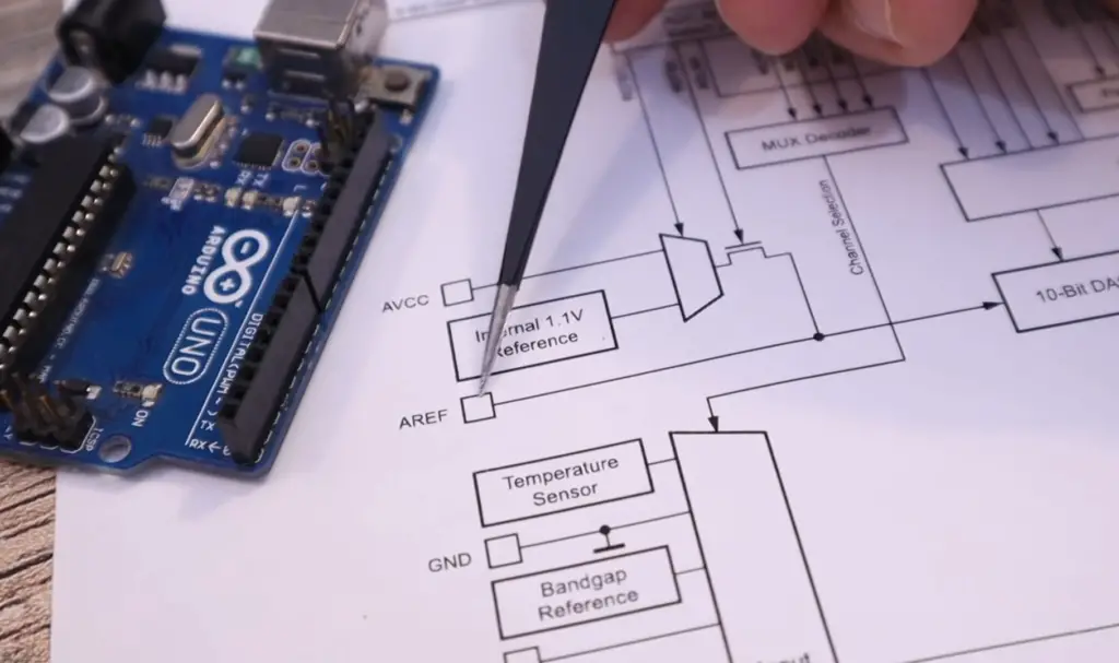
Yes, Arduino does have its own ADC. It can be used to read analog signals and convert them into digital values that can be processed by the microcontroller. The ADC of an Arduino can measure voltages up to 5V with a resolution of 10 bits, which means it has 1024 possible values. Additionally, it has an in-built reference voltage of 1.1V that can also be used for more precise readings. The ADC on Arduino is very useful for measuring sensors such as temperature, light, humidity, etc., which require analog input signals to function correctly.
Do I need additional components to use the Arduino ADC?
No, you do not need any additional components to use the ADC on an Arduino board. However, you may need some additional components, depending on your project. For example, if you plan to measure AC voltages or high voltages, then you will need an external voltage divider or level shifter to reduce the input voltage to a level that can be safely read by the ADC. Additionally, if you are measuring very low voltages, then you might need an amplifier circuit to boost the signal before feeding it into the ADC.
What is the maximum sampling rate of Arduino’s ADC?
The maximum sampling rate of the Arduino’s ADC is 15kHz. This means that it can sample up to 15000 times per second and convert analog signals into digital values at that speed. The resolution of each reading is 10 bits, which is quite high for an 8-bit microcontroller like Arduino.
What is the accuracy of Arduino’s ADC?
The accuracy of the ADC on Arduino boards is quite good. The resolution of 10 bits allows for 1024 possible values and therefore very fine measurements. Additionally, the built-in reference voltage of 1.1V provides more accurate readings than using a fixed external reference voltage from a power supply or battery. Overall, the accuracy of Arduino’s ADC can be considered to be reliable and suitable for most applications.
Can I use an external ADC with Arduino?
Yes, you can use an external ADC with your Arduino board if needed. This could be useful if you need a higher resolution or faster sampling rate than the Arduino’s ADC can provide. Additionally, it could be used if you need to measure something that requires a different voltage range than the 5V limit of Arduino’s ADC. There are many different types of ADCs available on the market and they all have their own advantages and disadvantages so make sure you do your research before making a purchase.
Can I use an Arduino board to read digital signals?
Yes, an Arduino board can be used to read digital signals as long as the signal is within its operating voltage range (5V). The microcontroller on the board can detect when a pin goes from high to low or vice versa and take appropriate action based on that input. This makes it very useful for building projects such as robots and automated systems. Additionally, you can use the Arduino board to read serial data from other devices as well.
Finally, some Arduino boards also have external interfaces such as I2C or SPI that allow them to communicate with special digital sensors. This makes it even easier to connect more complex digital components to your project.
What is the ADS1115 ADC module?
The ADS1115 is an analog-to-digital converter (ADC) module specifically designed to be used with Arduino boards. It is a 16-bit ADC that can measure up to four different analog inputs and convert them into digital values for further processing by the microcontroller. The module communicates over I2C so it requires little in the way of wiring or external components, making it a great choice for projects that require high accuracy measurements. Additionally, this module is capable of running at data rates of up to 860 samples per second, which makes it perfect for applications where speed matters.
What is the difference between ADS1115 and Arduino ADC?
The main difference between the ADS1115 and Arduino ADC is resolution. The ADS1115 has a resolution of 16 bits, meaning it can measure up to 65536 different values, while the Arduino’s ADC is only 10-bits, meaning it can read up to 1024 different values. Additionally, the ADS1115 also supports faster sample rates than what an Arduino board can provide on its own. Finally, the I2C interface makes wiring and connections much more straightforward compared to having to use multiple pins for analog inputs with a standard Arduino board.
How to use an ADC with Arduino?
Using an ADC with Arduino is fairly straightforward. All you need to do is connect the pins of the ADC module to the pins of the Arduino and then write a few lines of code to read data from it. The exact setup will depend on which type of ADC module you are using, but generally, all modules will have power and ground connections as well as at least one analog input pin. You’ll also need to configure your code for selecting the proper gain and reference voltage for your project. Once everything is connected and configured, you can then start collecting readings from your ADC module.
Should ADC be divided by 1023 or 1024?
When measuring analog signals with an ADC, it is important to note that the maximum reading you can get will be 1023 or 1024 depending on the resolution of your ADC. For example, if you are using a 10-bit ADC, then you should divide the measured value by 1023. If you are using a 16-bit ADC, then you should divide the value by 1024 instead. This will help ensure that your actual measurements match up with what your code expects them to be.
What is oversampling in Arduino?
Oversampling in Arduino is a technique used to increase the accuracy and reliability of readings taken from an analog sensor or other source of input. It involves taking multiple samples of the same signal at different points in time and then combining the results to get a more accurate reading. By using this method, you can reduce noise that may be present in the signal and also increase the resolution of your readings if needed. There are several different algorithms for calculating an average from multiple samples, so make sure to research which one is best for your project before implementing it.
Useful Video: ADC blocks and REGISTERS | Internal Reference | Internal Temperature Sensor Arduino101
Conclusion Paragraph
Arduino ADC is a powerful tool for measuring and controlling analog signals. Its simple hardware setup, diverse capabilities, and open-source nature make it an ideal choice for many applications. With its integrated microcontroller, Arduino ADC is capable of executing complex commands with ease. The miniaturization of components has also enabled the device to be used in more compact spaces while still providing excellent performance. All these features make Arduino ADC a great option for adding reliable analog sensors to any project or system.
References
- https://www.digikey.com/en/maker/projects/learn-to-use-the-arduinos-analog-io/d3215f289c714847a6576a73717cd161
- https://www.best-microcontroller-projects.com/arduino-adc.html
- https://linuxhint.com/use-adc-arduino/