
Do you want to learn all about BCD Counters? If so, you’ve come to the right place! In this comprehensive guide, we will answer common questions and provide useful tips on how to use BCD counters effectively in your designs. We’ll start with a brief overview of what BCD counters are, followed by a discussion on how they work. Then, we’ll explore some of the benefits of using BCD counters and finish up with a few tips on getting started. Are you ready to unlock the power of BCD counters? Let’s get started!
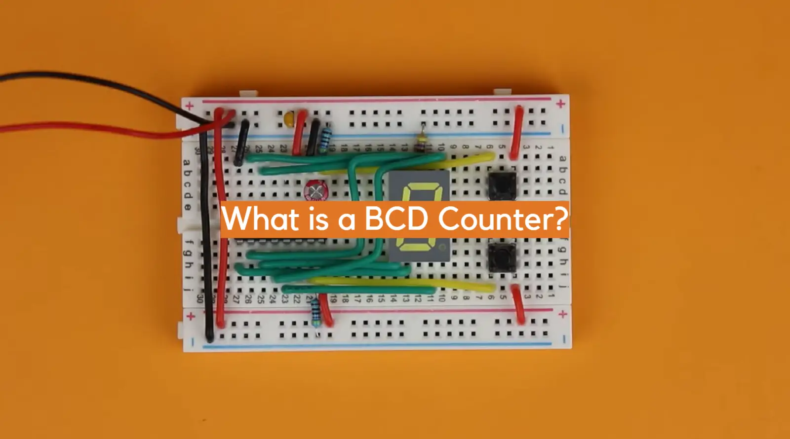
What is a BCD Counter
However, instead of outputting decimal digits (0-9), it outputs binary coded decimal digits (BCD). BCD counters use four bits to represent each digit, i.e0-9 are represented by 0000 through 1001 in BCD.
BCD counters have many uses in electronics applications such as counting the number of pulses produced by a motor, events recorded over time intervals and counting occurrences within a given period of time. They can also be used for detecting errors in communication protocols or for data conversion from one format to another.
BCD counters are usually built out of flip-flops and logic gates. The most basic type contains four D flip-flops connected in series with some additional logic to convert the data from binary to BCD format. In order to make the counter count up sequentially each time it is triggered by an input signal, a clock signal must also be applied.
In order to use a decade counter, an input signal must be given in order to advance the count from 0-9 every time it is triggered. This can be done using either a clock signal or by connecting other digital circuits such as encoders or multiplexers.
At REST mode, the device’s decade counter is reset to ‘0’, which translates to 0000 in binary. This customarily marks the start of a new cycle for this type of counter. When an incoming clock signal is connected to the circuit, it begins counting binary digits in a row. The circuit can count up to 9 digits or 1001 with only one initial pulse of the clock. As soon as another wave of this clock arrives, the count increases to 10 – that’s 1010!
The output of the BCD counter can be connected to a decoder circuit in order to display the number it is counting. This makes it especially useful for applications that need to display numeric data on an LCD or LED panel.
BCD counters are relatively easy to program and configure, making them ideal for use in embedded systems. They can also be used in conjunction with other digital logic circuits for more complex projects. [1], [2], [3]
74LS90 Decade Counter IC Description
The 74LS90 is a popular BCD decade counter integrated circuit (IC). It was designed to count up or down in binary coded decimal format and can be used for a variety of counting applications such as motor speed measurement and control, event counting, pulse-width modulation (PWM), frequency division, etc.
This IC contains four D flip-flops internally connected in series along with logic gates to convert the data from binary to BCD format. Each flip-flop stores one bit of the BCD output which makes up one decimal digit. Each time the chip receives an input signal, it advances its internal state by one count.
Now let’s take a look at the 74LS90 pinout. It has 14 pins. Let’s take a look at them!
The pins are part of an electronic component and their functions are described as follows:
- Pin 1 is named CLKB, which stands for Second Clock Input. It is used to provide the second clock signal input to the component.
- Pin 2 is R1, which is the Reset 1 pin. When a signal is applied to this pin, it resets the component’s internal state.
- Pin 3 is R2, the Reset 2 pin, which functions similarly to R1.
- Pin 4 is NC, which means “No Connection.” This pin is not used and is typically left unconnected.
- Pin 5 is Vcc, which is the positive input supply pin. It is used to provide power to the component.
- Pin 6 is R3, the Reset 3 pin, which is used to reset the component’s internal state.
- Pin 7 is R4, the Reset 4 pin, which functions similarly to R3.
- Pin 8 is named Qc, which is the third output pin. It is used to provide the third output signal from the component.
- Pin 9 is Qb, the second output pin. It is used to provide the second output signal from the component.
- Pin 10 is Gnd, which is the ground pin. It is used to provide a reference voltage for the component.
- Pin 11 is Qd, the fourth output pin. It is used to provide the fourth output signal from the component.
- Pin 12 is Qa, the first output pin. It is used to provide the first output signal from the component.
- Pin 13 is also NC, which is not used and is typically left unconnected.
- Pin 14 is CLK A, which is the First Clock Input pin. It is used to provide the first clock signal input to the component.
When using the 74LS90, it is important to take note of the pin layout. Every project that utilizes this component should be designed with the pin layout in mind. This will help ensure proper functioning of the component and optimal performance. Additionally, it is important to check the datasheet for details on how to use the component under different conditions, such as varying input frequencies or power supply voltages. [1], [2], [3]
Applications of BCD Counters or Decade Counters
BCD counters and decade counters can be used in a variety of applications. This is due to their ability to count numbers accurately and quickly, as well as their flexibility in terms of programming and configuring them for a variety of tasks.
State machines
One common application of BCD counters is to implement state machines. A BCD counter can keep track of the current state of a system, incrementing by one for each state change. The outputs of the counter can then be decoded to perform actions or control outputs based on the current state. This is useful for sequencing operations or events.
Clock circuits
Another of the most common applications for BCD counters is to create clock circuits. The counter can be used to count the number of cycles in a specific period, and then generate pulses at set intervals. This helps with timekeeping, synchronization, and other aspects of timing within an electronic system.
Frequency dividers
Frequency dividers are one of the most common applications for BCD counters and decade counters.
In this technique, each signal is assigned a different frequency range over the transmission medium. The frequency ranges are separated sufficiently so that they do not overlap. This allows the signals to be separated at the receiver and demodulated into the original information.
Frequency dividers can be used to reduce a high-frequency clock signal into a lower frequency that can be used to control or trigger other operations, such as time delays or pulse width modulation (PWM).
Sequencers
BCD counters can be used as sequencers.
BCD counters can be programmed or configured to count in a specific sequence and produce outputs for each count. This can be useful for controlling a sequence of events or steps in a process. The counter can be reset once the sequence is complete to repeat the sequence again.
Clock division
Next, BCD counters can be used to divide a clock signal. They can count up to 9,999 events (for a 4-digit BCD counter) before overflowing and resetting back to zero. This makes them useful for applications where approximate event counts are sufficient and high precision is not required. The outputs of the BCD counter can be connected to a display to show the current event count in BCD format. This is a simple and cost-effective way to implement an event counter.
Integrated oscillators
BCD counters can be used to control oscillators and timers. Integrated oscillators are electronic circuits that generate periodic signals, such as sine waves or square waves, from a direct current power supply. They contain active components such as transistors or op amps that provide the necessary feedback to create an oscillator.
BDDs can be configured to count up to a specific value and then output a pulse or trigger, which can then be used to control an oscillator. For example, they can be used to produce a pulse output every 10 seconds or 100 seconds by configuring the counter to count to the desired value.
Clock generation
Lastly, BCD counters can be used to generate clocks and timing signals. By connecting a free-running oscillator to the clock input of a BCD counter, it will count the cycles of the oscillator.
The counter can be configured to reset and trigger an output pulse after counting to a specific value. By selecting different count values, clock signals with various frequencies can be generated. This is useful for timing and synchronization circuits. [1]
FAQ
What is a BCD counter also known as?
BCD (Binary Coded Decimal) counters are also commonly referred to as decade counters or binary decade counters. They are digital circuits that count from 0 to 9 and then rollover back to 0 again. The output of the counter is in BCD format, which means it counts in 10’s instead of using a conventional binary counting pattern.
BCD counters are used in many technological applications and devices, such as calculators, watches, digital clocks, keypads, and more. They are also useful for addressing multiple outputs from a single input. As BCD counters count up to 9 before resetting to 0 again, they are very efficient when it comes to dealing with data that must be kept track of in groups of 10’s, such as for financial calculations.
Where are BCD counters used?
BCD counters are commonly used in digital systems and circuits where binary values need to be converted and displayed in decimal format. Some common applications of BCD counters include:
- Digital clocks and timers: BCD counters are used to keep track of time in units of hours, minutes and seconds which are decimal values. The binary output of the counter is then decoded into decimal digits to display the time.
- Digital voltmeters: BCD counters are used to count pulses proportional to an analog voltage input. The binary count is then decoded into decimal digits to display the voltage reading in decimal format.
- Channel selection in digital systems: BCD counters are used to sequence through a set of channels or states, with the binary count being decoded into decimal channel numbers for selection.
What does BCD counter mean?
It is an important component in digital circuits and computers, as it can be used for counting purposes or to control other devices.
BCD counters are capable of counting from 0 to 9 and resetting to zero when it reaches 9. They can also be configured to count from any starting value up to the maximum value by adjusting their initial state with preset input pins.
What is the difference between the binary counter and the BCD counter?
This counter has two outputs: one represents the counting state and the other output is used to detect when that limit has been reached.
On the other hand, BCD (Binary Coded Decimal) counters are digital devices which convert decimal numbers into their binary equivalents and can count up to nine without resetting after reaching this value. BCD counters have four outputs – A, B, C and D – which represent each digit of the decimal number it’s counting. Unlike its binary counterpart, once a BCD counter reaches ‘9’ it resets itself back to ‘0’ and continues counting up.
BCD counters are often used in industrial and consumer applications such as digital clocks, vending machines, microwaves, car odometers and instrumentation systems. They are considered more accurate than binary counters due to the fact that they can count higher numbers without resetting. Therefore, if accuracy is a priority, then a BCD counter would be your best option.
How is the BCD counter called?
The BCD counter is also known as the Binary Coded Decimal Counter. It is a type of digital counting circuit that counts in decimal (base 10) by converting each decimal digit into binary code before performing the counting operation.
What is the purpose of a binary counter?
A binary counter is a type of digital circuit used for counting applications. It is the most commonly used type of counter in digital circuitry and has various applications such as timekeeping, frequency measurement and other types of counting operations.
Binary counters are also sometimes referred to as “BCD” or binary-coded decimal counters because they typically store data in a BCD format (binary-coded decimal). This means that each digit within the counter is represented by four bits of information, making it easier to read and interpret the stored count.
The purpose of using a binary counter is essentially twofold: firstly, to keep track of how many times an event has occurred; secondly, to be able to set a specific limit or boundary for when the count should stop (for example, a timer or frequency counter).
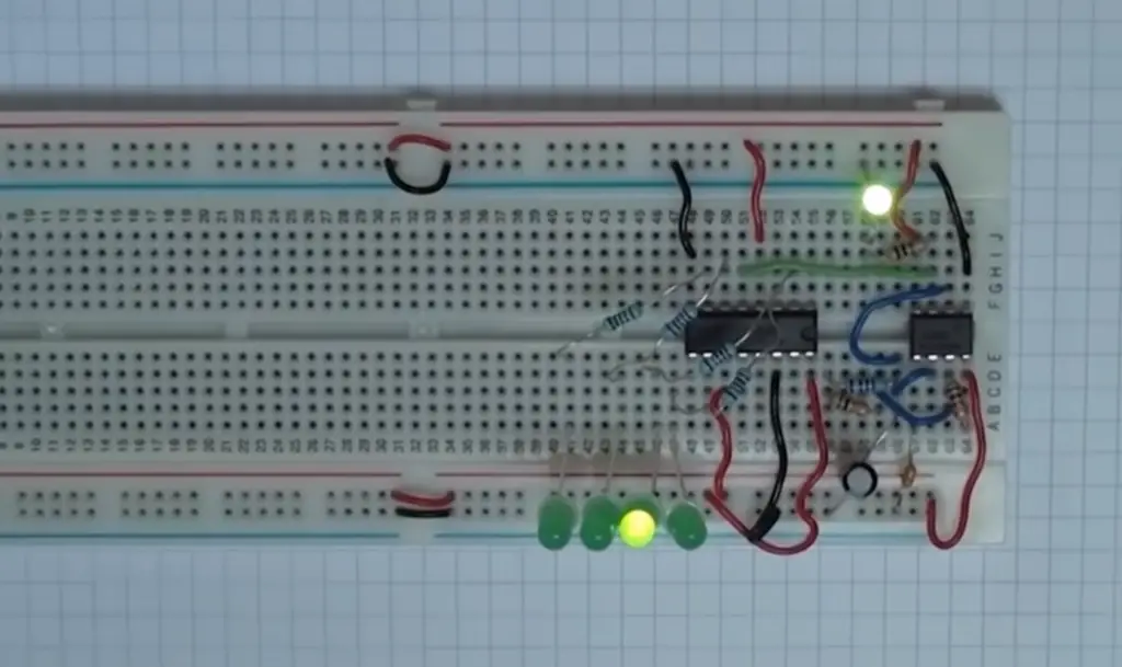
Useful Video: Binary Counter LED Circuit
Conclusion
BCD counters are a useful tool for counting in binary-coded decimals. By understanding the basics of BCD counters, like how and why they work, you can easily use them to accurately count up or down in Binary Coded Decimal (BCD). With the help of this article, you now understand how to determine the number of inputs and outputs for a BCD counter and what the common types are. You also know how to choose which type is best suited for your application. Lastly, we discussed some tips on using BCD counters that will make your life easier when dealing with digital electronics.
In this article, we’ve seen how to use BCD counters for counting in binary-coded decimals. We hope that you now have an understanding of this useful tool and can leverage it in your projects. No matter if you’re new to digital electronics or a seasoned expert, having a good understanding of BCD counters can be beneficial in many applications. With the information provided in this article, you now have the necessary knowledge to make informed decisions when designing or using BCD counters. So don’t be afraid to try out BCD counters for your next project!
We hope that this guide has given you a good understanding of what a BCD counter is and how it functions. Good luck with all your digital engineering projects!
This concludes our Epic Guide on BCD Counters – we hope you found it useful!
References
- https://www.elprocus.com/bcd-counter-circuit-working/
- https://www.watelectronics.com/bcd-counter-design-operation/
- https://www.electronics-tutorials.ws/counter/bcd-counter-circuit.html