
Do you know the difference between a transistor and a resistor? If not, don’t worry! You’re not alone. In this article, we will discuss the differences between transistors and resistors in detail. We’ll answer common questions about these components, and provide tips for choosing the right one for your needs. So whether you’re just starting out in electronics or you’re a seasoned pro, read on to learn more!
What is a Transistor?
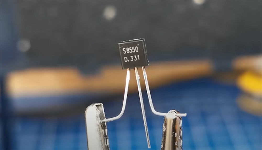
A transistor is a three-terminal semiconductor device that can be used to amplify or switch electronic signals. The term transistor was coined at Bell laboratories by three inventors.
The first practical transistor was invented in 1947 by William Shockley, one of the inventors. Transistors are made from materials like germanium and silicon. They are found in almost every type of electronic equipment today, including radios, computers, and cell phones. [1]
Types of transistors
Transistors come in two main types: bipolar junction transistors (BJT) and field-effect transistors (FET).
BJT transistors
BJT transistors have three terminals: the base, the collector, and the emitter. The majority of BJT transistors are NPN, which means that the current flows from the collector to the emitter when a voltage is applied to the base. PNP transistors work in the opposite way; current flows from the emitter to collector when a voltage is applied to the base. [2], [3]
FET transistors
FETs are made of three regions: source, drain, and gate. The current flow between the source and the drain is controlled by the voltage applied to the gate.
There are two types of FETs: n-channel and p-channel.
An n-channel FET has a channel composed of electrons, while a p-channel FET has a channel composed of holes.
How transistors work
A transistor always has three terminals: the base, the collector, and the emitter. The base is the control terminal, and the collector and emitter are the output terminals. The collector-base junction is reverse biased, and the emitter-base junction is forward biased.
The operation of a transistor can be explained by a three layer system. Two of the layers are doped with the same conductor, while the layer between them is doped with a different type of conductor. When the transistor is off, there is no current flowing between the collector and emitter.
 In my estimation, a transistor’s three terminals—base, collector, and emitter—form a critical trio. The reverse-biased collector-base junction and forward-biased emitter-base junction enable controlled current flow. Understanding the transistor as a three-layer system aids in grasping its operational dynamics, with no current flow when the transistor is in the off state.
However, when a voltage is applied to the base terminal, it creates a current between the collector and emitter terminals. This current is called the collector current, and it is proportional to the voltage applied to the base terminal. The collector current can be controlled by changing the voltage applied to the base terminal.
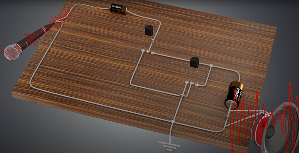
The transistor can be used as an amplifier by applying a small signal to the base terminal. This will create a larger signal between the collector and emitter terminals. The transistor can also be used as a switch by applying a large enough voltage to the base terminal. This will turn on the transistor and allow current to flow between the collector and emitter terminals. [5]
Applications of Transistors
The transistor has many applications, including amplification, signal conditioning, and switching. It is used as an active component in electronic circuits. Many digital and analog integrated circuits use transistors.
Amplification
A transistor can be used as an amplifier by applying a small signal to the base terminal. This will create a larger signal between the collector and emitter terminals. The transistor can be used as a linear amplifier or as a switch depending on the circuit configuration.
Switching
Transistors are also used as switches. A small current or voltage applied to the base terminal can control a much larger current flowing between the collector and emitter terminals. This property can be used to turn electronic devices on and off, or to switch one circuit element in or out of another circuit element. Transistors are widely used as digital switches because they can be turned on or off very quickly, allowing them to operate at high speeds. [6]
What is a Resistor?
A resistor is an electrical component that limits or regulates the flow of current in an electronic circuit and creates resistance. Resistors can be used to create voltage dividers, terminate transmission lines, and filter noise from power supplies. [7]
How Resistors Material Affects Resistance
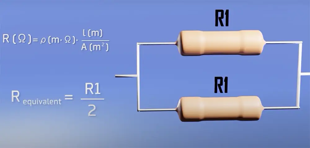
The resistivity of a material is dependent on many factors, including the material’s atomic structure, impurities, and temperature. One of the main reasons for that is electrons! They are the particles in an atom that carry electric charges. The more free electrons a material has, the better it conducts electricity. Metals have a lot of free electrons because their atomic structure allows them to easily lose them. This is why most metals are good conductors of electricity. On the other hand, insulators have very few free electrons because their atomic structure does not allow them to lose them easily.
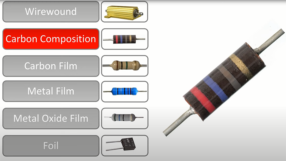
Metal film resistors are made of metal deposited on a ceramic substrate. They have a better resistance than carbon resistors and also are more stable.
Wirewound resistors are made of a wire wound around a ceramic or metal core. They have the highest resistance and are often used for applications that require high power. [11], [14]
How Resistors Work?
A resistor is a two-terminal passive component that implements electrical resistance as a circuit element. In electronic circuits, resistors are used to control the current flow, to adjust the voltage level, and to divide voltages. A resistor’s value is measured in ohms and it is symbolized by the Greek letter ω (omega).
Resistors can be made of different materials, including carbon composition, metal film, metal oxide, wirewound, or surface mount devices. The most common type of resistor today is the carbon-composition resistor.
When a voltage is applied across a resistor, a current will flow through it. This current is proportional to the voltage applied across the terminals of the resistor (Ohm’s law). The proportionality constant is called the resistance R, and it is measured in ohms (Ω). For example, if a voltage of V=100 volts is applied across a resistor with resistance R=20 Ω, then the current flowing through the resistor will be I=V/R=100/20=0.005 amperes or “500 mA”.
The power dissipation of a resistor may be calculated using Joule’s law:
P = I²R = V²/R
where P is the power dissipated by the resistor in watts, I is the current flowing through the resistor in amperes, and V is the voltage drop across the resistor in volts.
For example, if a voltage of V=100 volts is applied across a resistor with resistance R=20 Ω, the power dissipated by the resistor will be P=V²/R=(100)²/(20)=500 mW or “500 milliwatts”.
Resistors can be used to create different voltages in a circuit by using them in series or parallel. Resistors in series will have the effect of adding the resistances together. For example, if you have two 100 ohm resistors in series, the total resistance would be 200 ohms. [8], [9], [10]
Applications of Resistors
Types of Resistors
There are many different types of resistors available on the market, each with its own unique set of capabilities. But they can be generalized by two categories: fixed and variable.
Fixed resistors
A fixed resistor is a type of resistor whose resistance value cannot be changed. The widely used type of fixed resistor is the carbon-film resistor, which is composed of a carbon film deposited on an insulating substrate. Fixed resistors are used in circuits where the desired resistance value is known and constant.
Variable resistors
Variable resistors, on the other hand, are designed to have their resistance values changed. The most common type of variable resistor is the potentiometer, which consists of a resistive element and a wiper that can move along the element to change its resistance. Variable resistors are used in applications where the circuit needs to be adjustable, such as volume control knobs and light dimmers. [8]
There are many types of variable resistors, we will discuss three of them.
Potentiometer
A potentiometer is a three-terminal resistor whose resistance can be adjusted by moving the slider along the resistive element. The position of the slider determines the resistance between the terminals. Potentiometers are used in a wide variety of applications, such as volume control knobs and light dimmers.
Potentiometers can be linear or logarithmic. Linear potentiometers have a linear relationship between the resistance and the slider position, while rotary potentiometers have a logarithmic relationship.
The first common type of potentiometer is the linear potentiometer, which has a linear relationship between the position of the slider and the resistance. Linear potentiometers are used in applications where precise control is not required, such as audio volume control.
The second type of potentiometer is the rotary potentiometer, which has a logarithmic relationship between the resistance and the slider position. Rotary potentiometers are used in applications where smoother control is required, such as audio volume control. While linear devices are controlled by a slider, rotary potentiometers are controlled by a knob.
The third type of potentiometer is the digital potentiometer, which is a variable resistor that can be controlled by a digital signal. Digital potentiometers perform the same exact functions as analog devices do, but they can’t withstand higher voltages as well. [12], [13]
Rheostat
A rheostat is a two-terminal variable resistor whose resistance can be adjusted by turning the knob attached to the third terminal. Rheostats are typically used to control the current in an electric circuit, as they have a high power rating.
They are also used as fan speed controllers and lighting dimmers. Rheostats are usually made of carbon or metal film deposited on an insulating substrate. [15]
Trimpot
A trimpot, or trimming potentiometer, is a small potentiometer that is used to adjust the resistance in a circuit. Trimpots are often used to calibrate circuits or to compensate for component tolerance.
Trimpots come in three different types: single turn, multi-turn, and slide. Single turn trim pots have a shaft that can be rotated only once, while multi-turn trim pots have a shaft that can be rotated multiple times. Slide trimpots have a slider instead of a shaft, which allows for finer adjustment of the resistance.
Most trimpots are through-hole components, meaning they are designed to be mounted on a printed circuit board (PCB). But there are also surface-mount trimpots, which are designed to be soldered directly onto a PCB.
Trimpots are used in a wide variety of applications, such as volume control knobs and gain pots. They are also used to calibrate circuits or to compensate for component tolerance. [16]
Differences Between Transistors and Resistors
When it comes to electrical components, transistors and resistors are two of the most important. They both have their own distinct functions, and they each play a vital role in how electronic devices work. But what exactly is the difference between these two components? Let’s take a closer look.
Device type
The first thing to note is that transistors are active devices, while resistors are passive devices. This means that transistors can amplify signals, while resistors cannot.
Resistors have a fixed amount of resistance, which means they can only dissipate a certain amount of power. Transistors, on the other hand, can vary their resistance depending on the current or voltage that is applied to them.
This difference is what gives transistors their amplifying properties. By varying the amount of resistance they offer, transistors can control the flow of electricity in a circuit.
Resistors, on the other hand, are not able to do this. They merely provide a fixed opposition to the flow of current. [1], [2], [8], [9], [16]
Working principle
A transistor is a semiconductor device that can amplify or switch electronic signals and electrical power. It is made of three terminals called the base, collector, and emitter.
A resistor, on the other hand, is an electrical component that limits the flow of electric current in a circuit. It is made of two terminals called the endpoints or leads.
The crucial difference between transistors and resistors is their working principle. Transistors use electron flow to amplify or switch electronic signals while resistors use conductor resistance to control voltage and current in a circuit. [1], [2], [8], [9]
Differences in use
Transistors are typically used for amplifying or switching electronic signals. On the other hand, resistors are used to create a voltage drop in a circuit, or to control the amount of current flowing through it. [1], [2], [8], [9]
FAQ
Can a resistor replace a transistor or vice versa?
In most, resistors and transistors aren’t interchangeable. They serve different purposes in a circuit. Resistors resist the flow of current, while transistors can control the flow of current.
In some cases, transistors can be used instead of resistors in the integrated circuit. The reason for that is fairly simple: resistors can take too much space, and for an IC you would need a device big enough to provide a resistance value big enough.
However, if you need help deciding which component to use in your circuit, the correct thing would be to do some research on the internet or ask an expert.
What is the difference between a transistor and resistor and capacitor?
A transistor is a semiconductor device used to amplify or switch electronic signals and electrical power. A resistor is a passive 3-terminal electrical component that implements electrical resistance as a circuit element. A capacitor is a passive two-terminal electrical component that stores potential energy in an electric field.
The main difference between transistors and resistors is that transistors can be used to control the flow of electricity in a circuit whereas resistors cannot. Transistors are made of semiconductor material, whereas resistors are made of metal wire or carbon.
Do I need to always use a resistor and a transistor together?
No, you don’t need to use them together all the time. You can use either one or both of them in your circuit, depending on the application or project you’re working on.
If you need to control or amplify an electrical signal, then you’ll need to use a transistor. If you just need to resist the flow of electricity, then a resistor will do the job just fine.
Transistors are more versatile than resistors, so they offer more possibilities for advanced circuits. However, they’re also more complicated to use, so they might not be the best choice if you’re just starting out.
Does a transistor have resistance?
Yes, a transistor has resistance. However, the resistance of a transistor can be controlled by the amount of current that flows through it. This is why transistors are used as switches in electronic circuits.
Useful Video: Resistors And Transistors
Conclusion
That’s a quick overview of the differences between resistors and transistors. Resistors are passive devices, meaning they can really only act as a current limiter. Transistors are active devices, which means they do have an internal power supply and can be used for amplification or switching. As you start to learn more about electronics, it’s important to understand these basic distinctions so that you can apply them in your projects. Thanks for reading!
References:
- https://www.techtarget.com/whatis/definition/transistor
- https://www.electronics-tutorials.ws/transistor/tran_1.html
- https://www.rs-online.com/designspark/what-is-pnp-transistor-and-its-types
- https://www.rs-online.com/designspark/what-is-fet-a-detailed-guide-on-fet
- https://www.electronics-notes.com/articles/electronic_components/transistor/how-does-a-transistors-works-basics-tutorial.php
- https://www.vedantu.com/physics/uses-of-transistor
- https://eepower.com/resistor-guide/resistor-fundamentals/what-is-a-resistor/
- https://www.circuitbasics.com/what-is-a-resistor/
- https://www.electronics-tutorials.ws/resistor/res_3.html
- https://www.coursehero.com/study-guides/boundless-physics/resistors-in-series-and-parallel/
- https://eepower.com/resistor-guide/resistor-materials/
- https://www.electrical4u.com/potentiometer/
- https://www.analog.com/en/technical-articles/digital-potentiometers-vs-mechanical-potentiometers.html
- https://www.coursehero.com/study-guides/boundless-physics/resistance-and-resistors/
- http://www.electricalterminology.com/rheostat/
- https://eepower.com/resistor-guide/resistor-types/trimpot/
- https://www-robotics.cs.umass.edu/~grupen/503/SLIDES/transistors.html