
Frequency to voltage converter circuits are found in many different electronic devices. They are used to change the frequency of an AC signal into a corresponding voltage. This can be useful for many different applications, such as powering motors or LEDs. In this article, we will discuss the basics of frequency to voltage conversion, and provide some tips on how to design your own converter circuits!
General Definition of Frequency to Voltage Converters
So starting off with a main question, what exactly is a frequency to voltage converter circuit? In simple terms, it is a device that takes an input signal (in the form of a frequency) and converts it into a proportional output voltage. The input signal can be either AC or DC. These devices are also known as FM converters or f-to-v converters. This output voltage can then be used to control various devices or processes.
Frequency to voltage converters are used in a variety of sectors, including automobiles, aerospace, and manufacturing. They’re commonly utilized in devices such as speedometers and tachometers, where they convert the rotational speed of an engine shaft into an electrical signal that can be displayed on a meter. One of the most common uses is in the automotive industry, where they are used to control engine speed. They are also commonly used in audio systems to control the volume level. Other applications include vibration analysis and material testing equipment.
There are different kinds of frequency to voltage converters. These are based on the number of channels, linearity, and the type of input signal. The most common types are single-ended and differential converters.
 Frequency to voltage converters are unsung heroes across industries, powering speedometers and tachometers in automobiles, ensuring smooth engine speed control. They’re not just limited to the road – these converters find homes in audio systems, controlling volume levels, and play essential roles in vibration analysis and material testing equipment. With various types available, from single-ended to differential converters, their versatility is key to their widespread use.
Differential converter: These have two inputs (positive and negative) and one output. The advantage of this type is that it is relatively immune to noise.
Single-ended converter: These have only one input and one output. They are more susceptible to noise but are easier to design and build.
Linearity: This refers to how well the output voltage represents the input frequency. If the relationship is linear, then a doubling of the input frequency will result in a doubling of the output voltage. If it is non-linear, then the relationship is not proportional.
Which type of the FVC circuit is best for your particular application will depend on your specific needs. If accuracy is paramount, then a linear converter is probably your best bet. However, if you need to be able to handle a wide range of input frequencies, then a non-linear converter might be a better choice. [1], [2]
Purpose of Frequency to Voltage Converter Circuits
As we just mentioned, frequency to voltage converter circuits have a wide range of applications in the industry, where it is necessary to convert a signal of varying frequency into a proportional voltage.
These devices are commonly used in speedometers, where they convert the rotational speed of an engine shaft into an electrical signal that can be displayed on a meter. By converting the frequency into a voltage, it becomes easier to control the speed of a motor. This is because the voltage can be varied to change the speed at which the motor turns.
Other common applications for frequency to voltage converter circuits include various tools that analyze vibration and material testing equipment. FVCs can also be used for data acquisition purposes. With their wide range of uses, it is no wonder that they are so popular.
FVC use in security systems
Another use for an FVC is in security systems. By monitoring the frequency of sounds, these converter circuits can be used to detect intruders or break-ins. For example, if there is a sudden increase in frequency, it could be an indication that someone is trying to break into a building.
FVC use in audio processing
They can also be used in audio processing. Audio processing systems use frequency to voltage converter circuits to convert audio signals into proportional voltage outputs. Signal conditioning systems use frequency to voltage converter circuits to condition signals before they are sent to data acquisition systems. Data acquisition systems use frequency to voltage converter circuits to convert input signals into digital values that can be processed by a computer.
FVC use in tachometers
Tachometers are devices that measure the rotational speed of an object. They are commonly used in engines, where they are used to measure the engine speed. Frequency to voltage converter circuits are used in tachometers to convert the rotational speed of an engine shaft into an electrical signal that can be displayed on a meter.
The input signal from the tachometer is typically a square wave or a pulses per revolution (PPR) signal. The output voltage from the frequency to voltage converter is proportional to the frequency of the input signal.
Frequency to voltage converter circuits are also used in other types of meters, such as water meters and gas meters. In these applications, the input signal is typically a magneto-resistive sensor or a reed switch. The frequency to voltage converter produces an output voltage that is directly proportional to the frequency of the input signal. [2], [3], [4]
What Frequency to Voltage Converters Can Receive as an Input Signal
Frequency to voltage converters can take various forms of input signal. The most common type of input signal is a sine wave, but other waveforms are possible as well. The shape of the input signal will affect the output voltage, so it’s important to understand what sorts of waveforms your particular converter can handle. In general, though, you’ll be looking at either AC or DC signals.
AC signals are those that alternate between positive and negative voltages; in other words, they’re not constantly positive or constantly negative. This is the kind of signal that comes out of your wall socket at home. DC signals, on the other hand, are constant; they’re always either positive or negative (but never both).
In addition to pulses, FVC can receive waveforms from other devices like microcontrollers or sensors. These signals might be digital or analog. If you’re not sure what kind of signal your FVC can take, check the datasheet or talk to the manufacturer.
Some devices come with special filters that help them to ignore noise in the input signal. This can be important if you’re working with a very sensitive device, or if you’re trying to measure a very small voltage change. [2], [5], [6]
Main Components of Frequency to Voltage Converter Circuit
The main components of a frequency to voltage converter circuit are an amplifier and a Resistor Capacitor network.
Amplifier
The amplifier is the first stage of the frequency to voltage converter circuit and its purpose is to amplify the input signal. The amplified signal is then sent to the resistor-capacitor network.
The amplifier used in a frequency to voltage converter circuit must have a high gain and a low input impedance. The most common type of amplifier used in these circuits is an operational amplifier, or op-amp.
Operational amplifiers are ideal for use in frequency to voltage converter circuits because they have a very high gain and can be easily configured for either single-ended or differential inputs.
RC circuits
The purpose of the resistor-capacitor network, or RC circuit, is to filter out any unwanted high-frequency components from the amplified signal, which is a key to getting precise results.
The RC circuit is made up of two resistors and one capacitor connected in series. The value of the capacitor is chosen so that it blocks high-frequency signals but passes low-frequency signals.
All these components are stored as functional blocks in the FVC microchip. [6], [7]
How Frequency to Voltage Converter Circuit Works
Now that we know the basics of frequency to voltage converter circuits, let’s take a more in-depth look at how these devices operate.
When an alternating current flows through a conductor, it generates a magnetic field around the conductor. This magnetic field will induce an electromotive force in any nearby conductors. The magnitude of this induced voltage is proportional to the rate of change of the magnetic flux, which is in turn proportional to the frequency of the input signal.
Thus, by appropriately designing the inductor and capacitor values in the circuit, we can get a desired output voltage that is proportional to the input frequency. [2]
Examples of Frequency to Voltage Converter Circuits
Now that we know the basics of how a frequency to voltage converter circuit works, let’s take a look at some examples of these devices.
IC LM2917
The LM2917 is a frequency to voltage converter IC that is widely used in many applications. This chip has a maximum supply voltage of 28V and a maximum input voltage range of 28V as well.
In addition, the chip can double low ripple voltages and has a low output impedance.
This makes the LM2917 ideal for use in motor speed control, engine management systems, monitoring of turbine speed, and so on.
Applications for the LM2917 include:
IC LM555
Another popular frequency to voltage converter ICs is the LM555. This chip is a precision timer that can be used to generate accurate time delays and oscillations. It can also be used as an astable or monostable multivibrator.
The LM555 chip has 8 pins and can be easily configured to construct a FVC circuit. It is widely used in applications such as timers, alarms, pulse generation, etc.
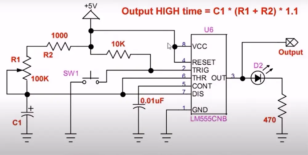
To use this IC as a frequency to voltage converter, we need to connect it in astable mode. In this mode, the IC will generate a square wave output with a duty cycle that can be adjusted using the values of external resistors and capacitors. The output frequency of the LM555 can be calculated using the formula below:
V out = V in x R f x -Ci [4]
IC TC9400
This is a common frequency to voltage converter that is used in many applications. It has a wide range of input frequencies and can be used for both AC and DC signals.
It features a low power consumption and a wide input voltage range, making it ideal for battery-operated devices.
That in addition to the programmable scale factor, makes the TC9400 a versatile chip.
Applications:
- Converting an AC signal to DC
- Measuring frequency
- Analog data transmission
- Monitoring motor speed
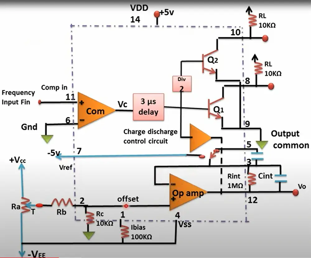
To construct a frequency to voltage converter circuit based on the TC9400 microchip, you’ll need to add a few extra components. These are:
- Integrator op-amp
- One shot circuit
- Charge discharge control circuit
- 3uS delay circuit
- Delay by 2 network
- Drivers
Now, it’s time for a short explanation of how this circuit works. First, the integrator op-amp takes the input signal and converts it into a voltage. This voltage is equal to the output frequency.
The one shot circuit creates a pulse width modulation signal. This signal is then fed into the charge discharge control circuit. The charge and discharge of the output voltage of the integrator op-amp is then being controlled.
The charge discharge control circuit controls the charging and discharging of the capacitor. This controls the output voltage of the integrator op-amp.
The integrator op-amp’s output voltage is then fed into the delay by two networks. This network delays the signal by two clock cycles.
Finally, the drivers take this delayed signal and convert it into a current that can be used to drive a load.
As you can see, with just a few extra components, we can easily create a frequency to voltage converter based on TC9400. [1], [3], [8]
FAQ
What is the main purpose of using a frequency to voltage converter?
The main purpose of using a frequency to voltage converter is to convert an input signal that varies in frequency into an output voltage.
Frequency to voltage converters are used in a variety of applications, such as converting the speed of a motor shaft into a corresponding analog voltage or monitoring the variation in frequency of an alternating current (AC) power supply.
They can also be used for more specialized applications, such as detecting and measuring very small changes in frequency or providing control signals for electronic devices that operate at specific frequencies.
How is frequency conversion done?
Frequency conversion is the process of converting a signal from one frequency to another. Frequency converters can be used to change the frequency of an AC signal, or to convert between AC and DC.
There are several ways to convert frequencies, but the most common method is through the use of a transformer. A transformer is an electrical device that uses electromagnetic induction to change the voltage of an alternating current (AC) signal.
Transformers work by inducing a voltage in a conductor when it is placed in a changing magnetic field. The amount of induced voltage depends on the number of turns in the conductor and the rate at which the magnetic field is changing.
How do you convert pulse to voltage?
Pulse-to-voltage conversion is accomplished by using a frequency-to-voltage converter to convert the input pulse frequency into a corresponding voltage.
The output voltage of the converter is proportional to the input pulse frequency, so by varying the duty cycle of the input pulses, the output voltage can be controlled.
However, you will need to adjust the signal level to ensure that the converter is able to accurately convert the input pulses into a voltage.
Useful Video: Frequency to Voltage and Voltage to Frequency Converters
Conclusion
Frequency converters are an essential part of many electronic devices. By converting a current with one frequency to a current with another frequency, they allow different devices to communicate with each other. This can be done internally in a single device or externally between two devices. The voltage is normally the same before and after frequency conversion, making them an efficient way to change the signal without losing power.
In this article we covered some types of FVC circuit microchips as well as explained the most common applications. All in all, while FVC may seem like a simple piece of technology, they are essential for modern life. Thanks for reading!
- https://www.ourpcb.com/frequency-to-voltage-converter.html#Frequency_to_Voltage_Converter_Circuits
- https://www.globalspec.com/learnmore/data_acquisition_signal_conditioning/signal_converting/frequency_to_voltage_converters
- https://www.circuitstoday.com/frequency-to-voltage-converter
- https://www.elprocus.com/frequency-to-voltage-converter-using-555-ic/
- https://www.allaboutcircuits.com/video-tutorials/ac-and-dc-signals/
- https://microcontrollerslab.com/frequency-to-voltage-converter-circuits/
- https://www.easytechjunkie.com/what-is-a-frequency-to-voltage-converter.htm
- https://www.mouser.in/new/microchip/microchip-tc9400-vf-converters/
- https://www.homemade-circuits.com/frequency-to-voltage-converter-circuit/