
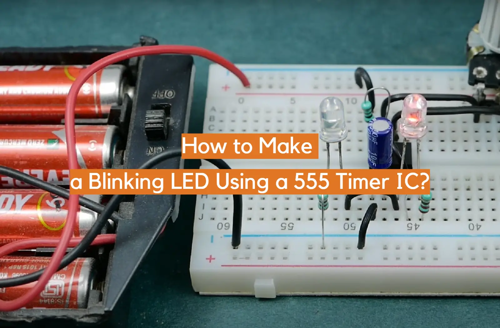
Interested in learning how to make a blinking LED? This guide will show you how to do it with a 555 timer IC. Blinking LEDs are a great way to learn about electronics, and they can also be used in fun projects like holiday displays or costumes. In this article, we’ll answer some common questions about making blinking LEDs and provide some tips for getting the best results. Let’s get started!
What is a 555 Timer IC
The 555 timer IC became extremely popular due to its low price and versatility; it has been called “the chip that changed the world” for this reason.
The 555 timer consists of two main parts: an analog comparator and a flip-flop. The comparator detects changes in voltage and sends signals to the flip-flop which then produces output pulses based on those signals. By adjusting the external resistors, users can control how long each output pulse lasts.
The 555 timer can be used for many different applications such as timers, pulse-width modulators, alarms, and oscillators. It is often used to generate short pulses that control other electronic components such as transistors and relays. In addition, the 555 timer can be used in conjunction with analog circuits to create accurate clocks and timing devices. [1], [2], [3]
Pinout of the 555 Timer
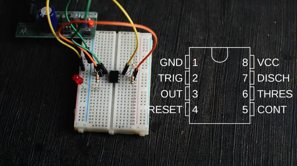
The 555 timer IC has 8 pins, labeled 1 through 8.
Pin 1 is the ground pin and must be connected to a negative voltage source in order for the timer to operate properly. Pin 2 is a Trigger pin which is used to set the timing cycle. It also helps to convert the state of flip-flops from the set (1) to reset (0).
Pin 3 is an Output pin which produces a pulse when the timer has completed its cycle. Pin 4 is a Reset pin and can be used to reset the timer after it has been triggered.
Pin 5 is a Control Voltage pin which can be connected to a voltage source in order to adjust the timing cycle of the 555 timer. Pin 6 is a threshold pin which monitors the input voltage in order to detect when it has gone above or below a certain level.
Pin 7 is a Discharge pin which controls the rate at which current flows from the capacitor. And finally, Pin 8 is a Supply Terminal which provides power to the timer IC. [2], [3]
Features of the 555 Timer
The 555 timer has a few features that make it ideal for use in blinking LED projects.
It can operate from a wide range of power supplies
The 555 timer can operate from a wide range of power supplies of different voltages and currents. This makes it easy to use in projects that require a variety of power sources, such as battery-powered circuits.
The maximum power dissipation per package is 600 mW
The maximum power dissipation per package is 600 mW, which makes it suitable for a wide range of applications. It can be used to drive high-power LEDs or even small motors and solenoids with ease.
It has an adjustable duty cycle of the timer
The 555 timer can be adjusted to have an adjustable duty cycle, meaning that you can control how long each output pulse will last. By adjusting the frequency of the signal input and the value of three external resistors, users can create pulses that are as short as nanoseconds or as long as hours. This makes it easy to adjust the blinking rate of an LED in a project. [2], [3]
Uses of Blinking LED Project
Making a blinking LED project is an excellent way to get started with basic electronics and understand how various components interact with each other. It requires minimal wiring, it’s easy to construct, and it can be used for a variety of applications. Here are just some of the uses where this project can come in handy:
- Light shows: You can use your blinking LED project to create stunning light show displays. This could be as simple as making a few LEDs blink alternately or something more complex like creating patterns that move across multiple LEDs.
- Visual warnings: Blinking LEDs can also be used to give visual warnings or alerts such as when there is smoke or fire detected in the vicinity, when there is a high level of pollution, or even to signal the presence of an intruder.
- Indicators: Blinking LEDs are also used as indicators in various electronics devices such as computers and phones. A blinking LED light can indicate that the device is running, that it is charging, or that it has been disconnected from a power source.
Now, to actually assemble the blinking LED project, you’ll need to obtain a few components. These include: a 555 timer IC, a breadboard, 9v Battery, battery clip, jump wires, capacitor 1μF, two 1k Ohm resistors (brown, black, red), 470k Ohm resistor (yellow, purple, yellow), and LED. [1], [2]
Connect it All Up
Once you have all the components, it is time to connect them up. To make the job easier, utilize the breadboard as it can make the wiring much simpler.
First of all, you need to place the 555 timer chip in the middle of the breadboard. It’s crucial to ensure you pull it in the right direction. If you fail to do so, the chip will burn upon the connection of the battery.
Now take a short jump wire to connect Pin 1 with the bottom row of the breadboard. This is the negative terminal of your battery and needs to be connected with ground. Similarly, you will need to connect the Pin 8 with the top row of the breadboard. This is the positive terminal.
Next, take another wire and connect Pin 4 of the terminal to Pin 8 of the terminal.
Following that, connect one end of the resistor to Pin 2 and the other end to the ground row. Similarly, connect another resistor between Pin 6 and ground.
Now, you will need to identify the legs of the first capacitor. It will have one short leg and one longer leg. The longer leg is a positive terminal while the shorter one is a negative terminal. Connect the positive leg to Pin 2 and the negative leg to the ground (GND). Next, connect Pin 2 with Pin 6 using yet another jump wire.
Next, it’s time to connect the resistors. You can connect these either way, so make sure you connect them with the correct side. Finally, connect Pin 6 and Pin using the 470k Ohm resistor.
Next, take the 1k Ohm (R2) resistor and connect Pin 7 to VCC. This will be the power source for your LED. Now, connect one end of the second 1k Ohm (R3) resistor with Pin 3 (output) and any empty row on the breadboard. This resistor will be connected to LED.
Before doing so however, you will need to identify the legs of the LED. Again, the shorter one is the negative terminal and the longer one is positive. Connect the long leg with the resistor and the short leg to the GND.
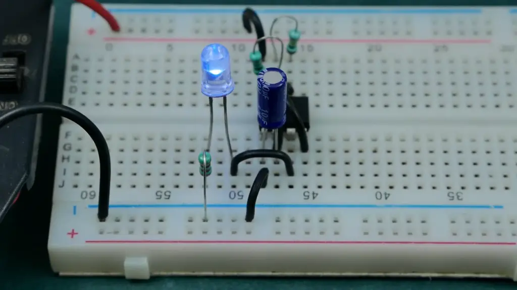
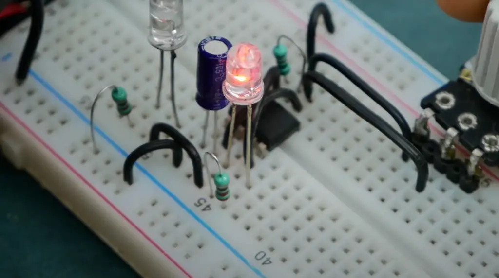
Finally, connect the battery clip to the 9V battery and place it on the back of the breadboard. You will see that your LED starts blinking as soon as you power up your circuit.
If everything has been connected correctly, your circuit should now be ready for testing. It will take some trial-and-error before you get it exactly right, but if done correctly, you will see a bright LED light blink at regular intervals.
Congratulations! Now you have successfully built a blinking LED using a 555 timer IC. With this project under your belt, you are now one step closer to becoming an electronics guru! Enjoy! [1], [2]
FAQ
How many pins does a 555 timer have?
The 555 timer is an integrated circuit with eight pins. Pin 1 is the ground, Pin 2 is the trigger, and Pin 3 is the output. Pin 4 is the reset, Pin 5 is the control voltage, Pin 6 is the threshold, Pin 7 is the discharge, and Pin 8 is the supply terminal. The trigger pin is an active low trigger, which starts the timer when it falls below one-third of the supply voltage. The output pin is where the output of the timer is available, and the load can be connected between Pin 3 and either Pin 1 or Pin 8. The reset pin sets the timer reading back to zero, and the control voltage pin modulates the output waveform. The threshold pin compares the applied voltage with the reference voltage and determines the input state of the flip-flop. The discharge pin is connected internally to the collector of the BJT, and the supply terminal is where all voltage sources are connected.
What are the advantages of using a 555 timer compared to other methods?
Using a 555 timer has several advantages over other methods for making a blinking LED. The most notable benefit is the low cost and ease of use when compared to microcontrollers or discrete logic. In addition, the 555 timer offers more flexibility in terms of frequency range, duty cycle control, and potential output waveforms. As well as being able to switch a wide variety of loads including LEDs, relays and motors, it also includes both active-low and active-high outputs which allows it to be used with both AC and DC circuits. This makes it an ideal choice for many different projects where pulsing an LED or controlling power is needed.
What is a 555 timer?
It can be used to produce square wave output signals in applications such as clocking digital circuits. The 555 timer is also commonly used to create pulse-width modulation (PWM) signals for use in controlling speed or brightness of devices such as motors and LEDs.
How do I make my LED IC 555 blink?
Making a blinking LED using the 555 timer IC is relatively simple and straightforward. To begin, you need to obtain a 555 timer IC, a 9V battery and battery clip, jump wires, a 1μF capacitor, one 470k Ohm resistor (colored yellow, purple, and yellow), two 1k Ohm resistors (colored brown, black, and red), and an LED.
First position the chip at the center of a breadboard and ensure that it is properly aligned to prevent any harm. Then, employ a short jump wire to link Pin 1 to the bottom row of the breadboard (ground), and another jump wire to link Pin 8 to the top row (VCC). Next, use a third jump wire to join Pin 4 to Pin 8.
Attach the positive terminal of capacitor C1 to Pin 2 and the negative terminal to the ground. Further, connect Pin 2 to Pin 6 with another jump wire. Connect Pin 6 to Pin 7 with a 470k Ohm resistor and Pin 7 to VCC with a 1k Ohm resistor. Link Pin 3 to an unoccupied row on the breadboard through a second 1k Ohm resistor, which will ultimately be linked to an LED in the following step. Lastly, connect the positive end of the LED to the resistor and its negative end to the ground.
To finish the circuit, connect the red wire of the battery clip to VCC and the black wire to the ground. Attach a 9V battery, and watch your circuit spring to life!
How to make a blinking LED circuit?
Making a blinking LED circuit with a 555 timer IC (integrated circuit) is an easy and fun project to do. The 555 timer IC is a highly versatile chip that can be used in many different applications, but it’s most commonly used for creating oscillators. An oscillator is basically an electrical circuit that produces regular repeating pulses or signals.
To build the blinking LED project, you will need to gather several components, including a breadboard, a 555 timer IC, a 9V battery and battery clip, jump wires, a 1μF capacitor, one 470k Ohm resistor (colored yellow, purple, and yellow), two 1k Ohm resistors (colored brown, black, and red), and an LED.
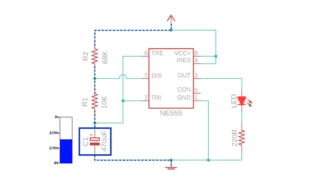
You will need to begin by placing the components on your breadboard and properly connecting them as per the circuit diagram. The 555 timer IC has 8 pins, which must be correctly inserted into your breadboard. Make sure to check the datasheet for a detailed description of each pin and its function.
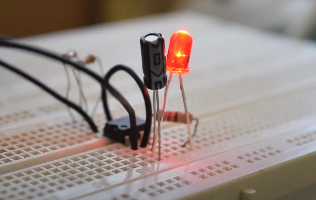
Once you’ve set up the components on your breadboard and properly connected them, you can connect a 9V battery to the battery clip and turn it on. Your LED should now start blinking! This is because of the constant flow of current created by the timing capacitor, which alternately charges and discharges through the resistors, switching off and on at regular intervals.
How does a blinking LED circuit work?
A blinking LED circuit is a simple electronic project that uses a 555 timer IC chip to control the flashing rate of an LED. The 555 timer acts as an oscillator, meaning it switches between charging and discharging its internal capacitor at regular intervals determined by the resistors and capacitors connected to it. When it reaches the voltage threshold (set by those same resistors & capacitors) the output pin on the 555 connects to ground, turning on your LED. When the voltage drops below this threshold, the output pin disconnects from ground and your LED turns off. This oscillation continues rapidly, causing your LED to blink at regular intervals depending on how you have set up your components.
How do you make an LED blink with a capacitor?
To create a circuit using a 555 Timer chip, start by placing it in the center of a breadboard. Make sure it is oriented correctly to avoid damage. Next, connect Pin 1 to the bottom row of the breadboard (ground) using a short jump wire. Connect Pin 8 to the top row (VCC) using another jump wire. Then, connect Pin 4 to Pin 8 using a third jump wire. Connect the positive leg of capacitor C1 to Pin 2 and the negative leg to the ground. Connect Pin 2 to Pin 6 using another jump wire.
Connect Pin 6 to Pin 7 using a 470k Ohm resistor, and Pin 7 to VCC using a 1k Ohm resistor. Connect Pin 3 to an empty row on the breadboard using a second 1k Ohm resistor, which will be connected to an LED in the next step. Finally, connect the LED’s positive leg to the resistor and its negative leg to the ground.
To complete the circuit, connect the red lead of the battery clip to VCC and the black lead to ground. Connect a 9V battery and watch your circuit come to life!
Useful Video: Adjustable Flashing/Blinking LED circuit on Breadboard | 555 Timer Project #5
Conclusion
A 555 Timer IC is a versatile and easy-to-use device, allowing users to create bold designs with a simple blinking LED. By understanding how the 555 Timer IC works, how it is configured, and what components are necessary for controlling the LED, any novice or expert user can successfully construct a blinking LED circuit.
The steps for constructing this circuit are relatively straightforward, but require careful consideration of the design parameters as well as appropriate soldering techniques in order to ensure successful operation and prevent short circuits. With patience and practice, anyone can create their own personalized blinking LED using a 555 timer IC.
By following this guide, you should now have a better understanding of how to make a blinking LED using a 555 timer IC. Once set up properly, a blinking LED can be used to spice up any project. It’s an easy and fun way to learn more about LEDs, 555 timer ICs, and circuit design in general. Good luck and have fun!
References
- https://www.instructables.com/Flashing-LED-using-555-Timer/
- https://www.elprocus.com/blinking-led-using-555-timer-ic/
- https://www.javatpoint.com/555-timers-ic