Within the IPC system, electronics are classified under Class 1, which is further subdivided into subclasses 2 and 3. Understanding the IPC class definitions for Class 1, 2, and 3 electronics is essential for anyone involved in the electronics industry or patent law [1].
In addition, understanding the IPC class definitions can also be useful for companies involved in the development and manufacturing of electronic devices. By knowing which IPC classes and subclasses their products fall under, companies can better understand the competitive landscape and potential patent infringement risks in their industry.
Overall, a clear understanding of the IPC class definitions for Class 1, 2, and 3 electronics is essential for anyone involved in the electronics industry, patent law, or related fields.
What Is IPC Class?
The IPC system was developed by the World Intellectual Property Organization (WIPO) and is used by patent offices around the world to categorize inventions according to their technical fields [2].
The IPC system is organized hierarchically, with the most general categories at the top and increasingly specific subcategories at the bottom. Each IPC class is represented by a letter, and each subclass is represented by a combination of letters and numbers. The IPC system covers a broad range of technologies, including electronics, mechanics, chemistry, and biotechnology, among others.
IPC classes are used to help patent examiners search for prior art that may be relevant to a patent application and to determine the scope of a patent. When filing a patent application, it is important to choose the appropriate IPC class and subclass to ensure that the patent is properly categorized and accurately reflects the technical field of the invention.
Class 1 electronics covers a broad range of electrical and electronic devices and systems, including computers, telecommunications equipment, audio and video equipment, and electronic components such as resistors and capacitors. Subclass 2 of Class 1 covers electronic devices that perform signal processing and computing functions, such as digital signal processors and microprocessors. Subclass 3 of Class 1 covers electronic devices used in the transmission and reception of signals, such as radio and television broadcasting equipment and telecommunications equipment.
IPC class definitions are used to determine the scope of a patent application and to help patent examiners search for prior art that may be relevant to the patent application. This makes it important for inventors and patent attorneys to understand the IPC class definitions and to choose the appropriate class and subclass for their patent applications.
Why Do IPC Standards Matter
Improved Product Quality and Reliability
IPC standards play a crucial role in ensuring the quality and reliability of electronic components and assemblies. They provide a framework for design, testing, and acceptance criteria for various components, including printed circuit boards (PCBs), cables, and connectors. Adherence to IPC standards helps manufacturers to minimize defects, reduce rework, and ensure consistent product quality.
IPC standards cover a wide range of aspects, from design and layout to material selection and testing.
For example, IPC-A-600 sets the standard for PCB fabrication, including the inspection criteria for bare boards. IPC-A-610 sets the standard for acceptance criteria for electronic assemblies, including solder joint acceptance criteria, cleanliness requirements, and other criteria for electronic assemblies. IPC-2221 provides guidelines for PCB design, including design rules for trace width, spacing, and hole size.
These standards help manufacturers to achieve consistent product quality and reliability by providing clear specifications and acceptance criteria for various components and assemblies [3].
Improved Communication
IPC standards also improve communication among manufacturers, suppliers, and customers by providing a common language and framework for discussing design and production requirements. Standardized terminology and specifications make it easier for everyone involved in the process to communicate effectively and ensure that the final product meets the required specifications.
For example, IPC-2581 is a standard for the exchange of data between PCB design and manufacturing processes. It defines a common data format for exchanging PCB design data and manufacturing information, making it easier for designers to communicate their requirements to manufacturers and ensure that the final product meets the desired specifications.
Reduced Costs
IPC standards can also help reduce costs by minimizing defects, reducing rework, and improving production efficiency. Adherence to IPC standards helps manufacturers to avoid costly mistakes and rework by providing clear guidelines for design, testing, and acceptance criteria. IPC standards also promote efficiency by providing guidelines for material selection, process optimization, and waste reduction.
For example, IPC-4101 provides specifications for base materials used in PCB fabrication, including requirements for material properties, thickness, and tolerance. By providing clear specifications for material selection, IPC-4101 helps manufacturers to choose the most appropriate material for their application and avoid costly mistakes. Similarly, IPC-7711/21 provides guidelines for the rework and repair of electronic assemblies, helping manufacturers to reduce waste and minimize the need for costly rework.
Improved Reputation and New Opportunities
Adherence to IPC standards can also enhance a manufacturer’s reputation and create new business opportunities. IPC standards have become a benchmark for quality and reliability in the electronics industry, and companies that adhere to these standards can demonstrate their commitment to producing high-quality products. This can lead to increased customer trust, better business relationships, and new opportunities for growth and expansion [4].
For example, many companies require their suppliers to adhere to IPC standards as a condition of doing business. By adhering to these standards, manufacturers can demonstrate their commitment to quality and reliability and gain a competitive advantage over companies that do not adhere to these standards. Additionally, IPC certification programs, such as the IPC-A-610 Certified IPC Trainer (CIT) program, can provide manufacturers with a competitive edge by demonstrating their expertise and commitment to quality.
IPC Category Definition
Class 1 – General Electronic Products
Class 1 generally refers to electronic products used in consumer and commercial applications. These products may include but are not limited to home appliances, televisions, audio/visual equipment, computers and peripherals, communications systems, security systems, and related components. These items must be reliable for use in the intended environment.
Class 2 – Dedicated Service Electronic Products
Class 2 generally refers to electronic products that have a dedicated or specific purpose such as those found in military/aerospace environments, medical facilities, industrial control systems, and process automation. These products must be able to function properly and consistently for extended periods of time with minimal maintenance or service requirements. Examples of Class 2 products include circuit boards or assemblies used in aerospace avionics, medical imaging systems, robotics, and industrial process control equipment [5].
Class 3 – High-Performance Electronic Products
Class 3 generally refers to products that have superior performance requirements such as high bandwidth, speed, or accuracy. These products are typically used in mission-critical applications where precision and reliability are essential. Examples of Class 3 products include those found in automotive safety systems, advanced navigation systems, military/aerospace communication networks, research and development projects, and other highly specialized areas. All components used for these items must be able to withstand the rigors of their intended environment without fail.
IPC 6012 3 / A-Level – Advanced Electronic Products
The IPC 6012/A-Level is the most stringent of all classifications and refers to products that must operate flawlessly in extremely harsh environments such as radiation, extreme temperatures, and other unexpected conditions. Examples of Class 3/A-Level products include those used in space exploration projects, medical imaging systems, military communication networks, and high-end industrial control systems. All components used must meet exceptionally high standards and be able to withstand prolonged exposure to these environments. This ensures that the product will perform properly even when unexpectedly exposed to extreme conditions [6].
Advantages of Type 2 PCB Production
Design Aspect
One significant advantage of Type 2 PCB production is that it allows for more design flexibility. In Type 2 production, components can be placed on both sides of the board, allowing for more space for connections, signal routing, and other design considerations. This flexibility can be especially useful for complex circuits or systems where space is limited. Additionally, Type 2 PCBs can support multiple layers, providing even more design options.
Manufacturing Aspect
Type 2 PCB production also offers advantages in terms of manufacturing. With components on both sides of the board, the board can be made smaller, which reduces manufacturing costs. Smaller boards also require fewer raw materials, reducing material waste and saving money. Furthermore, the use of smaller boards can lead to more efficient assembly processes, which can ultimately reduce production time.
Inspection Aspect
In terms of inspection, Type 2 PCBs can be easier to inspect and repair than other types of PCBs. With components on both sides of the board, it’s easier to access components for inspection and repair. This can be especially important for larger or more complex boards where components may be difficult to access. Additionally, with more space for routing and connections, it’s easier to avoid signal interference and other issues that can impact the reliability of the final product.
Advantages of Type 3 PCB Manufacturing
Design Aspect
One significant advantage of Type 3 PCB manufacturing is that it allows for more design flexibility. Type 3 PCBs support multiple layers, providing more space for connections, signal routing, and other design considerations. With the additional space, designers can incorporate more components, increasing the functionality of the PCB. Additionally, the additional layers provide greater flexibility in designing complex circuits and systems. Type 3 PCBs can also support blind and buried vias, which allow for more complex and compact board designs.
Manufacturing Aspects
Type 3 PCB manufacturing also offers advantages in terms of manufacturing. With multiple layers and complex designs, Type 3 PCBs require more precise manufacturing processes. However, the high level of precision results in more reliable and durable PCBs. The use of advanced manufacturing processes, such as laser drilling and high-resolution imaging, allows for tighter tolerances and finer features, making Type 3 PCBs ideal for high-performance applications.
Inspection Aspect
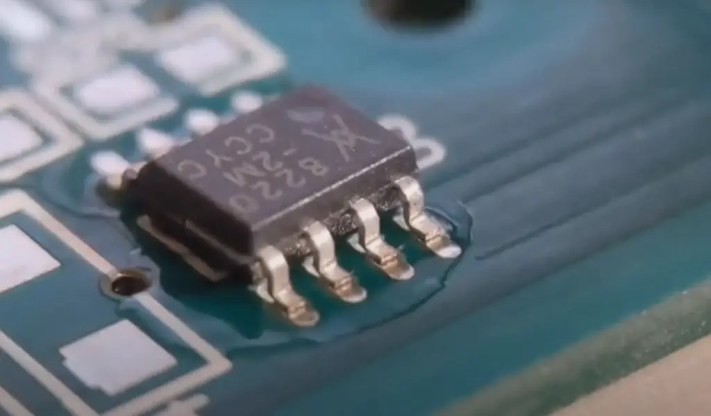
In terms of inspection, Type 3 PCBs can be more challenging to inspect than other types of PCBs due to their complexity. However, the use of advanced manufacturing processes and design techniques can make inspection easier. Additionally, with the use of advanced inspection techniques such as X-ray inspection, it is possible to verify that the board meets the required standards.
General Distinctions Between IPC Class 2 and Class 3
IPC Class 2 and 3 electronics are both considered to be high-reliability products, but there are some key differences between them.
Class 2 electronics are designed for use in applications that require higher levels of performance than what is provided by commercial-grade components. They typically have a longer operational life expectancy and can be used in extreme environmental conditions such as temperature fluctuations, vibration, shock, and humidity.
Class 3 electronics are built to the highest reliability standards available for the production of electronic components. This includes increased testing and screening during the manufacturing process as well as greater design complexity to ensure long-term operation with little or no downtime. These products often require more stringent assembly requirements than other classes of electronics due to their high level of complexity.
In general, Class 3 electronics are more expensive than their Class 2 counterparts due to the increased level of testing and screening involved in the production process. Additionally, they are used in applications where failure is not an option and reliability is paramount. Examples of these types of applications include military and aerospace applications, medical devices, automotive systems, and critical infrastructure systems.
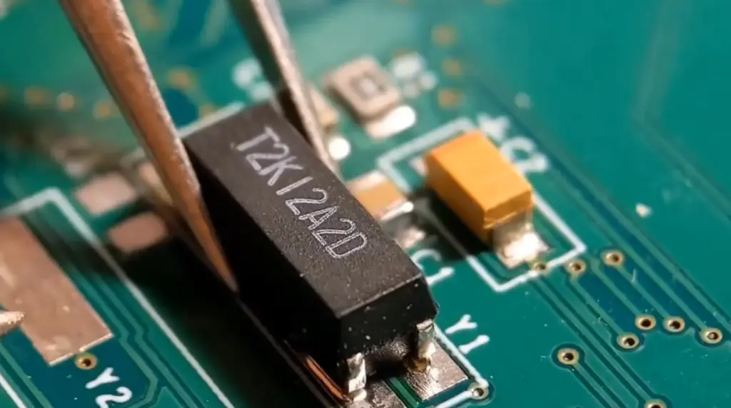
What Is The Difference Between Assembling Class 2 And Class 3
The Cleanliness And Installation Components Are Different
The main difference between assembling Class 2 and Class 3 Electronics is the cleanliness and installation of components. The IPC (Institute for Printed Circuits) standards require higher levels of cleanliness when assembling Class 3 than when assembling Class 2. This includes working in a “clean room environment”, using anti-static equipment, and wearing protective clothing while working.
Class 3 Assembly Is More Refined Than Class 2
Class 3 Electronics is also more refined than Class 2. The components used to assemble Class 3 Electronics must meet higher standards in terms of their size and the quality of the connections between them. Class 3 assemblies require more precise soldering techniques, as well as additional testing to ensure all components are working properly.
The Quality Level Is Higher For Class 3 Assemblies
Due to the stricter standards for cleanliness and component installation, the quality level of a Class 3 Electronic assembly is much higher than that of a Class 2 assembly. This ensures that any issues associated with incorrect connections or contamination will be addressed before they cause problems with performance or reliability down the line. In turn, this helps reduce manufacturing costs and increases the lifetime of the device.
Class 2 And Class 3 Electronics Are Used Differently
Though they have many differences, both Class 2 and Class 3 Electronics can be used for a variety of applications. Generally, Class 2 assemblies are best suited for products that require less precise components or are not expected to last long-term. On the other hand, Class 3 assemblies are ideal for products that require more reliable performance over a longer period of time [7].
The Difference In The Barrel Fill Levels
One final difference between Class 2 and Class 3 Electronics assemblies is the barrel fill levels. The barrel fill level of a component refers to how much of its available space is filled with solder. For Class 2 components, the standard barrel fill requirements are lower than those for Class 3 components. This means that fewer passes of soldering need to be completed in order to create an assembly.
Additionally, there are more specific requirements for component placement and soldering when working with Class 3 Electronics. For example, all leads must be securely connected to the board before any other operations are carried out, and all connections need to be inspected to ensure proper connection. Finally, all components must be tested after assembly to ensure they meet quality standards and function properly.
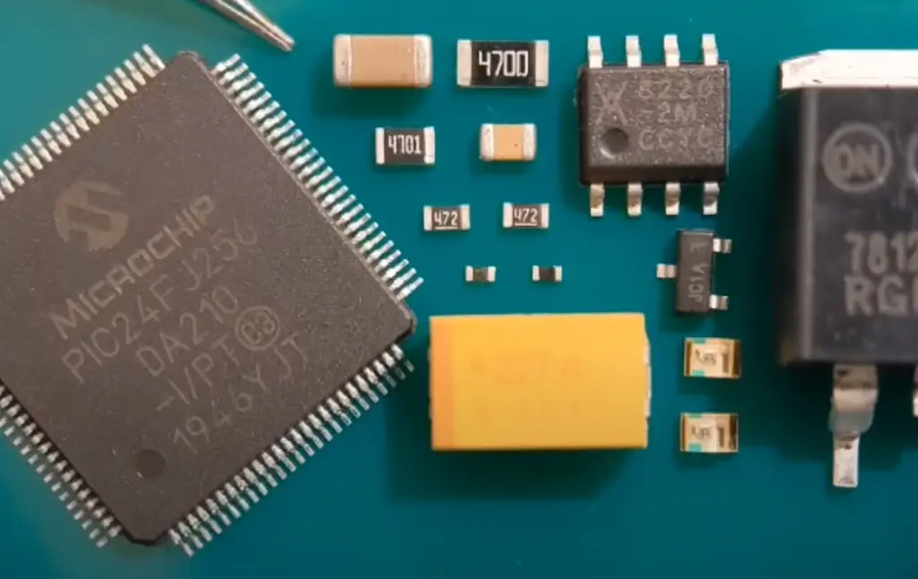
The Differences Between Class 2 and Class 3 for Printed Circuit Board Manufacturing
Annular Ring And Drill Breakout
One of the critical differences between Class 2 and Class 3 PCBs is the annular ring and drill breakout requirements. The annular ring is the copper pad that surrounds the drilled hole. In Class 2 PCBs, the annular ring requirements are less stringent than in Class 3 PCBs. This means that the minimum annular ring size is smaller for Class 2 PCBs, allowing for more flexible and cost-effective designs.
Drill breakout occurs when the drill bit exits the laminate, creating a breakout or a chipped edge around the hole. Class 3 PCBs have more stringent requirements for drill breakout than Class 2 PCBs, as the breakout can lead to a reduction in the integrity of the hole and damage to the board’s structural integrity.
IPC Annular Ring Acceptance Criteria
IPC standards define the acceptance criteria for annular ring sizes based on the size of the drill bit used. The minimum annular ring sizes for Class 2 and Class 3 PCBs vary, with Class 3 requiring a larger minimum annular ring size. For example, if a 0.8 mm drill bit is used, the minimum annular ring size for Class 2 is 0.2 mm, while for Class 3, it is 0.3 mm.
Design Rules Of Annular Rings
The design rules of annular rings include the minimum and maximum sizes, placement of pads, and clearance around the hole. The minimum and maximum sizes of the annular ring are determined by the drill bit size and the PCB class. The placement of pads determines the distance between the hole and the copper pad, while the clearance around the hole determines the space between the copper pad and the other traces.
IPC Class 2 Drill And Pad Diameter For 1/2 Oz Copper
IPC standards also define the drill and pad diameter requirements for PCBs with 1/2 oz copper thickness. For Class 2 PCBs, the minimum drill size is 0.25 mm, and the minimum pad diameter is 0.60 mm. The clearance between the drill and the copper pad should be at least 0.15 mm.
IPC Class 3 Drill & Pad Diameter For 1/2 Oz Copper
For Class 3 PCBs, the minimum drill size is 0.20 mm, and the minimum pad diameter is 0.50 mm. The clearance between the drill and the copper pad should be at least 0.10 mm. The smaller drill and pad sizes required for Class 3 PCBs increase their manufacturing complexity and cost.
PCB Dielectric Requirements
Another important factor to consider when comparing Class 2 and Class 3 PCBs is dielectric requirements. Dielectric materials are non-conductive materials that are used to separate the conductive layers of a PCB. The dielectric constant of a material is a measure of its ability to store electrical energy in an electric field. In general, Class 3 PCBs require a lower dielectric constant than Class 2 PCBs. This is because the use of high-frequency signals in Class 3 PCBs requires a higher level of signal integrity.
PCB Through-Hole Plating Requirements
Through-hole plating is a process of creating a conductive pathway between two or more layers of a PCB by electroplating copper onto the walls of a drilled hole. This is an important process for creating a reliable electrical connection between different layers of a PCB. However, the plating process can also introduce defects if not done correctly.
For Class 2 PCBs, the minimum plating thickness for a drilled hole is 0.025 mm. For Class 3 PCBs, the minimum plating thickness for a drilled hole is 0.020 mm. This thinner plating is necessary to allow for the smaller holes required in Class 3 PCBs.
Another important consideration for through-hole plating is the use of electroless nickel immersion gold (ENIG) plating.
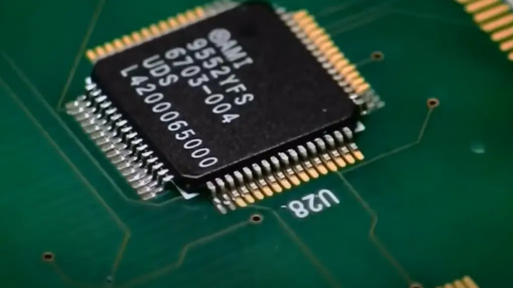
However, ENIG can also introduce defects such as voids, cracks, and poor adhesion if not done correctly. Therefore, it is important to ensure that the ENIG process is closely monitored and controlled for both Class 2 and Class 3 PCBs.
Examples of IPC Standards for Electronics
Class 1:
- Soldering and Assembly Processes (IPC-A-610);
- Printed Board Design (IPC-2221);
- Requirements for Printed Board Fabrication (IPC-6012);
Class 2:
- Discrete Wiring and Interconnecting Components (J-STD-);
- Rigid Flexible Circuitry Fabrication and Assembly (IPC/WHMA A620B);
Class 3:
- Surface Mount Design and Land Pattern Standard (IPC 7351B);
- Microvia Technology Design Guide (IPC 4761A);
These IPC standards provide guidance on the design, assembly, testing, and packaging of electronic assemblies. They are designed to help manufacturers produce products that meet the highest levels of quality and reliability. By adhering to these standards, manufacturers can ensure their products will meet customer expectations and industry regulations.
Additionally, many organizations require compliance with these guidelines in order to receive certification or approval for a product. It is important for any organization producing electronics to understand the requirements outlined by IPC standards in order to maintain the highest levels of quality and safety [8].
IPC Defects in PCB
Annular Ring
The annular ring is a critical feature of a PCB, as it provides a connection point between the component lead and the PCB pad. Annular rings are typically circular or oval in shape and are often found on through-hole components, which require a mechanical connection to the PCB. The annular ring’s size and shape are crucial for the component’s electrical and mechanical performance.
IPC standards specify the minimum and maximum sizes for the annular ring to ensure a reliable connection between the component and the PCB. If the annular ring is too small, it may not provide a secure mechanical connection, leading to a loose or broken component. If the annular ring is too large, it may short to adjacent traces or vias, leading to a failed device.
Annular ring defects can occur due to various reasons, including improper drill size, inadequate plating thickness, or inaccurate placement. Manufacturers and assemblers can prevent annular ring defects by using proper drill sizes, controlling the plating process, and ensuring accurate component placement.
Solder Joint
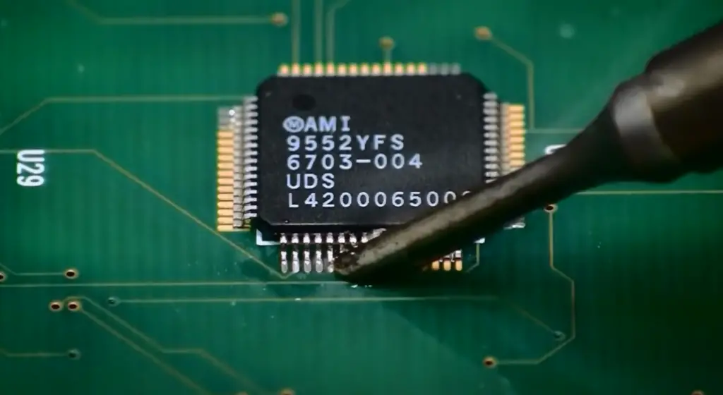
Solder joints are the connections between the component lead and the PCB pad and are critical for electrical and mechanical performance. Solder joints provide a stable mechanical connection while also ensuring proper electrical conductivity. Solder joints can be formed by various methods, including wave soldering, reflow soldering, and hand soldering.
IPC standards specify the minimum and maximum acceptable solder joint dimensions, including fillet size, height, and wetting. If the solder joint is too small, it may not provide a reliable connection, leading to a failed device. If the solder joint is too large, it may create a short circuit or damage the component.
Solder joint defects can occur due to various reasons, including improper solder paste application, incorrect temperature profile, and inadequate flux. Manufacturers and assemblers can prevent solder joint defects by using proper soldering techniques, controlling the temperature profile, and using high-quality flux.
Component Misalignment
Component misalignment occurs when the component is not placed correctly on the PCB pad. Misaligned components can result in poor electrical performance and a lack of mechanical stability. Component misalignment can occur due to various reasons, including improper pick and place equipment calibration, insufficient solder paste volume, or inaccurate machine vision systems.
IPC standards specify the maximum acceptable component misalignment, which varies depending on the component’s size and type. If the component misalignment is too great, it may lead to a failed device, as the component may not provide the necessary electrical or mechanical connection.
Manufacturers and assemblers can prevent component misalignment defects by using proper calibration techniques for picking and placing equipment, controlling solder paste volume, and ensuring accurate machine vision systems.
FAQ
1. What is the difference between IPC Class 1 and IPC Class 2?
IPC Class 1 and IPC Class 2 are both part of the International Patent Classification system for categorizing patents and patent applications based on technology areas. Class 1 encompasses a wide range of electrical and electronic devices and systems, while Class 2 specifically covers electronic devices that perform signal processing and computing functions.
In other words, Class 2 is a subset of Class 1 that focuses specifically on devices and systems that involve digital signal processing and computing functions. This distinction is important for patent examiners and inventors to ensure that their patent applications are properly categorized and classified within the IPC system [9].
2. What is IPC 6012 Type 3 Class 3?
IPC 6012 Type 3 Class 3 is a standard for printed circuit boards (PCBs) that specifies requirements for the design, materials, and construction of high-reliability PCBs used in aerospace, defense, and other high-performance applications. Type 3 refers to the highest level of performance and reliability, while Class 3 specifies the highest level of quality and workmanship for the production of PCBs.
3. What is IPC level 3?
IPC level 3 refers to the highest level of certification for individuals in the electronics industry who have demonstrated proficiency in the IPC-A-610 standard for the acceptability of electronic assemblies. IPC level 3 certified individuals are qualified to train and certify others in the standard, and are considered experts in the field.
4. What is IPC 610?
IPC 610 is a standard for the acceptability of electronic assemblies that outlines criteria for the quality and workmanship of electronic assemblies, including PCBs and other electronic components. The standard covers a wide range of requirements, including surface mount technology, through-hole technology, and cleanliness.
5. What is the difference between IPC 6012 Class 2 and IPC 600?
IPC 6012 Class 2 is a standard for high-reliability PCBs used in a variety of applications, while IPC 600 is a general specification for PCB design and manufacturing. IPC 6012 Class 2 includes specific requirements for the design, materials, and construction of high-reliability PCBs, while IPC 600 provides general guidelines for the overall design and manufacture of PCBs [10].
6. What is the difference between IPC 6012 and IPC 6013?
IPC 6012 and IPC 6013 are both standards for printed circuit boards, but they cover different types of PCBs. IPC 6012 specifies requirements for high-reliability PCBs used in a range of applications, while IPC 6013 covers flexible printed circuit boards (FPCBs).
7. What is IPC 6012 Class 2 thickness?
IPC 6012 Class 2 specifies minimum thickness requirements for the dielectric materials used in the construction of high-reliability PCBs. The minimum thickness for Class 2 PCBs is 0.0015 inches for single-sided and double-sided PCBs and 0.0025 inches for multilayer PCBs.
8. What is the difference between Class 2 and Class 3 circuits?
Class 2 and Class 3 circuits refer to different levels of electrical circuits as defined by the National Electric Code (NEC). Class 2 circuits are low-power circuits that operate at a maximum of 30 volts and 100 watts and are typically used for control and signal circuits. Class 3 circuits are higher-power circuits that operate at a maximum of 150 volts and 100 watts and are typically used for power-limited fire alarm systems and other safety applications.
9. What is Class 3 PCB?
Class 3 PCB is a term used to refer to printed circuit boards that meet the highest level of quality and reliability standards. These PCBs are typically used in high-reliability applications such as aerospace, defense, and medical equipment, where failure is not an option. Class 3 PCBs have the highest level of quality and workmanship requirements and are subject to rigorous testing and inspection procedures to ensure their reliability and performance.
10. What is Class 1 in electrical?
Class 1 is a designation used in electrical safety standards to indicate that an electrical device or equipment has an extra layer of protection against electrical shock. Class 1 devices have a protective ground wire that connects to the earth to prevent electrical shock in case of a fault or malfunction.
11. What is the difference between Class 1 and Class 2 and Class 3 power supply?
Class 1, Class 2, and Class 3 power supplies are defined by their safety requirements and maximum power output. Class 1 power supplies require a protective earth connection and have a maximum output power of 600 watts. Class 2 power supplies have no exposed metal parts and a maximum output power of 100 watts. Class 3 power supplies have a maximum output power of 60 watts and are typically used for low-voltage lighting applications [11].
12. What is the difference between a Class 1 and Class 2 electrical device?
A Class 1 electrical device has a protective earth connection and is designed to prevent electrical shock to the user. Class 2 electrical devices do not have a protective earth connection but have an additional layer of insulation to prevent electrical shock. Class 1 devices are typically used in higher-power applications, while Class 2 devices are used in low-power applications.
13. What is a Class I/II/III power supply?
Class I, Class II, and Class III power supplies are defined by their safety requirements and maximum output power. Class I power supplies require a protective earth connection and have a maximum output power of 600 watts. Class II power supplies have no exposed metal parts and a maximum output power of 100 watts. Class III power supplies have a maximum output power of 60 watts and are typically used for low-voltage lighting applications.
14. What is a Class 2 conductor?
A Class 2 conductor is a type of electrical wire that is rated for use in low-voltage applications. Class 2 conductors have a maximum voltage rating of 150 volts and are typically used in control and signal circuits.
15. What is the tolerance for IPC Class 2?
The tolerance for IPC Class 2 refers to the allowable variation in dimensions and other characteristics of printed circuit boards (PCBs) that meet the Class 2 standard. The specific tolerance requirements vary depending on the type and function of the PCB.
16. What is IPC-a-610 and IPC J-STD-001?
IPC-A-610 and IPC J-STD-001 are both standards for the acceptability of electronic assemblies. IPC-A-610 outlines criteria for the quality and workmanship of electronic assemblies, including PCBs and other electronic components. IPC J-STD-001 covers requirements for soldered electrical and electronic assemblies.
17. What is the IPC 9592B rule?
IPC 9592B is a standard for the design and manufacture of power conversion devices used in aerospace and defense applications. The standard covers requirements for the design, testing, and inspection of power conversion devices to ensure their reliability and performance in extreme environments. It includes specifications for materials, environmental testing, and other key factors that affect the reliability and performance of power conversion devices.
18. What are the IPC spacing rules?
IPC spacing rules refer to guidelines for the minimum distance between components and conductors on a printed circuit board (PCB) to prevent electrical interference and ensure proper functionality. These rules are defined in the IPC-2221 standard, which specifies spacing requirements based on the voltage, current, and frequency of the circuits on the PCB [12].
19. What is IPC J STD 001 Class 3?
IPC J-STD-001 Class 3 is a certification level for the manufacturing and assembly of high-reliability electronic products. This certification ensures that the products meet the highest level of quality and reliability standards, and are suitable for use in critical applications such as aerospace, defense, and medical equipment. Class 3 certification requires the use of the most stringent manufacturing and assembly processes, and requires rigorous testing and inspection procedures.
20. What is IPC 7093?
IPC 7093 is a standard for the design and manufacture of printed circuit boards (PCBs) used in automotive applications. The standard covers requirements for the design, materials, and manufacturing processes used in automotive PCBs, and includes guidelines for testing and inspection to ensure the reliability and performance of these PCBs.
21. What is IPC a620?
IPC A-620 is a standard for the acceptability of cable and wire harness assemblies. The standard covers requirements for the design, materials, and manufacturing processes used in cable and wire harness assemblies, and includes guidelines for testing and inspection to ensure the reliability and performance of these assemblies.
22. What is the aspect ratio of IPC Class 3?
The aspect ratio of IPC Class 3 refers to the ratio of the thickness of a printed circuit board (PCB) to the diameter of the smallest drilled hole on the board. The aspect ratio for Class 3 PCBs is typically 8:1 or higher, which means that the thickness of the PCB is eight times the diameter of the smallest drilled hole.
23. Are laptops Class 1 or 2?
Laptops are typically Class 1 electrical devices, as they are designed to operate at higher power levels and have a protective earth connection to prevent electrical shock to the user. However, the specific classification of a laptop may vary depending on the manufacturer and the country of use.
24. How do I know if my appliance is Class 1 or Class 2?
Class 1 appliances will have a protective earth connection, while Class 2 appliances will have an additional layer of insulation to prevent electrical shock [13].
25. What is a Class 2 power supply?
Class 2 power supplies are electrical power supplies that are designed to provide low-voltage power to electronic devices. These power supplies have no exposed metal parts and are designed to prevent electrical shock to the user. Class 2 power supplies have a maximum output power of 100 watts and are typically used in low-power applications.
Useful Video: What are IPC standards for PCB Design PCB Fabrication and PCB Assembly
References
- https://blog.matric.com/ipc-class-definitions-class-1-2-3-electronics
- https://www.protoexpress.com/blog/ipc-class-2-vs-class-3-different-design-rules/
- https://www.raypcb.com/pcb-ipc-standards/
- https://tempoautomation.com/blog/how-does-the-ipc-classification-impact-pcb-manufacturing/
- https://henwaytech.com/whats-on-the-bench-blog/ipc-class-1-class-2-and-class-3-inspection-standards-in-pcb-assembly
- https://www.nextpcb.com/blog/ipc-class-2-vs-3-the-differences-in-pcb-ipc-standards
- https://www.pcb-hero.com/blogs/lilycolumn/ipc-class-2-vs-class-3
- https://www.ourpcb.com/ipc-class.html
- https://www.quick-pcba.com/pcb-news/ipc-standards-and-ipc-classes.html
- https://www.mclpcb.com/blog/ipc-standards-for-pcbs/
- https://www.pcbnet.com/blog/class-ii-vs-class-iii-inspection-standards-in-pcb-assembly/
- https://www.circuits-central.com/blog/ipc-class-2-vs-class-3-whats-the-difference/
- https://wellerpcb.com/the-difference-between-ipc-6012-ipc-a-600-and-ipc-a-610/





Leave a Reply