
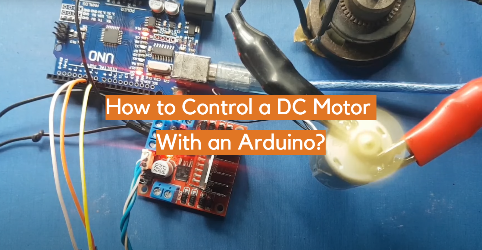
In this article, we will show you how to control a DC motor with an Arduino. This is a common task that many beginners struggle with, so we wanted to provide a comprehensive guide that will walk you through the process step-by-step. We will also answer some of the most common questions that people have about this topic. So if you’re ready to learn how to control a DC motor with an Arduino, then let’s get started!
Arduino and Its Benefits (detailed answer)
It consists of both a physical programmable circuit board (often referred to as a microcontroller) and a piece of software, or IDE (Integrated Development Environment), that runs on your computer. The board can be connected to a variety of inputs, including sensors, motors, lights, and sound cards.
One of the primary benefits of using Arduino is its simplicity. The boards are easy to use, with no need for complicated wiring or soldering – just plug it in and you’re ready to go! Additionally, the IDE has a user-friendly interface which makes programming the boards straightforward even for beginners. Furthermore, there are many online resources available such as tutorials, example code, and support forums that can help users get started quickly.
Another advantage of using Arduino is its flexibility; the boards are compatible with a wide range of sensors and devices which allows for a huge variety of projects to be built. Additionally, Arduino devices can communicate with other hardware platforms such as Raspberry Pi or BeagleBone Black. This makes them ideal for creating custom Internet-of-Things (IoT) applications.
Finally, Arduino is cost effective – the boards are relatively cheap and often include everything necessary to get started right away. This makes it an excellent choice for hobbyists who want to experiment without breaking their budget. Moreover, many parts and components used in Arduino projects are widely available and easy to find, allowing users to build more complex and sophisticated projects. [1]
Types of Motors (detailed answer)
One of the most popular projects for the Arduino platform is controlling motors. Motors are used in a wide variety of applications, from robotics and automated manufacturing to household appliances and toys. There are several different types of motors that can be controlled with an Arduino:
DC Motor
It is powered by direct current (DC) and is the most common type of motor used in Arduino projects. DC motors include various sub-types such as brushed and brushless, with the former being the most common.
Servo Motor
It consists of a small electric motor coupled to a gearbox which then drives a rotating shaft or armature. The control wire sends out a high-frequency pulse-width modulation (PWM) signal which tells the motor how far to rotate or move.
Servos are often used for robotics projects where precise movement is required. They are especially useful for applications involving pan/tilt mechanisms or any other application where precise movement is needed.
Stepper Motor
Steppers are commonly used for positioning equipment such as CNC machines, elevators, 3D printers, and automated manufacturing systems.
Stepper motors are ideal for projects where precise positioning is required. They can be controlled with a variety of interfaces including Arduino boards and even computers via USB. In addition, steppers require no feedback from the physical environment to work so they are often used in applications where speed or accuracy needs to remain constant regardless of external factors such as torque or load. [2]
DC Motor Installation (detailed answer)
Now that you know different types of motors and the application they can be used for, you need to know how to install one. Installing a DC motor with an Arduino is fairly straightforward and requires no complicated wiring or soldering. In this and following sections we will discuss how to install and connect a DC motor with an Arduino.
For this you will need several components:
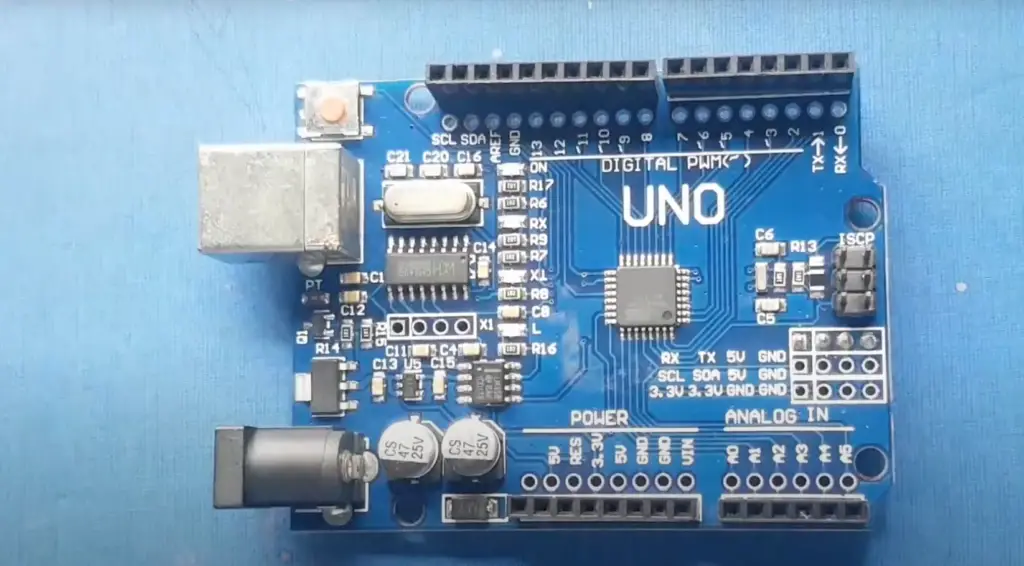
- 1x Arduino UNO board
- 1x PN2222 Transistor
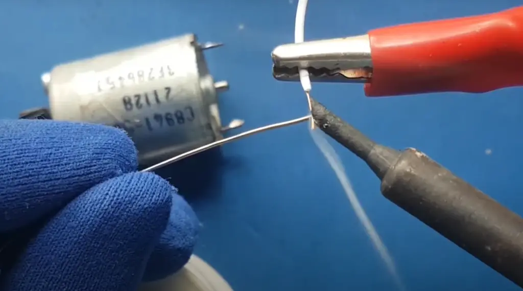
- 1x Small 6V DC Motor
- 1x 1N4001 diode
- 1x 270 Ω Resistor
Connecting DC Motor to Arduino (detailed answer)
Now let’s proceed with the procedure to connect the DC motor to the Arduino board.
First off, you need to connect the DC motor to Arduino. It should be connected to the 5V and ground pins. To do this you need a PN2222 transistor, a 1N4001 diode, and a 270 Ω resistor.
The PN2222 should be connected between pin 3 and the motor’s positive terminal.
The transistor especially should be wired correctly. The flat side of the transistor should be facing toward the Arduino board in order to follow this configuration. For optimal performance, the diode’s striped end should be pointed towards the +5V power line.
Now it’s time to enter the code that defines the pin mode and the motor speed.
int motorPin = 3;
void setup() {
}
void loop() {
digitalWrite(motorPin, HIGH);
}
Here, the motorPin is the pin where we have connected the motor. You can use any of the digital or analog pins depending on your setup.
It’s now time to make the code more advanced, first we will explain how to control the speed of the motor. This time, you will need to connect the motor through a resistor to the Pin 9.
int motorPin = 9;
void setup() {
pinMode(motorPin, OUTPUT);
Serial.begin(9600);
while (! Serial);
Serial.println(“Speed 0 to 255”);
}
void loop() {
if (Serial.available()) {
int speed = Serial.parseInt();
if (speed >= 0 && speed <= 255) {
analogWrite(motorPin, speed);
}
}
}
Here, we have used the Serial monitor to control the speed of the motor. You can now enter any value between 0 and 255 in order to control the speed of your DC motor. If you want to set a specific speed, enter that value in the serial monitor and click send. [3]
Controlling the Direction of DC Motor (detailed answer)
Now that we know how to control the speed of a DC motor using an Arduino, let’s move on to controlling the direction. This can be done by using a H-bridge circuit. H-bridges are used to control the direction of the motor and can be built using four transistors, relays or motor drivers like L298N.
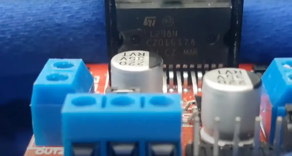
To guide you through this process, we will be utilizing the impressive and reliable L298 H-Bridge IC. This powerful device can help manage the velocity and route of both DC motors and stepper motors at once! It is capable of a current rate as high as 2A for every motor – but to guarantee optimal performance, heat sinks are an absolute must if you want to reach those currents.
For this you will need:
- L298 bridge IC
- DC motor
- Arduino UNO
- Breadboard
- Jumper wires
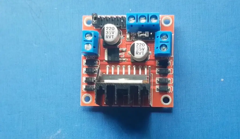
As you can see, this time we included a L298 bridge IC. This is a fundamental component when it comes to controlling the direction of your DC motor. Now, let’s get started and build the circuit!
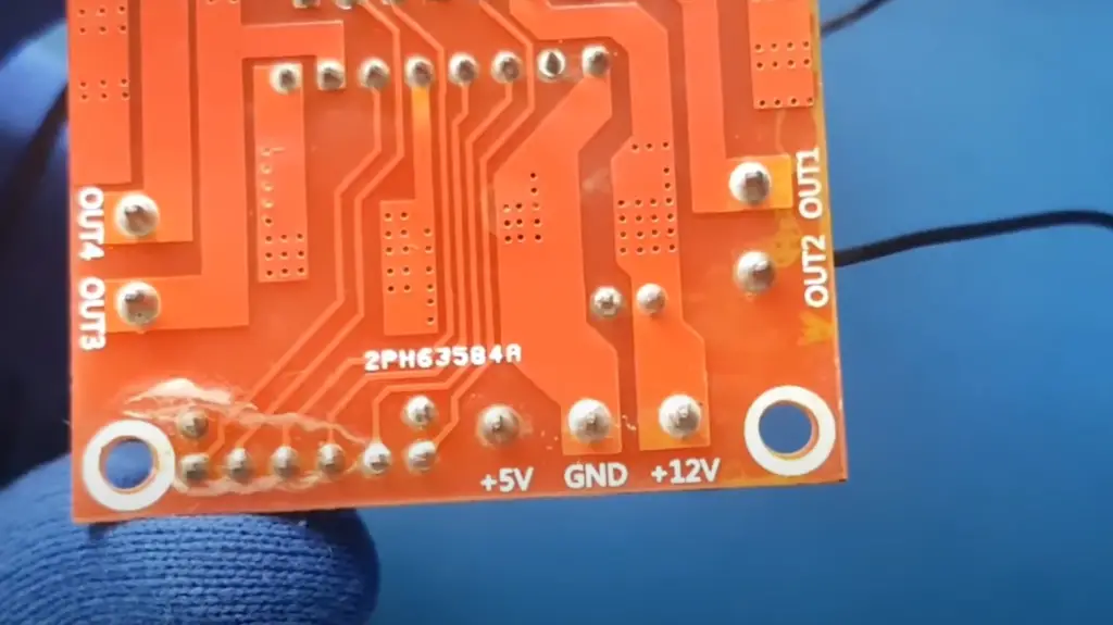
The L298 IC consists of two main parts; an input side and an output side. The input side is what will receive the signals from our Arduino board, while the output side will send electrical power to our DC motor.
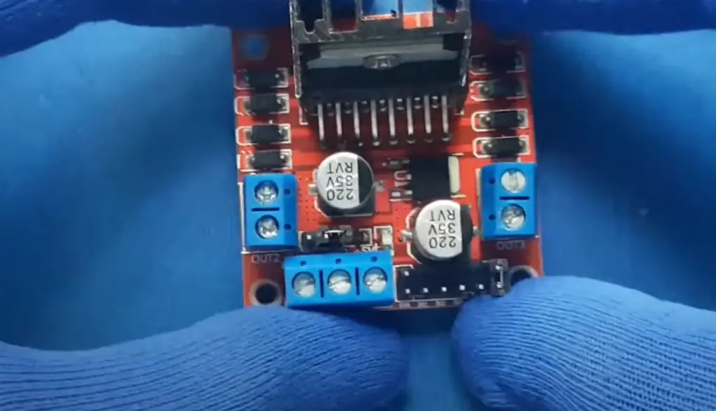
To control each motor, there are three input pins: IN1 and IN2 for Motor1 and Input3, Input4, and Enable2 for Motor2. Additionally, a separate Enable pin (EN) is necessary to activate the motors. For a single motor, we’ll link the Arduino to inputs IN1 (pin 5), IN2 (pin 7), and Enable1 (pin 6) of the L298 IC. Pins 5 and 7 will be digital on/off signals while pin 6 requires a pulse-width modulated signal for adjusting engine speed.
Pin IN1 of the IC L298 is connected to pin 8 of Arduino while IN2 is connected to pin 9. These two digital pins of the Arduino control the direction of the motor. The EN A pin of IC is connected to the PWM pin 2 of Arduino. This will control the speed of the motor.
To set the values of Arduino pins 8 and 9, we have used the digitalWrite() function, and to set the value of pin 2, we have to use the analogWrite() function. Securely attach the connecting pin of IC SENS to the ground. Next, link your Arduino board to a computer with an Arduino USB cable and upload the program through the Arduino IDE software. Finally, provide power to the Arduino board using power supply, battery, or USB cable.
Now it’s time to code!
const int pwm = 2 ; //initializing pin 2 as pwm
const int in_1 = 8 ;
const int in_2 = 9 ;
//For providing logic to L298 IC to choose the direction of the DC motor
void setup() {
pinMode(pwm,OUTPUT) ; //we have to set PWM pin as output
pinMode(in_1,OUTPUT) ; //Logic pins are also set as output
pinMode(in_2,OUTPUT) ;
}
void loop() {
//For Clock wise motion , in_1 = High , in_2 = Low
digitalWrite(in_1,HIGH) ;
digitalWrite(in_2,LOW) ;
analogWrite(pwm,255) ;
/* setting pwm of the motor to 255 we can change the speed of rotation
by changing pwm input but we are only using arduino so we are using highest
value to driver the motor */
//Clockwise for 3 secs
delay(3000) ;
//For brake
digitalWrite(in_1,HIGH) ;
digitalWrite(in_2,HIGH) ;
delay(1000) ;
//For Anti Clock-wise motion – IN_1 = LOW , IN_2 = HIGH
digitalWrite(in_1,LOW) ;
digitalWrite(in_2,HIGH) ;
delay(3000) ;
//For brake
digitalWrite(in_1,HIGH) ;
digitalWrite(in_2,HIGH) ;
delay(1000) ;
}
This code will make the motor spin clockwise for 3 seconds, followed by a brake for 1 second and then anti-clockwise for 3 seconds.
We hope you found this tutorial useful and that you now have an understanding of how to control both the speed and direction of a DC motor with an Arduino! We wish you luck on your projects! [3]
Potential Projects That Utilize DC Motors (detailed answer)
So now that you know how to control DC motors with an Arduino, what kinds of projects can you create? Here are a few ideas to get your creative juices flowing:
Laser Rangefinder for Arduino (detailed answer)
An interesting project you can do with an Arduino and a DC motor is to create a laser rangefinder. This type of device works by measuring the time it takes for a laser beam to travel from its source, bounce off an object, and return back to the source. To build one of these devices, you’ll need:
- Arduino Nano R3
- OLED;
- Laser tape pressure;
- LM2596 DC module;
- Wires and headers for assembly
Lasers are becoming more and more popular in the security sector nowadays, and laser rangefinders are used in numerous applications such as navigation, surveillance and even measuring distances. So why don’t we make our own?
Arduino Robo Crane (detailed answer)
Robo Crane is a robot arm that uses an Arduino microcontroller to control a DC motor. This allows you to move the arm up and down with accuracy, as well as rotate it left and right. To control the Robot Crane using an Arduino, you’ll need to connect the Arduino board to the DC motor using cables and then program it using code.
This is an interesting project for anyone who is curious in trying out robotics. For this task you will need:
- MAX009
- Arduino UNO
- DC motor
- Ultrasonic sensor
- Infrared sensor.
Once you build your robot crane, you’ll be able to move it up and down, left and right, as well as pick up and drop off items!
Robot Car Project (detailed answer)
Another use of DC motors with Arduino is in a DIY Robot Car. This project requires you to construct and program a robotic car from the ground up. It involves connecting your DC motors to an Arduino, along with other electronic components such as photoresistors, servos, buttons etc.
For this project you will need a set of DC motors, a car (obviously!), a DC motor of 12 volts to operate, an Arduino board to control, jumper wires, and breadboards. Additionally, you will need to write a program for the Arduino that will allow your robot car to move around. You can use simple commands such as turn left/right and go forward/backward for basic navigation.
Once you have the basics working you can consider adding features like obstacle avoidance, line following or even machine learning capabilities! All these features are possible using an Arduino board and some programming knowledge.
Herb Box Eco System using Arduino (detailed answer)
A herb box is a great way to bring fresh herbs into your kitchen and enjoy the practicality of growing them yourself. By using an Arduino, you can create a simple herb box ecosystem that will automatically water and monitor your plants with minimal effort.
To get started, you will need some basic components including:
- Arduino UNO;
- Amazon Alexa;
- Light;
- Aqua pump;
- DC motor;
- Plant;
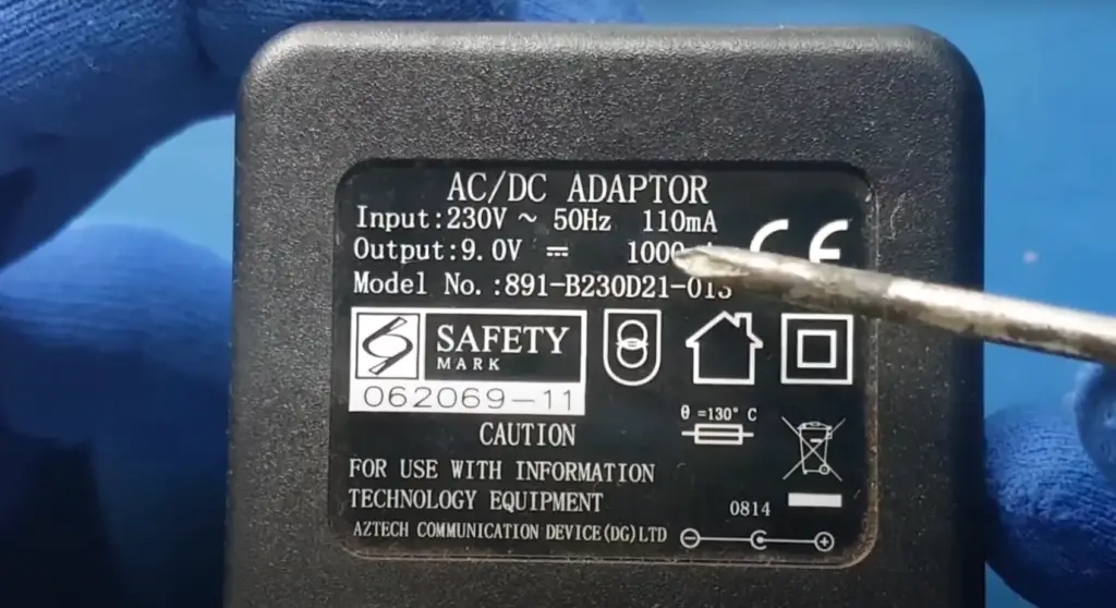
- Power adapter;
How this system works is simple. The Arduino UNO acts as the brain of this setup and is responsible for controlling various components such as the light, aqua pump, and DC motor. With the Amazon Alexa, you can control these components by voice commands.
For example, you could say “Alexa turn on the light” and it will automatically turn on your grow lights. This allows you to easily adjust the amount of light your plants receive during different times of day without having to manually adjust them yourself.
Automatic Plant Watering System using Arduino Uno (detailed answer)
If you’re really interested in gardening, you may be looking to take your home garden to the next level. In this guide, we’ll show you how to use an Arduino Uno and some basic components to build a fully-automated plant watering system.
An automated plant watering system offers many advantages over traditional methods of watering plants, including no more forgetting to check if they’ve been watered and no need for manual labor. It also gives you better control and consistency in your gardening efforts; with just a few simple modifications and adjustments, you can water different plants on different schedules or even automate the entire process so that it runs without any user input.
To get started, first gather all the necessary parts needed for your project:
- Arduino UNO;
- DC motor;
- Soil moisture sensor;
- Temperature sensor
One of the most common and useful ways to use a DC motor with Arduino is for an automatic plant watering system. With a few simple components, you can build your own DIY automatic plant watering system that will keep your plants happy and healthy! [4]
FAQ
What is a DC motor? (detailed answer)
This means it uses a DC voltage source, such as batteries or a regulated power supply, to turn on the motor. The stator and rotor of the motor contain permanent magnets which interact with each other to produce rotational motion.
The direction of rotation can be reversed by reversing the polarity of the applied voltage. This makes DC motors ideal for applications requiring one-way movement or reversible movement, such as robotic arms and robots.
DC motors are also used in many consumer products, such as fan controllers, power tools, household appliances, and more. They are commonly found in everyday items like toy cars and remote-controlled planes.
How to control the speed of a DC motor with Arduino and without potentiometers? (detailed answer)
Controlling the speed of a DC motor with Arduino and without potentiometers is possible using pulse-width modulation (PWM). In PWM, the average voltage applied to the motor is proportional to the duty cycle of a square waveform. By varying the duty cycle, you can vary the speed of your DC motor.
An Arduino can generate this square waveform by outputting a digital signal on one of its outputs. This output should be connected to the enable pin or base connection of an H-bridge circuit that controls your motor. To produce different speeds, you’ll need to vary the digital signal sent through this enable pin or base connection. This is done by sending digital “pulses” at certain frequencies. The frequency determines the speed of your motor.
Is it possible to control multiple DC motors with an Arduino? (detailed answer)
Yes, it is possible to control multiple DC motors with an Arduino. Using the same concepts discussed in this guide, you can use a combination of digital pins and transistors that are connected in parallel to create a circuit able to power multiple DC motors at once.
What can you do with DC motors? (detailed answer)
DC motors are some of the most versatile pieces of equipment in the world. They come in a wide variety of sizes and shapes, with different levels of power and speed capability. With an Arduino-controlled DC motor, you can control and automate a wide range of physical tasks such as robotic arms, automated vehicles, small wind turbines and even large industrial machines. DC motors can also be used to actuate valves or switches, move linear actuators, drive pumps and other machinery, etc.
The ability to precisely control the speed and torque output of a DC motor makes them ideal for many robotic applications. For example, if you want your robot arm to move slowly and accurately then using an Arduino-controlled DC motor is probably the way to go. Or if you need your robot to move quickly and powerfully, then a high-speed DC motor would be perfect for the job.
In addition to robotic applications, an Arduino-controlled DC motor can also be used in a wide range of other applications where precise speed control is important.
How to control DC motors using Arduino? (detailed answer)
Controlling DC motors with an Arduino is easy and straightforward. There are two main methods for controlling a DC motor with an Arduino: using a digital signal (PWM or Pulse Width Modulation) to drive the motor, or using an H-bridge driver circuit.
Using PWM involves setting a specific pulse width to vary the speed of the motor. This can be done by taking advantage of the system timer built into your Arduino board and writing a program that will set and read the pulse widths at regular intervals.
The other option, which is more common in robotics applications, is to use an H-Bridge Controller Driver Circuit. An H-Bridge controller allows you to control the direction and speed of your DC motor using two digital inputs, one for direction and the other for speed. This can be done using a dedicated H-Bridge IC or you can build your own using transistors or MOSFETs.
Once you have figured out which type of DC motor control method works best for your project, the next step is to choose the appropriate power supply for your motor.
Can you control a DC motor with a push button Arduino? (detailed answer)
Yes, it is possible to control a DC motor with a push button Arduino. To do so, you will need to use an input pin of the Arduino (connected to the push button) and two output pins connected to the motor’s positive and negative terminals. You can then write code in your sketch that reads the value of the input pin and sets the values of the output pins accordingly. As an example, when the push button is pressed, you can set one output pin high while maintaining the other low, causing current to flow through the motor in one direction and spinning it clockwise or counterclockwise depending on how you connect it. Additionally, if you want more control over speed and direction, you could add a transistor circuit which would allow you to control the motor with a PWM signal.
Useful Video: L298N | how to control dc motor with Arduino | Motor speed and direction control
Conclusion
Arduino is small yet pretty versatile in controlling motors and other actuators. In this guide, we have seen what a DC motor is and how it can be controlled with an Arduino board. We discussed the hardware setup for connecting a microcontroller to the DC motor, as well as some of the software options available for programming a DC motor driver. By following these steps, you should have no trouble driving your own DC motor using an Arduino.
At the end of the day, it’s important to remember that while Arduino is great for controlling motors and other actuators, it should not be used as a primary power source for those devices. Instead, always use separate power supplies or dedicated motor drivers to ensure that your hardware stays safe and reliable.
We hope this guide was helpful in getting started with programming your own DC motors using an Arduino board. If you have any questions or comments about this article, please don’t hesitate to let us know!
References
- https://learn.sparkfun.com/tutorials/what-is-an-arduino/all
- https://www.seeedstudio.com/blog/2019/04/01/choosing-the-right-motor-for-your-project-dc-vs-stepper-vs-servo-motors/
- https://www.tutorialspoint.com/arduino/arduino_dc_motor.htm
- https://www.watelectronics.com/arduino-projects/