
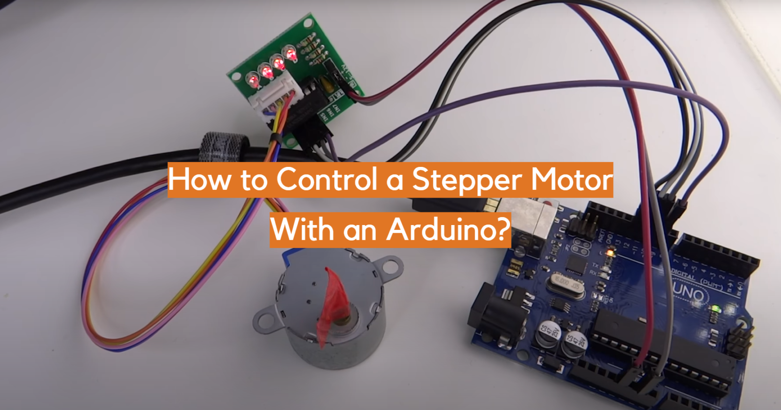
In this article, we are going to show you how to control a stepper motor with an Arduino. Stepper motors are perfect for controlling movement in projects, and they can be used in everything from 3D printers to CNC machines. We will provide a comprehensive guide on how to use an Arduino to control a stepper motor, including wiring diagrams and code examples. Let’s get started!
Arduino and Its Benefits
It is an open-source hardware development platform based on easy-to-use hardware and software. It can be used to create interactive objects or environments, and its flexibility makes it one of the most popular platforms for prototyping electronics designs.
One of its major benefits is how quickly you can get up and running with an Arduino project. With just a few inputs from sensors, motors, lights, etc., you can rapidly prototype your ideas in minutes instead of days or weeks. This has made it much easier for people to build cool projects like robots or autonomous vehicles without having to learn complicated coding languages or intricate hardware design.
The Arduino also has a wide range of accessories and components available, allowing you to customize your project in whatever way best suits your needs. From simple LED lights to powerful motors, there’s something for everyone to use on their projects. You can also easily integrate the Arduino into other systems like Raspberry Pi or BeagleBone if needed.
Finally, the open-source nature of the platform means that anyone can contribute to it and benefit from others’ work. As such, there is a strong community of developers who are constantly creating new libraries and applications for the platform that make it easier than ever to get started with an Arduino project. With its low cost, wide range of components and accessories, and user-friendly software, the Arduino can be used to create amazing projects in virtually any field. [1]
Various Types of Motors
Motors enable a lot of the functions and automation we enjoy in everyday life. Motors are used to power a wide variety of devices from simple toys to complex robots. They can be found in many different shapes, sizes, and types.
DC Motor
The stator has permanent magnets inside that have poles with opposite polarity which help generate the magnetic field required to run the motor. The rotor has coils of wire that are wound around an axle and when a current passes through these coils they produce their own magnetic field. This causes the rotor to rotate in relation to the stator’s magnetic field, thus generating mechanical energy or movement.
DC motors are used in many applications including robotics, vehicles, machines, toys and more. They are valued for their reliability and straightforward design, as well as their variable speed control capabilities. They have a wide range of torque speeds and can be used to drive heavy loads at relatively low speeds or light loads at very high speeds. DC motors are also fairly efficient compared to other types of electric motors, making them an ideal choice for many applications.
Servo Motor
It consists of a head with a motor attached on one end and a gearbox assembly on the other. The gearbox converts the high-speed output from the motor into slower, more precise movements. Servo motors are most commonly used in applications requiring precise positioning and repeatability such as robotics, automation systems, CNC machines and other motion control systems. They are also used in aircraft flight control systems where they provide critical inputs for controlling the position of surfaces like flaps and elevators. Servo motors have a wide range of power requirements depending on their application but typically operate at 12V or 24V DC. They are available in a variety of sizes and shapes depending on the application.
Servo motors have several components that work together to ensure accurate positioning. The most commonly used component is the encoder, which provides feedback signals to the motor control system about its position or speed. This information is then compared with desired values set by the user and used to adjust the output of the motor accordingly. Other components of servo motors include potentiometers, limit switches, brakes, tachometers and current sensors. Specialized servos may also include additional components such as magnets or optical sensors for enhanced accuracy and better performance in high-speed applications.
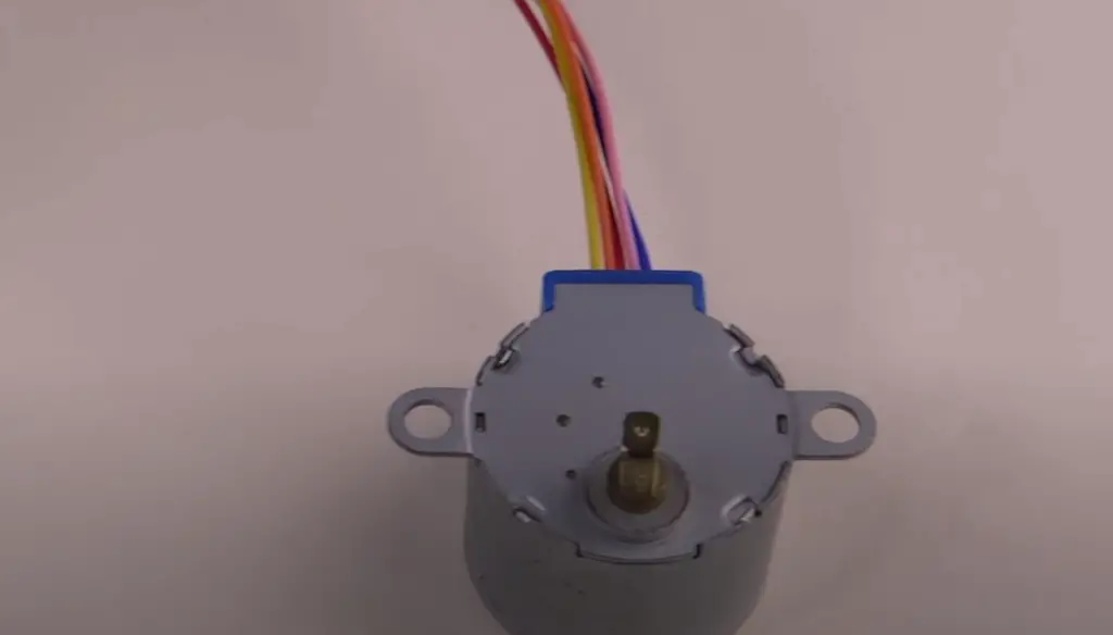
Stepper Motor
Stepper motors are employed in a wide variety of applications, such as 3D printers, CNC machines and robots.
The operation of a stepper motor is based on the fact that it behaves like an electromagnet when energized. When current passes through its windings, it creates a magnetic field which interacts with the permanent magnets located inside the motor housing to cause rotational movement. This process is known as “stepping” because each pulse of electricity causes the rotor to move one step or angle increment at a time.
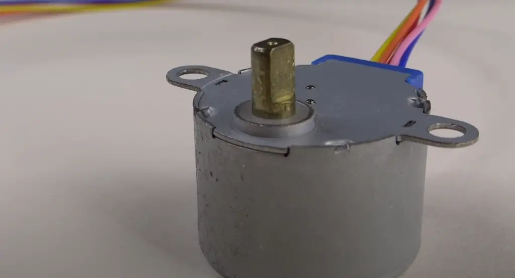
The size of each step is determined by the number of teeth on the rotor and the number of poles (coils) on the stator. The more teeth, coils, or poles a motor has, the more precise it can be in its motion.
Stepper motors are typically used in open-loop control systems due to their ability to accurately move to predetermined positions without the need for feedback. They are also ideal for applications that require precise positioning such as robotics and automation. The main advantage of using stepper motors is that they offer very high torque at low speeds which make them suitable for a variety of heavy-duty applications.
In addition to being used in motion control applications, stepper motors are also used in many other areas including medical devices, pumps, clocks and watches, and aerospace. [2]
Controlling a NEMA17 Stepper Motor With Arduino
Now that you know more about Arduino and motors, let’s dive into the specifics of controlling a NEMA17 stepper motor with an Arduino.
NEMA17 stepper motors are one of the most commonly used stepper motors, due to their size and high torque. These motors are larger than NEMA 8 or NEMA 14 sized steppers, and therefore provide more power and torque. They also have a higher torque-to-inertia ratio, which makes them ideal for applications where fast acceleration is required.
As for the physical size of the motor, NEMA17 motors have a body length of 1.7-2.3 inches. Generally, a NEMA17 stepper motor has 200 steps or 1.8 degrees of resolution per step. However, there are also models that boast 400 steps with 0.9 degrees of accuracy per step!
Before you get to configure your stepper motor however, you’ll need to find an appropriate driver for it. The driver is an important part of the equation, as it will be responsible for manipulating current to provide motion. Once you choose your driver, you’ll need to power it and connect it to the Arduino board.
Once your hardware is all hooked up, you’re ready to start coding! Before that however, it’s important to understand what kind of commands you can send from the Arduino. Generally speaking, the most suitable of drivers is A4988, which is capable of controlling up to two stepper motors.
While the A4988 contains a peak current rating of 2A per coil, it is encouraged to maintain this at 1A, although if you have effective cooling for the IC then it can be increased up to its maximum of 2A.
The A4988 stepper driver, just like all others, is equipped with a current limiting feature which makes it incredibly convenient to adjust the maximum amount of current your motor will draw. For example, you can connect an engine that has been rated for 2.5A and limit the driver’s current at 1.5A so as not to exceed its capacity while still allowing you to use it effectively!
If the motor current rating is lower than what’s set on the driver, then it will cause your motor to overheat. To avoid this issue altogether, aim for a good match between your motor’s and driver’s ratings.
Now let’s list what exactly will you need:
- Stepper Motor NEMA 17
- A4988 Stepper Driver
- DRV8825 Stepper Driver
- TMC2208 Stepper Driver
- Arduino CNC Shield
- Arduino Uno
Once you have all the components, it’s time to connect A4988 and stepper motor to your Arduino. At the upper right of your driver you’ll find both VMOT and GND pins; this is where we attach our power source which can have a voltage ranging from 8 to 36V. We suggest you use a decoupling capacitor across these two pins as a safety measure against spikes in voltage. Make sure that the electrolytic capacitor has no less than 47uF capacity for optimal results. Next, are the four pins where we connect the stepper motor. The motor’s first phase is connected to the 1A and 1B pins, while its second phase is attached to the 2A and 2B pins.
If you’re struggling identifying wires from the motor, don’t worry. You can identify those by rotating the shaft of the stepper motor by hand, and then connecting two wires to each other.
And if you have a multimeter on hand, you can measure the continuity between phases. This will give you a reliable indication of where to place your wires without having to guess or rotate the motor by hand.
The next thing we have is the IC or logic power supply pins, VDD and GND. These can be from 3V to 5V. On the other side we have the Step and Direction pins. These can be connected to any pin on the Arduino board. The Direction pin is used to select the rotation direction of the motor. The Step pin is used to control how many steps the motor takes.
Next, connect the Sleep and the Reset pins on the A4988 to the Arduino board. These two pins will be used to enable or disable the power of the driver, as well as resetting it when needed. The easiest approach to enable the driver is simply by connecting these two pins together, as long as we won’t be using those pin functions anyway.
Moreover, MS1, MS2 and MS3 are three pins responsible for selecting the step resolution of our motor. These pins are responsible for setting the driver to Full Step, Half Step or 1/4 step mode. If all three pins are disconnected, the driver will work in Full Step mode for example.
Now that all of your hardware is connected and ready, it’s time to adjust the current limit of the driver. On the A4988 stepper driver, you can find a potentiometer to adjust the current limit. Rotating the potentiometer clockwise increases the current, while rotating it counter clockwise decreases it. It is important to adjust the current according to your stepper motor capacity and not exceed its rating. Usually you should start with a low current of about 0.5A up to 1A, although if you have effective cooling for the IC then it can be increased up to its maximum of 2A. For more precise calculations use the following code:
Current Limit = Vref / (8 x Rcs)
Where Vref is the voltage of the potentiometer, and Rcs is the current sense resistor values found on A4988.
Finally, when all components are connected correctly and your current limit is set correctly, you can write some code in Arduino IDE which will enable us to control our stepper motor! This can be done both with using and without using a library.
Configuring Stepper Motor Using a Library
The most basic code is where the motor simply follows the potentiometer and rotates depending on the voltage applied to its terminals. We can also use a library called AccelStepper which simplifies a lot of your work and makes it easier for you.
#include 2
3// change this to the number of steps on your motor4#define STEPS 1005
6// create an instance of the stepper class, specifying// the number of steps of the motor and the pins it’s8// attach to9Stepper stepper(STEPS, 8, 9, 10, 11);10
11// the previous reading from the analog input12int previous = 0;13
14void setup() {15 // set the speed of the motor to 30 RPMs16 stepper.setSpeed(30);17}18
19void loop() {20 // get the sensor value21 int val = analogRead(0);22
23 // move a number of steps equal to the change in the24 // sensor reading25 stepper.step(val – previous);26
27 // remember the previous value of the sensor28 previous = val;29}
Controlling two stepper motors at the same time
If you have an idea of a more complicated project or need to control two stepper motors at the same time, it is possible with an Arduino board. For this you will need a AccelStepper library.
#include
// Define the stepper motor and pins
AccelStepper stepper1(1, 2, 5); // (Typeof driver: with 2 pins, STEP, DIR)
AccelStepper stepper2(1, 3, 6);
void setup() {
stepper1.setMaxSpeed(1000); // Set maximum speed value for the stepper
stepper1.setAcceleration(500); // Set acceleration value for the stepper
stepper1.setCurrentPosition(0); // Set the current position to 0 steps
stepper2.setMaxSpeed(1000);
stepper2.setAcceleration(500);
stepper2.setCurrentPosition(0);
}
void loop() {
stepper1.moveTo(800); // Set desired move: 800 steps (in quater-step resolution that’s one rotation)
stepper1.runToPosition(); // Moves the motor to target position w/ acceleration/ deceleration and it blocks until is in position
stepper2.moveTo(1600);
stepper2.runToPosition();
// Move back to position 0, using run() which is non-blocking – both motors will move at the same time
stepper1.moveTo(0);
stepper2.moveTo(0);
while (stepper1.currentPosition() != 0 || stepper2.currentPosition() != 0) {
stepper1.run(); // Move or step the motor implementing accelerations and decelerations to achieve the target position. Non-blocking function
stepper2.run();
//
//
}
}
Using the AccelStepper library will make it much easier to control two or more stepper motors at the same time, allowing you to write a single code for both of them and have precise results. The setup is also similar to what we did for one stepper motor above – we just need another driver IC with its own connections and Arduino pins.
Configuring Stepper Motor’s Speed
Now let’s talk about how to configure our stepper motor’s speed. We already talked about how a potentiometer affects the speed of the motor, but how do you configure that all?
#include 2
3const int stepsPerRevolution = 200; // change this to fit the number of steps per revolution4// for your motor5
6
7// initialize the stepper library on pins 8 through 11:8Stepper myStepper(stepsPerRevolution, 8, 9, 10, 11);9
10int stepCount = 0; // number of steps the motor has taken11
12void setup() {13 // nothing to do inside the setup14}15
16void loop() {17 // read the sensor value:18 int sensorReading = analogRead(A0);19 // map it to a range from 0 to 100:20 int motorSpeed = map(sensorReading, 0, 1023, 0, 100);21 // set the motor speed:22 if (motorSpeed > 0) {23 myStepper.setSpeed(motorSpeed);24 // step 1/100 of a revolution:25 myStepper.step(stepsPerRevolution / 100);26 }27}
Configuring the Motor Without Using a Library
If you want to try out coding your motor without using a library, you can simply use a few digitalWrite() commands. All you need is to set the direction and Step pins’ values to activate it.
#define stepPin 2
#define dirPin 5
void setup() {
// Sets the two pins as Outputs
pinMode(stepPin,OUTPUT);
pinMode(dirPin,OUTPUT);
}
void loop() {
digitalWrite(dirPin,HIGH); // Enables the motor to move in a particular direction
// Makes 200 pulses for making one full cycle rotation
for(int x = 0; x < 800; x++) {
digitalWrite(stepPin,HIGH);
delayMicroseconds(700); // by changing this time delay between the steps we can change the rotation speed
digitalWrite(stepPin,LOW);
delayMicroseconds(700);
}
delay(1000); // One second delay
digitalWrite(dirPin,LOW); //Changes the rotations direction
// Makes 400 pulses for making two full cycle rotation
for(int x = 0; x < 1600; x++) {
digitalWrite(stepPin,HIGH);
delayMicroseconds(500);
digitalWrite(stepPin,LOW);
delayMicroseconds(500);
}
delay(1000);
This is a more difficult option since it requires more lines of code and the calculations necessary for different speeds can get complicated. [3], [4], [5]
Various Projects You Can Make Using Stepper Motors
Now that you have a better understanding of how to control a stepper motor with an Arduino, let’s look at various projects that you can make using stepper motors.
Wi-Fi Controlled FPV Rover Robot Project
One of the most interesting projects you can create using stepper motors, an Arduino and a Wi-Fi connection is an FPV Rover Robot. This type of robot uses two wheels to move around. It has a camera mounted on it that you can control via your laptop or smartphone using Wi-Fi.
To create this robot, you will need the following components:
- UNO;
- ESP8266;
- Stepper motor;
- Android device;
- Power bank;
- Internet connection;
- Acrylic sheet;
If you’re a fan of robotics and want to create a robot that you can control over the internet, then this project is perfect for you. The first step in getting started with this project is programming your Arduino board. You can use the popular Arduino IDE software on your computer to do this.
Satellite Tracker Project
Another interesting application of a stepper motor with an Arduino is in a satellite tracker project. In this project, the Arduino will use its ability to control the speed and direction of a stepper motor to precisely follow the movement of a satellite across the sky and produce a 3D picture of its trajectory.
The project will involve connecting the stepper motor to an Arduino and programming it with a series of movements that accurately track the satellite’s movement. This project incorporates an array of components such as a satellite antenna, Arduino UNO board, stepper motor and ball bearing to bring your invention to life.
CNC Router using Arduino UNO
This is yet another way to make use of Arduino UNO for controlling a stepper motor.
It has become popular in the Maker community due to its ease of use and affordability.To create this amazing system, we have employed Arduino UNO, stepper driver, stepper motors, handles, and printers.
Arduino 3D Printer
Not only can you control a 3D printer using Arduino but you also have the opportunity to customize and optimize your 3D printing projects. College students can take advantage of this project by utilizing Arduino UNO, 3D Printer, Acrylic Sheets, stepper motor, battery and Arduino Mega 2560 to print any desired 3D image programmed in the Arduino IDE. With such a comprehensive set of components at their disposal, students have the potential to explore limitless possibilities! [6]
FAQ
What is a stepper motor?
A stepper motor is an electric motor that can be precisely controlled to rotate a specific number of degrees. It works by energizing coils within the motor in a sequence, which causes the rotor to turn and move incrementally. This type of control makes them ideal for robotics projects, where exact positioning is needed.
Using an Arduino to control a stepper motor has several advantages: it’s easy to program, allows for precise control of movement, and provides built-in protection against overloading or overheating. Furthermore, there are many libraries available that simplify programming tasks so even novice developers can quickly learn how to program their own project without needing to deep dive into the details of programming.
How do you control a stepper motor?
Controlling a stepper motor with an Arduino is surprisingly easy. By using a few pieces of hardware and some code, you can control the number of revolutions a stepper motor will turn, its direction of rotation, and even how fast it moves.
To begin controlling your stepper motor, you will need to connect it to an Arduino board. After wiring up your stepper motor, you should then install any necessary libraries on your computer that are required for the type of driver used by your specific motor. After this has been done, upload the desired code to the Arduino and once complete, you can now start sending commands from your computer or other device to control your stepper motor.
One key thing to consider when controlling a stepper motor is the type of driver used by your specific motor and the required libraries to use with it. Different drivers require different libraries, so ensure that you have the correct library installed before attempting to control your stepper motor.
How to make a stepper motor spin with Arduino?
Using an Arduino to control a stepper motor is a great way to add precision and accuracy to a wide variety of projects. It’s easy to get started too – all you need is the right hardware: an Arduino board, a stepper motor driver, and the appropriate power supply for your motor. The first step in getting your setup up and running is connecting the components together.
The speed of the motor is controlled by the potentiometer on the driver board. The higher potentiometer value will increase the speed of the motor. You can also change the direction of rotation by reversing the polarity applied to the motor’s terminals.
Can you control a motor with an Arduino?
Yes, you can control a motor with an Arduino. You can use the Arduino to control a stepper motor by sending it signals through its digital pins. The type of signal that needs to be sent depends on the type of motor being used. For instance, four-wire stepper motors require Pulse Width Modulation (PWM) signals to control the speed and direction while two-wire stepper motors require square wave pulses instead.
How does Arduino code to connect to the stepper motor?
In order to connect the Arduino code to a stepper motor, you must first determine which type of stepper motor you will be using. The three most common types are bipolar, unipolar and hybrid steppers. Depending on your motor type, wiring configurations can vary.
Once you have determined the type of stepper motor, you will need to configure the Arduino code accordingly. The code will use digital pins and analog outputs from the Arduino board in order to control the various aspects of stepper motors such as direction and speed. You can use either Pulse Width Modulation (PWM) or Direct Current (DC) signals for this purpose depending on what is required for your particular setup.
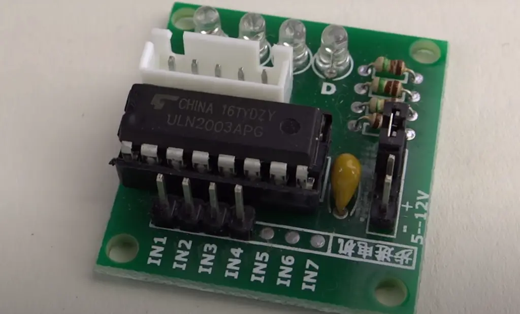
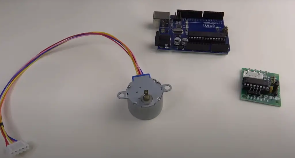
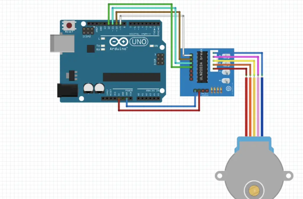
Useful Video: 28BYJ-48 stepper motor and ULN2003 Arduino (Quick tutorial for beginners)
Conclusion
Arduino is a great platform to use as a stepper motor controller. It is able to reliably control the speed, direction, and position of the motor, allowing it to be used in many automated applications. The flexibility of Arduino also allows for custom programs or libraries to add extra functionality and features. However, choosing an appropriate power supply and taking precautions against electrical noise are important considerations when using Arduino for controlling a stepper motor.
Stepper motors can be used for a large number of applications, and the Arduino makes it easier than ever to get started with these motors. Not only is it easy to use, but the superior features of the Arduino makes it a great choice for controlling all types of motors.
In this article, we have covered the basics of stepper motors and how to control them with an Arduino. We have provided information about choosing a power supply and protecting against electrical noise, as well as several examples for getting started.
Remember that understanding how the different types of motors behave—and selecting one accordingly—is crucial for successful operation. By following these steps and keeping safety in mind at all times, you can easily create powerful stepper motor controllers with Arduino that will serve you well in your projects! Good luck!
References
- https://learn.sparkfun.com/tutorials/what-is-an-arduino/all
- https://www.seeedstudio.com/blog/2019/04/01/choosing-the-right-motor-for-your-project-dc-vs-stepper-vs-servo-motors/
- https://howtomechatronics.com/tutorials/arduino/stepper-motors-and-arduino-the-ultimate-guide/
- https://docs.arduino.cc/learn/electronics/stepper-motors
- https://www.instructables.com/Controlling-a-Stepper-Motor-with-an-Arduino/
- https://www.watelectronics.com/arduino-projects/