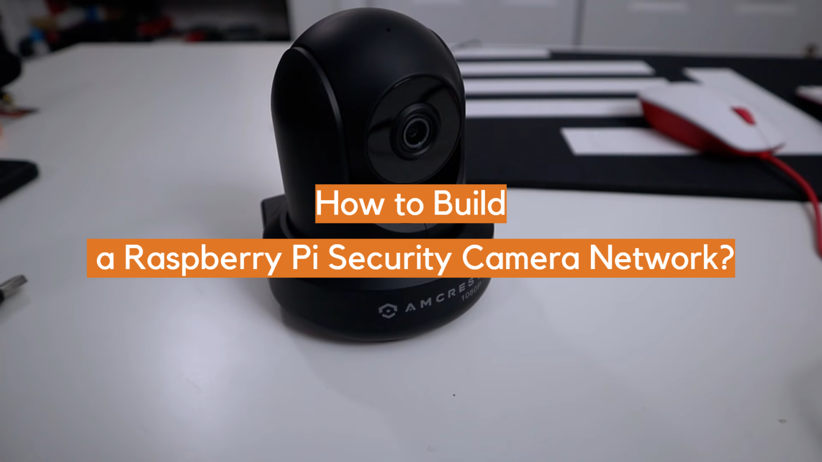
With its compact form factor and impressive computational capabilities, the Raspberry Pi proves to be an exceptional platform for crafting a comprehensive security camera network that fits your specific requirements. This article will guide you through the step-by-step process of building a Raspberry Pi-based security camera network, offering you an opportunity to safeguard your surroundings and belongings with an ingenious blend of technology and ingenuity.
Whether you’re a tech enthusiast seeking a DIY project or a homeowner eager to enhance your property’s security, this guide will empower you to harness the potential of the Raspberry Pi to create an efficient, cost-effective, and entirely customizable surveillance system.
From selecting the appropriate hardware components to configuring software and accessing live camera feeds remotely, each facet of the journey will be meticulously outlined, ensuring that even those with limited technical experience can embark on this transformative endeavor.
Prepare to delve into the realm of innovative home security, as we embark on a journey to construct a Raspberry Pi security camera network that seamlessly melds cutting-edge technology with everyday practicality.
What Is MotionEyeOS?
One of the primary advantages of motionEyeOS is its flexibility. It supports a wide range of camera hardware, from USB webcams to dedicated camera modules, making it adaptable to various setups and budgets. This versatility has made it a favorite among hobbyists, tinkerers, and tech enthusiasts who seek an affordable and customizable home surveillance solution.
Setting up motionEyeOS is a relatively straightforward process. Users begin by installing the motionEyeOS image onto an SD card, which is then inserted into their single-board computer. After connecting a camera to the computer, they can access the web interface to configure settings such as motion sensitivity, notification triggers, and recording options. The system can be set up to send email notifications, upload images and videos to cloud storage, or even integrate with home automation systems.
Privacy-conscious individuals appreciate motionEyeOS’s local storage capabilities. Unlike many commercial surveillance solutions that rely heavily on cloud services, motionEyeOS stores data locally, allowing users to maintain control over their footage and avoid potential security breaches or unauthorized access.
MotionEyeOS also offers advanced features, such as motion detection zones, time-lapse recording, and support for external triggers like PIR sensors. Its community-driven development model means that new features and improvements are continuously being added, ensuring that the system remains relevant and up-to-date.
Building a Raspberry Pi Security Camera Network:
1. Required Equipment
Before embarking on this journey, it’s crucial to gather all the required equipment. Here’s what you’ll need:
- Raspberry Pi: The heart and brains of your security camera network;
- Raspberry Pi Camera or USB WebCam: The eyes that capture the footage;
- Power Supply: Keep your Raspberry Pi up and running;
- Micro SD Card (8GB+ Recommended): Store your MotionEye OS and captured data;
- Ethernet Cable (Recommended) or Wi-Fi: Establish a network connection;
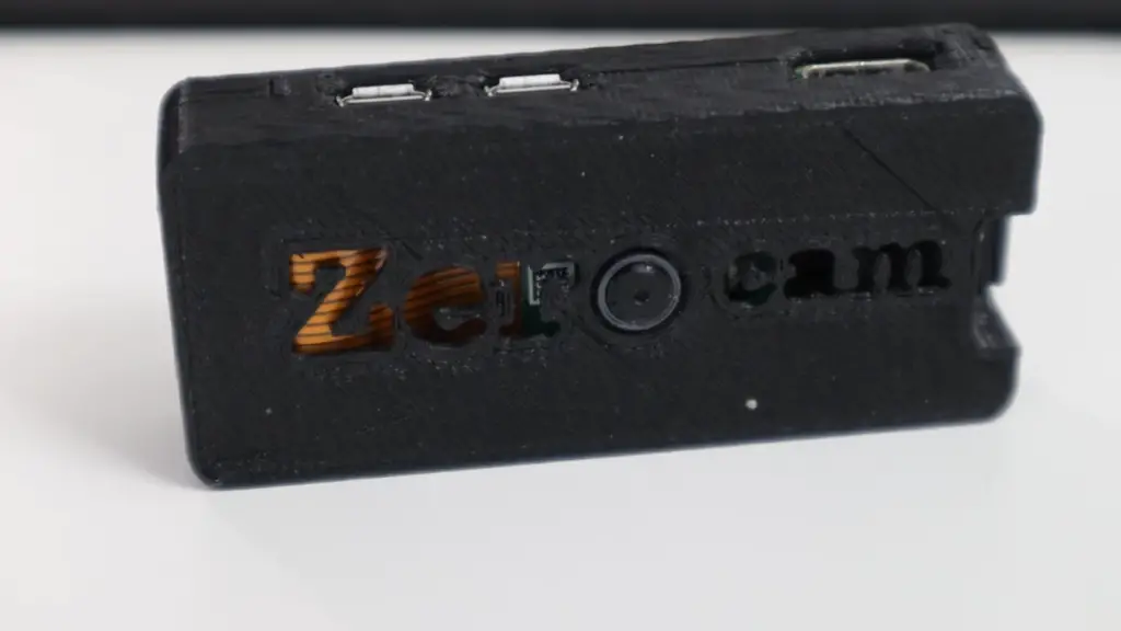
- Raspberry Pi Case (Optional): Protect your Raspberry Pi from dust and damage;
2. Installing the Raspberry Pi Camera
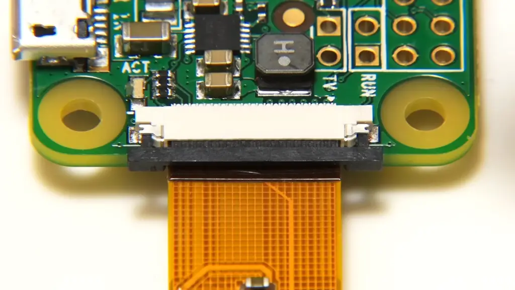
If you’ve opted for the Raspberry Pi Camera module, it’s time to install it. Follow the manufacturer’s instructions to ensure it’s securely and correctly attached to your Raspberry Pi. If you’re using a USB webcam, connect it to an available USB port on the Raspberry Pi.
3. Installing MotionEye OS
MotionEye OS is the backbone of your security camera network. Follow these steps to get it up and running:
- Download & Format the SD Card. Download the latest version of MotionEye OS from the official website. Insert the micro SD card into your computer and format it to ensure a clean slate;
- Install the MotionEye OS Image onto the SD Card. Use a tool like Etcher to write the MotionEye OS image onto the micro SD card. Once the process is complete, insert the SD card into your Raspberry Pi;
4. Booting & Setting up MotionEye OS
Power up your Raspberry Pi, and it’s time to configure MotionEye OS:
- Attach the Camera to Raspberry Pi. If you haven’t already, attach the Raspberry Pi Camera module or USB webcam to your Raspberry Pi;
- Add wpa_supplicant.conf. For wireless connectivity, create a file named wpa_supplicant.conf on the micro SD card to configure Wi-Fi settings. This step ensures your Raspberry Pi connects to your network upon boot;
- Connect To MotionEye Web Interface. Determine the IP address assigned to your Raspberry Pi by your router. Open a web browser and enter the IP address, followed by the appropriate port (usually 8765) to access the MotionEye OS web interface;
- Change Password. As a security measure, change the default password for your MotionEye OS interface to prevent unauthorized access;
- Video Device Settings. Configure the camera settings, such as resolution and frame rate, to suit your preferences and requirements;
- Customize Your Build. Explore the plethora of customization options in MotionEye OS, including themes, layouts, and more, to personalize your security camera network [2];
5. Configuring the Settings in MotionEye OS
Fine-tune your MotionEye OS settings to optimize your security camera network:
- General Settings. Set your system name, time zone, and language preferences;
- Wireless Network. If you’re using Wi-Fi, input your network credentials to ensure seamless connectivity;
- Video Device. Adjust camera-specific settings, such as brightness, contrast, and saturation;
- File Storage. Configure where your captured images and videos will be stored;
- Text Overlay. Add text overlays to your camera feeds for context or identification;
- Video Streaming. Enable streaming for live monitoring on various devices;
- Still Images. Fine-tune settings for capturing still images at specific intervals;
- Motion Detection. Set up motion detection zones, sensitivity, and actions triggered by movement;
- Motion Movies. Configure settings for recording motion-triggered videos;
- Motion Notifications. Receive alerts and notifications via email or other methods when motion is detected;
- Working Schedule. Create schedules to determine when motion detection is active or when cameras should be turned on/off;
Connect Powerboost 500C To Raspberry Pi
1. What You’ll Need
Before you begin, make sure you have the following components:
- Raspberry Pi (any model with compatible GPIO pins);
- PowerBoost 500C;
- Lithium Polymer (LiPo) battery;
- Jumper wires (typically included with the PowerBoost);
- Micro USB cable;
- Soldering iron and solder (optional, for a more secure connection);
2. Steps to Connect PowerBoost 500C to Raspberry Pi
Follow these steps to establish a reliable power connection between the PowerBoost 500C and your Raspberry Pi:
- Prepare Your PowerBoost 500C: Start by ensuring your PowerBoost 500C is powered off and disconnected from any power sources. This is a crucial safety step before proceeding;
- Connect the LiPo Battery: Attach the LiPo battery to the PowerBoost 500C. Ensure you connect the positive (+) and negative (-) terminals correctly. The PowerBoost should have labeled terminals indicating the correct polarity;
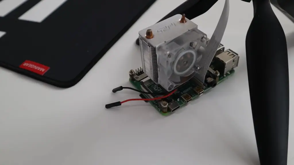
- Connect PowerBoost to Raspberry Pi: Using jumper wires or soldering, connect the following pins on the PowerBoost to the corresponding pins on the Raspberry Pi;
- Connect the 5V pin on the PowerBoost to the 5V pin on the Raspberry Pi;
- Connect the GND (Ground) pin on the PowerBoost to any of the GND pins on the Raspberry Pi;
- Connect the EN (Enable) pin on the PowerBoost to any of the GPIO pins on the Raspberry Pi. This pin allows you to control the power to the Raspberry Pi programmatically;
- Attach Micro USB Cable: Connect the micro USB cable to the USB port on the PowerBoost 500C. The other end of the cable should be connected to a power source such as a USB wall adapter or a computer;
- Power On: Power on the PowerBoost 500C. The LED indicators on the PowerBoost should illuminate, indicating that power is flowing;
- Boot Up Raspberry Pi: As the PowerBoost supplies power to the Raspberry Pi, it should boot up and start running your desired applications;
Connect SPDT Switch to Powerboost 500C
1) Understanding the Components
Before we embark on the connection process, let’s familiarize ourselves with the key components:
- PowerBoost 500C: This compact power supply module is designed to provide a stable power source for your devices, ensuring smooth operation and portability;
- SPDT Switch: The Single-Pole, Double-Throw switch is a versatile component that can connect or disconnect two separate circuits. It has three terminals: Common (COM), Normally Open (NO), and Normally Closed (NC);
- Jumper Wires: These flexible wires facilitate the connection between various components;
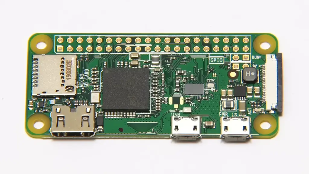
- Raspberry Pi: If you’re using the PowerBoost 500C in conjunction with a Raspberry Pi, ensure you have the necessary cables and connections established;
2) The Connection Process
Follow these steps to seamlessly connect an SPDT switch to the PowerBoost 500C:
Step 1: Prepare Your Components
Before beginning any electrical work, ensure your components are powered off and disconnected from any power sources to prevent accidents or damage.
Step 2: Identify the Terminals
Examine your SPDT switch to identify its terminals. You should have three terminals labeled as Common (COM), Normally Open (NO), and Normally Closed (NC). Familiarize yourself with their functions and positioning.
Step 3: Plan Your Connections
Determine how you want the switch to function within your project. The SPDT switch can serve various purposes, such as toggling power to a device or selecting between different modes. Plan the connections accordingly [3].
Step 4: Connect to the PowerBoost 500C:
- Connect the Common Terminal (COM): Attach a jumper wire from the Common terminal (COM) of the SPDT switch to the EN (Enable) pin on the PowerBoost 500C. This connection will allow you to control the power supply;
- Connect the Normally Open Terminal (NO): Attach a jumper wire from the Normally Open terminal (NO) of the SPDT switch to the GND (Ground) pin on the PowerBoost 500C. This connection will complete the circuit when the switch is activated;
- Connect the Normally Closed Terminal (NC): Attach a jumper wire from the Normally Closed terminal (NC) of the SPDT switch to the GND (Ground) pin on the PowerBoost 500C. This connection will remain closed when the switch is in its default position;
Step 5: Test Your Connection
With the connections in place, power on your components and test the functionality of the SPDT switch. When the switch is in its default position, the circuit between NC and GND should be closed, allowing power to flow. When the switch is activated and moved to its opposite position, the circuit between NO and GND should close, interrupting the power supply.
Step 6: Integrate with Your Project
Depending on your project’s requirements, you can integrate the SPDT switch and PowerBoost 500C combination to achieve various outcomes. Whether you’re controlling power to a device, switching between different operational modes, or implementing a safety feature, the SPDT switch offers valuable versatility.
3) Practical Applications
The connection of an SPDT switch to the PowerBoost 500C opens the door to a multitude of practical applications:
- On/Off Control: Use the switch to toggle power to your project, conserving energy when the device is not in use;
- Mode Selection: Implement different operational modes or settings for your project, allowing users to switch between them using the SPDT switch;
- Emergency Power Cutoff: Enable a safety feature that allows you to quickly cut off power to the device in case of emergencies
- User Interaction: Provide users with a physical control interface to enhance their engagement with your project;
Connect LiPo Battery To Powerboost 500C
1) Understanding the Components
Before we delve into the connection process, let’s familiarize ourselves with the key components involved:
- PowerBoost 500C: A small and versatile power supply module designed to provide a steady power source to your devices;
- LiPo Battery: A rechargeable battery known for its high energy density and light weight, making it an excellent choice for portable projects;
- Jumper Wires: These flexible wires facilitate the connection between the LiPo battery, PowerBoost 500C, and your electronic components;
- Raspberry Pi (or other devices): Depending on your project, you might connect the PowerBoost 500C to a Raspberry Pi or another microcontroller;
2) The Connection Process
Follow these steps to successfully connect a LiPo battery to the PowerBoost 500C and power up your projects:
Step 1: Safety First
Before you begin any electrical work, prioritize safety. Ensure that all components are powered off and disconnected from any power sources to prevent accidents or damage.
Step 2: Prepare the LiPo Battery
If your LiPo battery is new or hasn’t been used for a while, make sure it is charged to an appropriate level using a LiPo battery charger. This ensures optimal performance and longevity.
Step 3: Examine the PowerBoost 500C
Inspect the PowerBoost 500C to identify its various components and ports. Note the BAT (Battery) and USB ports, as well as the EN (Enable) and GND (Ground) pins.
Step 4: Connect the LiPo Battery:
- Connect the Battery: Using jumper wires, connect the positive (+) terminal of the LiPo battery to the BAT (Battery) port on the PowerBoost 500C. Connect the negative (-) terminal of the LiPo battery to the GND (Ground) port on the PowerBoost 500C. Ensure that the polarity is correct to prevent damage;
- Configure the Jumper: On the PowerBoost 500C, there is a jumper labeled LOW and HIGH. Depending on the voltage of your LiPo battery (3.7V or 4.2V per cell), place the jumper in the appropriate position [4];
Step 5: Connect to Your Device:
- Enable Pin Connection: Connect the EN (Enable) pin on the PowerBoost 500C to a digital pin on your Raspberry Pi (or other microcontroller). This connection allows you to programmatically control the power supply;
- USB Port: Connect a micro USB cable to the USB port on the PowerBoost 500C. The other end of the cable can be connected to a power source such as a USB wall adapter or a computer;
Step 6: Test the Setup
Power on your components and test the setup. If everything is connected correctly, the LiPo battery should power your device through the PowerBoost 500C.
Benefits and Applications
The connection of a LiPo battery to the PowerBoost 500C offers several benefits and opens up a wide range of applications:
- Portability: With a LiPo battery and the PowerBoost 500C, you can create truly portable projects that can be used anywhere without relying on a constant power source;
- Field Research and Monitoring: Use this setup for outdoor data collection, environmental monitoring, and remote research projects;
- Emergency Power: Build emergency backup power solutions for critical devices, ensuring they remain operational during power outages;
- Robotics and Drones: Power your robots, drones, or remote-controlled vehicles with a lightweight and high-energy-density LiPo battery;
- Prototyping: Simplify the prototyping process by using a portable power solution that can be easily integrated into various projects;
How To Build The Simplest Raspberry Pi Security Camera Network:
1. Things You Will Need
Before we dive into the process, ensure you have the necessary components ready:
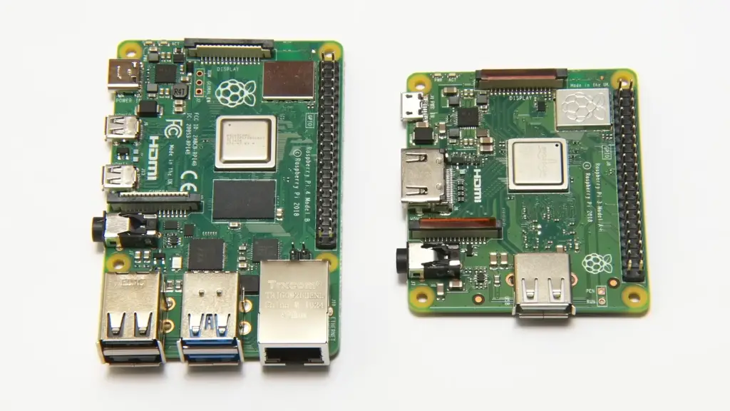
- Raspberry Pi 3 or Raspberry Pi 4: The heart of your camera network, capable of running the necessary software and handling the camera module;
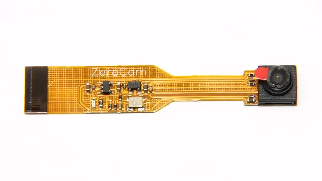
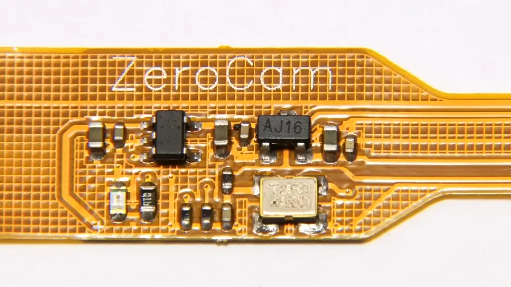
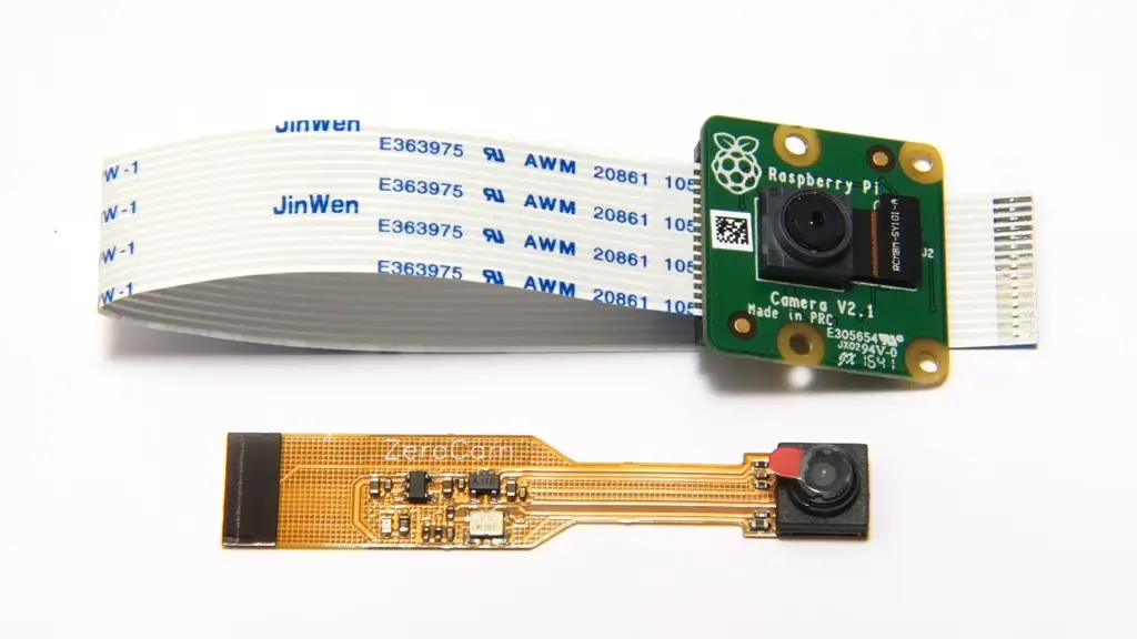
- Raspberry Pi camera module: This tiny camera offers decent image quality and is specifically designed for Raspberry Pi projects;
- Micro-USB (Raspberry Pi 3) or USB Type-C (Raspberry Pi 4) Power Adapter: To power your Raspberry Pi;
- 16 GB or 32 GB MicroSD Card with Raspberry Pi OS Flashed: The storage for your Raspberry Pi’s operating system and files;
- Network Connectivity On the Raspberry Pi: Either via Ethernet or Wi-Fi to enable communication;
- Laptop Or PC for VNC Remote Desktop or SSH Access To the Raspberry Pi: Necessary for setting up and accessing the Raspberry Pi remotely;
- Enabling the Raspberry Pi Camera Module: Before you begin, make sure the camera module is enabled in the Raspberry Pi configuration settings;
2. Installing VLC Media Player
3. Creating a Camera Server with VLC Media Player:
- Open Terminal on Raspberry Pi: Access the terminal on your Raspberry Pi and install VLC by entering the following command: sudo apt-get install vlc;
- Launch VLC: Once VLC is installed, launch it using the command cvlc;
- Set Up Streaming: To stream the camera feed, enter the following command: cvlc v4l2:///dev/video0 –v4l2-width 640 –v4l2-height 480 –sout ‘#standard{access=http,mux=ts,dst=:8080}’;
4. Streaming the Camera Feed from the Raspberry Pi Camera Server:
- Access VLC on Remote Computer: On your remote laptop or PC, open VLC and go to “Media” > “Open Network Stream”;
- Enter Stream URL: In the URL field, enter http://raspberry_pi_ip:8080 (replace raspberry_pi_ip with the actual IP address of your Raspberry Pi);
- View the Stream: Click “Play” to view the live camera feed from your Raspberry Pi’s camera module [5];
5. Starting the Camera Server on System Boot
For seamless functionality, you can configure the Raspberry Pi to start the camera server automatically on boot:
- Open Terminal: Access the terminal on your Raspberry Pi;
- Edit rc.local: Enter the following command to open the rc.local file: sudo nano /etc/rc.local;
- Add Command: Before the line exit 0, add the command to start the camera server, similar to the one used earlier: cvlc v4l2:///dev/video0 –v4l2-width 640 –v4l2-height 480 –sout ‘#standard{access=http,mux=ts,dst=:8080}’ &;
- Save and Exit: Press Ctrl + X, then Y, and finally press Enter to save and exit;
- Reboot: Reboot your Raspberry Pi for the changes to take effect: sudo reboot;
FAQ:
1. Can Raspberry Pi be used for security cameras?
Yes, Raspberry Pi can be used effectively for creating a security camera system.
2. How many IP cameras can a Raspberry Pi handle?
The number of IP cameras a Raspberry Pi can handle depends on various factors, including the Raspberry Pi model, processing power, memory, and the software being used. Typically, a Raspberry Pi can handle one to a few IP cameras without significant performance issues.
3. What is the minimum focus distance for a Raspberry Pi camera?
The minimum focus distance for a Raspberry Pi camera module varies depending on the specific camera model. However, it’s generally around 5 cm (1.96 inches) to 8 cm (3.14 inches).
4. What is the IP address for the Raspberry Pi camera?
The IP address for a Raspberry Pi camera is assigned by your network’s DHCP server when the Raspberry Pi is connected to a local network. You can find the IP address using commands like ifconfig or by checking your router’s connected devices list.
5. How to run a Raspberry Pi camera module?
To run a Raspberry Pi camera module:
- Attach the camera module to the CSI port;
- Enable the camera in the Raspberry Pi configuration settings;
- Use software libraries like Picamera (Python) or command-line tools like raspistill and raspivid to capture photos and videos [6];
6. How to connect an IP security camera to Raspberry Pi?
To connect an IP security camera to Raspberry Pi, follow these steps:
- Connect the IP camera to the same local network as the Raspberry Pi;
- Determine the IP address of the IP camera;
- Use appropriate software or libraries to access and process the camera’s video feed;
7. Can a Raspberry Pi camera detect motion?
Yes, a Raspberry Pi camera can detect motion using software libraries or applications like MotionEyeOS. These tools analyze consecutive frames from the camera to detect changes and motion.
8. Does the Raspberry Pi have an IR sensor?
No, the Raspberry Pi itself doesn’t have a built-in IR sensor, but you can connect external IR sensors or use cameras with IR sensitivity for night vision.
9. How far can the Raspberry Pi night vision camera see?
The distance the Raspberry Pi night vision camera can see depends on factors like the camera model, the quality of the IR LEDs, and ambient lighting conditions. Generally, it’s effective for short to medium distances, around 5 to 10 meters.
10. Can Raspberry Pi run multiple cameras?
Yes, a Raspberry Pi can run multiple cameras simultaneously. However, performance may vary depending on the Raspberry Pi model and camera resolutions.
11. Can Raspberry Pi support 2 cameras?
Yes, Raspberry Pi can support two cameras by utilizing the CSI port and additional camera modules.
12. Do security cameras have IP addresses?
Yes, IP cameras (Internet Protocol cameras) have IP addresses assigned to them. These addresses allow you to access and control the cameras over a network.
13. How does a Raspberry Pi camera work?
The Raspberry Pi camera captures images or video by converting light into electronic signals. The camera’s sensor detects light, and the Raspberry Pi processes the signals to create images or video frames.
14. What protocol does the Raspberry Pi camera module use?
The Raspberry Pi camera module uses the CSI-2 (Camera Serial Interface) protocol for communication between the camera and the Raspberry Pi.
15. How to set up a Raspberry Pi webcam server?
To set up a Raspberry Pi webcam server:
- Attach a compatible USB webcam to the Raspberry Pi;
- Install necessary software like motion or MJPG-Streamer;
- Configure the software to capture and stream video;
- Access the webcam server remotely by entering the Raspberry Pi’s IP address in a web browser;
16. How many IP cameras can a Raspberry Pi handle?
The number of IP cameras a Raspberry Pi can handle simultaneously depends on factors like the Raspberry Pi model, camera resolution, and processing power. It’s advisable to start with a small number of cameras and test the performance before scaling up.
17. How much power does a Raspberry Pi camera draw?
The power consumption of a Raspberry Pi camera module depends on the camera model and usage. Generally, it can range from around 150mA to 250mA during normal operation. It’s recommended to power the Raspberry Pi adequately to ensure stable performance.
18. Can I use any model of Raspberry Pi for this project?
Yes, you can use various models of Raspberry Pi, including Raspberry Pi 3 and Raspberry Pi 4, depending on your requirements. Newer models may offer improved performance and features.
19. Do I need any programming experience to build a Raspberry Pi security camera network?
While some familiarity with basic programming concepts can be helpful, it’s not strictly necessary. Many software options offer user-friendly interfaces for configuration and setup.
20. How many cameras can I connect to a single Raspberry Pi?
The number of cameras you can connect depends on factors like the Raspberry Pi model, camera resolution, and processing power. It’s recommended to start with a small number and test the system’s performance before scaling up.
21. What software should I use to set up the camera network?
Several software options are available, such as MotionEyeOS, ZoneMinder, and Shinobi. These platforms provide easy-to-use interfaces for camera configuration and monitoring.
22. How do I access the camera feeds remotely?
You can access the camera feeds remotely through various methods, including setting up port forwarding on your router, using a Dynamic DNS service, or utilizing Virtual Private Network (VPN) connections [7].
23. Can I integrate motion detection into the camera network?
Yes, many software options allow you to configure motion detection. This feature triggers recording or alerts when movement is detected in the camera’s field of view.
24. Is night vision possible with a Raspberry Pi camera?
Yes, you can enhance night vision capabilities by using a camera module with infrared (IR) sensitivity and supplementing it with IR lights or LEDs.
25. How much power does the Raspberry Pi camera network consume?
Power consumption depends on the number of cameras, Raspberry Pi model, and additional hardware. Generally, a single Raspberry Pi and camera draw around 2.5W to 5W of power.
26. Can I store recorded footage on the Raspberry Pi?
Yes, you can store recorded footage on the Raspberry Pi’s storage device. However, consider using external storage solutions or cloud storage for larger amounts of data.
27. Is this security camera network suitable for professional applications?
While this setup is great for home use and small-scale projects, professional applications may require more specialized and robust solutions.
28. Are there any legal considerations when setting up a security camera network?
Yes, it’s important to be aware of local laws and regulations regarding surveillance and privacy. Ensure you comply with applicable laws and respect the privacy of others.
29. Can I expand my camera network in the future?
Absolutely, you can expand your camera network by adding more cameras or utilizing more powerful Raspberry Pi models to accommodate your evolving needs.
30. How reliable is a Raspberry Pi-based camera network?
A Raspberry Pi-based camera network can be reliable when configured properly. However, like any technology, occasional troubleshooting and maintenance may be required.
31. What are some creative uses for a Raspberry Pi security camera network?
Apart from traditional security monitoring, you can use the network for baby monitoring, pet surveillance, home automation triggers, and even wildlife observation.
Useful Video: DIY Raspberry PI Surveillance System with MotionEyeOS
References
- https://pimylifeup.com/raspberry-pi-security-camera/
- https://littlebirdelectronics.com.au/guides/140/build-a-raspberry-pi-security-camera
- https://linuxhint.com/build-a-raspberry-pi-security-camera-network/
- https://www.instructables.com/Raspberry-Pi-as-low-cost-HD-surveillance-camera/
- https://www.tomshardware.com/how-to/raspberry-pi-security-camera
- https://pyimagesearch.com/2019/03/25/building-a-raspberry-pi-security-camera-with-opencv/
- https://www.slashgear.com/1036761/how-to-build-a-simple-raspberry-pi-home-security-camera





Leave a Reply