

A PTC (Positive Temperature Coefficient) relay with capacitor is an essential component found in many electrical devices and appliances. It plays a crucial role in motor starting applications, providing a means to overcome the initial high current required during startup.
This article aims to explore the inner workings of a PTC relay with capacitor, shedding light on its functionality and the principles behind its operation.
By understanding how this ingenious device operates, we can gain insight into its role in controlling electrical currents, protecting equipment, and ensuring the smooth and efficient operation of various electrical systems.
What Is A PTC Relay?
Definition and Purpose
The “positive temperature coefficient” refers to the characteristic of certain materials to exhibit a sharp increase in resistance as their temperature rises. This unique property allows PTC relays to regulate the current flow and act as self-resetting protectors.
Operation and Working Principle
The working principle of a PTC relay revolves around the PTC thermistor, a vital component within the device. A PTC thermistor is made from a semiconductor material that exhibits a sharp rise in resistance as its temperature increases. In normal operating conditions, the PTC thermistor has a low resistance, allowing current to flow freely. However, when an excessive current or high temperature is detected, the thermistor quickly heats up, causing its resistance to increase dramatically.
This increase in resistance limits the current flow through the circuit, preventing damage to the components. As the temperature decreases, the resistance of the thermistor decreases as well, allowing the circuit to return to its normal operating state. This self-resetting characteristic makes PTC relays highly reliable and eliminates the need for manual intervention to restore normal functionality.
Applications
PTC relays find applications in various industries and devices, including refrigeration systems, air conditioning units, electric motors, transformers, and heating elements. In refrigeration systems, PTC relays help protect the compressor from overheating by interrupting the circuit in the event of abnormal conditions.
Similarly, electric motors, they safeguard against overcurrent situations that can lead to motor burnout. The self-resetting nature of PTC relays ensures continuous protection without the need for constant maintenance or replacement.
How Does a PTC Relay With Capacitor Work?
A PTC relay with a capacitor, also known as a PTC start relay, is commonly used in single-phase electric motors to provide reliable and efficient starting mechanisms. It combines the functionality of a PTC relay with an additional capacitor to optimize motor performance during the startup phase. Let’s delve into how a PTC relay with a capacitor works.
The primary purpose of adding a capacitor to a PTC relay is to improve the starting torque of the motor. During the starting process, the capacitor helps create a phase shift in the current and voltage, which enhances the motor’s ability to generate sufficient torque to overcome the inertia and start rotating.
The operation of a PTC relay with a capacitor involves the following steps:
- Starting Phase: When the motor is initially switched on, the PTC relay with a capacitor allows the full current to flow through both the PTC thermistor and the start capacitor. The PTC thermistor, in its initial low-resistance state, allows the current to pass freely. Simultaneously, the start capacitor provides the necessary phase shift in the circuit;
- Transition Phase: As the motor gains speed and reaches a certain RPM (revolutions per minute), the PTC thermistor starts to heat up due to the current passing through it. The increased temperature causes the resistance of the PTC thermistor to rise rapidly, limiting the current flow. At this point, the start capacitor remains in the circuit, assisting the motor in generating enough torque for smooth acceleration;
- Running Phase: Once the motor reaches its operating speed, the PTC thermistor has heated up sufficiently, resulting in a high resistance that effectively cuts off the start capacitor from the circuit. The motor now operates using only the main winding and the run capacitor (if present), allowing it to run efficiently and maintain the desired speed;
The combination of the PTC thermistor and the capacitor in a PTC relay with a capacitor provides several benefits, including:
- Improved Starting Torque: The addition of the capacitor enhances the motor’s ability to produce adequate torque during startup, especially in applications with high load or when the motor needs to overcome initial resistance;
- Self-Regulation: Similar to standard PTC relays, the PTC thermistor in the relay with a capacitor acts as a self-regulating component. It monitors the current and temperature conditions, automatically adjusting the resistance to protect the motor from overcurrent and overheating situations;
- Energy Efficiency: By optimizing the motor’s starting torque, the PTC relay with a capacitor allows for smoother and quicker startups, reducing energy consumption and stress on the motor;
PTC relays with capacitors are commonly used in a wide range of applications, including refrigerators, air conditioners, compressors, and other single-phase motor-driven devices. Understanding their operation and benefits can help ensure the proper selection and utilization of these relays, leading to improved motor performance and longevity.
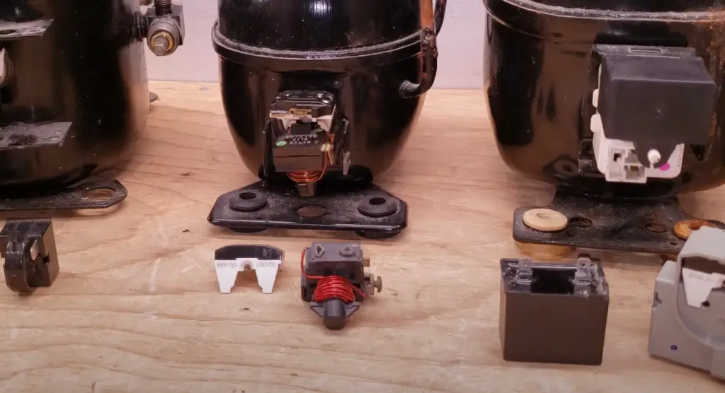
How Does a Refrigerator PTC Relay Work and Function?
A refrigerator PTC (Positive Temperature Coefficient) relay is an essential component in the refrigeration system that helps protect the compressor and ensure efficient operation [2]. It is responsible for controlling the electrical current flow to the compressor based on the temperature conditions inside the refrigerator. Let’s explore how a refrigerator PTC relay works and functions.
The primary purpose of a refrigerator PTC relay is to provide start-up assistance to the compressor while protecting it from potential damage caused by excessive current or overheating.
Here is a step-by-step explanation of its operation:
- Start-Up Phase: When the refrigerator is initially turned on, the PTC relay allows full electrical current to flow through both the start winding and the main winding of the compressor. The start winding provides the necessary extra torque to start the compressor, while the main winding maintains the motor’s operation once it is up and running;
- PTC Thermistor Activation: The PTC relay contains a PTC thermistor, which is a temperature-sensitive resistor. As the current passes through the PTC thermistor, it begins to heat up. As the temperature increases, the resistance of the PTC thermistor also rises;
- Increased Resistance: As the PTC thermistor’s resistance increases, it limits the current flow to the start winding. This reduced current to the start winding decreases the additional torque provided, ensuring that the start winding does not stay energized for an extended period;
- Main Winding Operation: Simultaneously, the main winding remains energized and continues to power the compressor. The PTC relay effectively switches the electrical circuit from the start winding to the main winding once the compressor is running. This transition ensures that the compressor operates efficiently and does not draw excessive current;
- Self-Regulation: The PTC relay acts as a self-regulating component. As the PTC thermistor reaches a certain temperature, its resistance stabilizes, maintaining a suitable current level for the compressor’s normal operation. This self-regulation feature helps prevent overcurrent situations that could lead to compressor damage;
- Cooling Down and Resetting: When the compressor is turned off or stops running due to reaching the desired temperature, the PTC thermistor cools down, reducing its resistance. This allows the relay to reset itself and prepare for the next startup cycle;
The refrigerator PTC relay plays a vital role in ensuring the proper functioning and longevity of the compressor. By controlling the current flow during startup and maintaining optimal operating conditions, it helps protect the compressor from potential damage caused by excessive current or overheating.
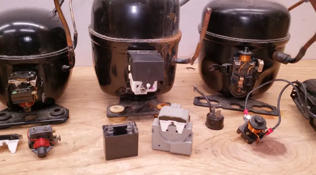
Testing of PTC Relay In A Refrigerator
Testing a PTC (Positive Temperature Coefficient) relay in a refrigerator is essential to ensure its proper functioning and to troubleshoot any issues related to the relay.
Here is a step-by-step guide on how to test a PTC relay in a refrigerator:
- Access the Relay: Locate the PTC relay, which is usually located near the compressor at the back of the refrigerator. Depending on the model, you may need to remove a protective cover or access panel to reach the relay;
- Inspect for Physical Damage: Visually inspect the PTC relay for any signs of physical damage, such as burn marks, melted components, or loose connections. If you notice any visible damage, the relay may need to be replaced;
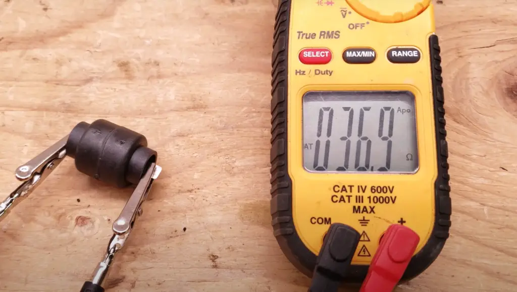
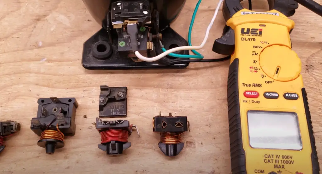
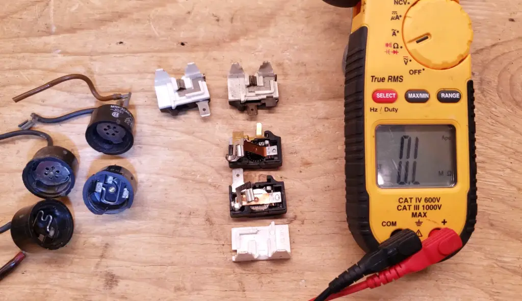
- Check for Continuity: Using a multimeter set to the continuity or resistance mode, check for continuity across the relay’s terminals. The PTC relay typically has three terminals labeled as Common (C), Start (S), and Run (R). Test the continuity between each terminal combination: C-S, C-R, and S-R. If you get a continuous (zero) reading on the multimeter for all combinations, the relay is functioning correctly. If you get an open (infinite) reading or a reading other than zero, it indicates a faulty relay that needs replacement;
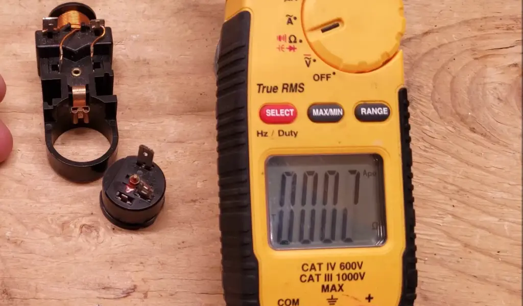
- Measure Resistance: Set the multimeter to the resistance mode and measure the resistance of the PTC relay. Place one probe on the Common (C) terminal and the other probe on the Start (S) terminal. The multimeter should display a resistance value. Consult the refrigerator’s manufacturer specifications to determine the acceptable resistance range for the PTC relay. If the measured resistance falls outside the specified range, it indicates a faulty relay;
- Check Temperature Sensing: The PTC relay’s primary function is temperature sensing. You can simulate a temperature change to observe the relay’s response. Use a hairdryer or a heat gun to apply heat directly to the PTC thermistor of the relay. Monitor the resistance readings on the multimeter while gradually increasing the temperature. The resistance should increase as the temperature rises, indicating that the PTC thermistor is functioning correctly;
Troubleshooting a PTC Relay With Capacitor
Here are some troubleshooting steps to follow:
- Visual Inspection: Start by inspecting the PTC relay and capacitor for any visible signs of damage, such as burnt or melted components, loose connections, or physical cracks. If you notice any abnormalities, it may indicate a faulty or damaged relay that requires replacement;
- Electrical Continuity: Use a multimeter set to the continuity or resistance mode to check the continuity of the PTC relay. Ensure that the refrigerator is unplugged before performing this test. Place one probe on each terminal of the relay (including the capacitor terminals, if applicable). A continuous reading (near zero resistance) indicates proper continuity, while an open or infinite reading suggests a faulty relay;
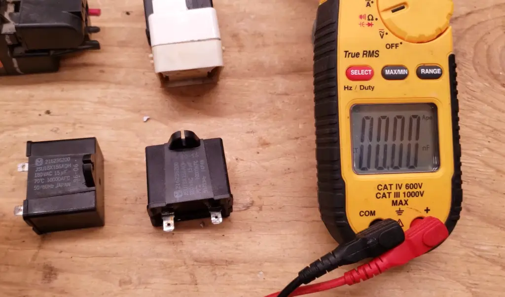
- Capacitor Testing: If the PTC relay has a capacitor, you can test its functionality using a capacitor tester or a multimeter with a capacitance measurement mode. Follow the manufacturer’s instructions for the specific testing method. Ensure the capacitor is discharged before testing, as capacitors can hold a charge even when the power is disconnected;
- Measure The Capacitance Value Of The Capacitor. Compare the measured value with the manufacturer’s specifications to ensure it falls within an acceptable range. A significant deviation from the specified capacitance may indicate a faulty capacitor that needs replacement;
- Temperature Sensing: PTC relays rely on temperature changes to regulate the current flow. You can simulate temperature changes to assess the relay’s response. Use a hairdryer or a heat gun to apply heat directly to the PTC thermistor of the relay. Monitor the resistance readings on the multimeter while gradually increasing the temperature. The resistance should increase as the temperature rises, indicating that the PTC thermistor is functioning correctly;
- Wiring and Connections: Check the wiring and connections of the PTC relay and capacitor to ensure they are secure and properly connected. Loose or damaged wiring can lead to issues with the relay’s operation. Ensure that all connections are tight and free from corrosion or debris;
- Professional Assistance: If the troubleshooting steps mentioned above do not resolve the issue or if you are uncertain about performing further tests, it is recommended to seek professional assistance from a qualified technician or contact the refrigerator manufacturer’s customer support. They can provide expert guidance and help diagnose and resolve more complex problems with the PTC relay and capacitor;
FAQ:
1. How does the PTC relay operate?
A PTC relay operates by utilizing a PTC thermistor, which is a temperature-sensitive resistor. In normal operating conditions, the PTC thermistor has a low resistance, allowing current to flow through the relay without obstruction.
However, when an excessive current or high temperature is detected, the PTC thermistor rapidly heats up, causing its resistance to increase dramatically. This increase in resistance limits the current flow, protecting the circuit or device connected to the relay. Once the temperature decreases, the resistance of the PTC thermistor decreases as well, allowing the circuit to return to its normal operating state.
2. What is a PTC capacitor?
There is no specific component called a “PTC capacitor”. PTC refers to a Positive Temperature Coefficient, which is a characteristic of certain materials that exhibit an increase in resistance with an increase in temperature. Capacitors, on the other hand, are passive electronic components used to store and release electrical energy.
They consist of two conductive plates separated by a dielectric material. While PTC thermistors and capacitors are separate components, they can be used together in certain applications, such as in PTC start relays for electric motors, to enhance motor performance during startup.
3. What is the function of the PTC starter relay?
The function of a PTC starter relay is to provide starting assistance to electric motors, particularly single-phase motors. It combines the functionality of a PTC relay and a start capacitor. The PTC starter relay helps generate the necessary torque to overcome the initial inertia and start the motor, while also protecting the motor from excessive current during the startup process.
Once the motor reaches its operating speed, the relay switches off the start winding and transitions to the run winding, allowing the motor to run efficiently.
4. How does a start capacitor relay work?
A start capacitor relay, also known as a PTC start relay, operates by utilizing a start capacitor in conjunction with a relay. The start capacitor provides an extra boost of energy to the motor during startup, helping it overcome initial inertia and start rotating. The relay controls the electrical circuit, allowing the start capacitor to be connected to the motor’s start winding only during startup [3].
Once the motor reaches its operating speed, the relay switches off the start capacitor, ensuring that it does not remain energized during normal operation. This arrangement improves motor starting torque and efficiency.
5. Can I use a start capacitor without a resistor?
In general, it is not recommended to use a start capacitor without a resistor or a relay. The resistor is used in conjunction with the start capacitor to prevent the capacitor from remaining connected to the motor’s start winding for an extended period. Without the resistor or a relay, the start capacitor would remain energized, which can cause overheating and potential damage to the motor. The resistor helps ensure that the start capacitor is disconnected once the motor reaches its operating speed.
6. What is the disadvantage of capacitor start?
One disadvantage of capacitor start systems is that they require additional components, such as a start capacitor and a start winding, which can increase the complexity and cost of the motor. Additionally, capacitor start systems may have lower power factor compared to other motor starting methods, which can affect the overall efficiency of the motor. Furthermore, capacitor start motors may have limitations in terms of torque and starting capability for certain applications.
7. How do you test a PTC start relay?
To test a PTC start relay, follow these steps:
- Disconnect the power supply to the relay and ensure it is no longer receiving any electrical current.
- Use a multimeter set to the continuity or resistance mode;
- Identify the relay’s terminals and refer to the manufacturer’s documentation or markings on the relay for terminal identification;
- Check for continuity between the common (C) terminal and the start (S) terminal. There should be low resistance or continuity;
- Check for continuity between the common (C) terminal and the run (R) terminal. There should be high resistance or no continuity;
- If the relay fails these continuity tests, it indicates a faulty relay that needs replacement;
8. What is the resistance of a PTC start relay?
The resistance of a PTC start relay can vary depending on the specific relay and its design. However, typically, the resistance of a PTC start relay falls within the range of a few ohms to several tens of ohms. It is important to consult the manufacturer’s specifications or documentation for the specific resistance values applicable to a particular PTC start relay.
9. What is the voltage of PTC?
The voltage of a PTC (Positive Temperature Coefficient) thermistor depends on the application and the specific PTC thermistor being used. PTC thermistors are available in various voltage ratings to suit different requirements. Common voltage ratings for PTC thermistors range from a few volts to several hundred volts. It is crucial to select a PTC thermistor with a voltage rating that matches the electrical system or circuit it will be used in.
10. Which is better – NTC or PTC thermistor?
The suitability of NTC (Negative Temperature Coefficient) or PTC thermistors depends on the specific application and the intended use.
Both types have their advantages and are used in different scenarios:
- NTC thermistors: These thermistors have a negative temperature coefficient, meaning their resistance decreases as the temperature rises. NTC thermistors are commonly used for temperature sensing and compensation applications, such as in thermostats, temperature controllers, and temperature monitoring systems;
- PTC thermistors: These thermistors have a positive temperature coefficient, meaning their resistance increases as the temperature rises. PTC thermistors are often used for overcurrent protection, inrush current limiting, and motor starting applications, such as in PTC start relays and fuses;
The choice between NTC and PTC thermistors depends on the specific requirements of the application and the desired functionality.
11. What makes a relay get hot?
Several factors can cause a relay to get hot:
- Excessive current: If the relay is carrying a higher current than its rated capacity, it can lead to increased resistance and cause the relay to heat up;
- Voltage spikes: Rapid voltage fluctuations or spikes can generate heat in the relay, particularly if it is not designed to handle high voltage transients;
- Poor contact: If the relay contacts are dirty, corroded, or worn out, they may not make a proper electrical connection, resulting in increased resistance and heat generation;
- Overloading: Operating the relay beyond its specified load or power rating can cause it to overheat;
- Ambient temperature: High ambient temperatures can contribute to increased heat dissipation in the relay;
If a relay is consistently getting hot, it may indicate a problem that needs to be addressed, such as overloading, inadequate cooling, or a faulty relay component.
12. Which type of relay is activated by temperature?
A thermal relay, also known as an overheat relay or thermal overload relay, is specifically designed to be activated by temperature changes. It consists of a bimetallic strip or a temperature-sensitive element that responds to changes in temperature.
When the temperature exceeds a predetermined threshold, the bimetallic strip bends or the temperature-sensitive element triggers a mechanical action, causing the contacts of the relay to open and interrupt the electrical circuit.
Thermal relays are commonly used for motor protection to prevent overheating and damage due to excessive current or prolonged operation.
13. Do PTC fuses have polarity?
No, PTC (Positive Temperature Coefficient) fuses do not have polarity. They are designed to protect circuits from overcurrent conditions by using a PTC thermistor, which has a non-polarized nature. This means that PTC fuses can be connected in either direction within a circuit, without considering the polarity of the current flow.
14. What is the resistance of the PTC temperature sensor?
The resistance of a PTC temperature sensor varies depending on the specific model and the temperature it is exposed to. PTC temperature sensors exhibit a positive temperature coefficient, meaning their resistance increases as the temperature rises.
The resistance-temperature relationship is typically specified by the manufacturer and is represented by a resistance vs. temperature curve or a table. The resistance values can vary significantly based on the specific PTC temperature sensor and the temperature range it is designed for.
15. How does the PTC element work?
The PTC (Positive Temperature Coefficient) element, often referred to as a PTC thermistor, is a resistor made of a ceramic material that exhibits a positive temperature coefficient. This means that its resistance increases as the temperature rises. When the PTC element is at a low temperature, its resistance is relatively low, allowing current to flow through it.
However, as the temperature increases, the resistance of the PTC element rises rapidly, limiting the current flow. This self-limiting property of the PTC element makes it useful in applications such as overcurrent protection, inrush current limiting, and temperature sensing.
16. What is a PTC output?
A PTC output refers to the output signal or response provided by a PTC device or component, typically a PTC thermistor or PTC relay. The PTC output can vary depending on the specific application and the intended use of the PTC component.
For example, in the case of a PTC thermistor used for temperature sensing, the output may be a change in resistance that corresponds to the temperature variation. In the case of a PTC relay used for motor starting, the output may be the switching of contacts to connect or disconnect the start capacitor in the motor circuit.
17. Do PTC fuses fail?
Yes, PTC fuses can fail under certain conditions. PTC fuses are designed to handle overcurrent situations by increasing their resistance and limiting the current flow.
However, there are scenarios where PTC fuses may fail:
- Overheating: If the current exceeds the PTC fuse’s rated capacity for an extended period, it can cause excessive heating, leading to damage or failure of the PTC element;
- Voltage spikes: Rapid voltage fluctuations or voltage spikes can stress the PTC fuse and potentially cause failure;
- Manufacturing defects: Like any electronic component, PTC fuses can have manufacturing defects that may lead to premature failure;
- Exceeding voltage or temperature limits: If the PTC fuse is exposed to voltages or temperatures beyond its specified limits, it can result in failure;
It’s important to select and use PTC fuses within their rated parameters to ensure their reliability and proper functioning;
18. Is PTC in AC or DC?
PTC devices, such as PTC thermistors and PTC relays, can be used in both AC (alternating current) and DC (direct current) circuits. The PTC characteristic of a positive temperature coefficient applies to both AC and DC systems. However, it’s crucial to ensure that the voltage and current ratings of the PTC device are suitable for the specific AC or DC application it will be used in.
19. What are the different types of PTC?
There are several different types of PTC (Positive Temperature Coefficient) components commonly used, including:
- PTC Thermistors: These are temperature-sensitive resistors used for temperature sensing, overcurrent protection, inrush current limiting, and self-regulating heaters;
- PTC Resettable Fuses: Also known as PTC thermally sensitive resistors or polymeric positive temperature coefficient devices, these components provide overcurrent protection and automatically reset after the fault is cleared;
- PTC Start Relays: These are used in electric motors to provide starting assistance by combining a PTC thermistor with a start capacitor to enhance motor performance during startup;
- PTC Heating Elements: These are self-regulating heating elements that exhibit an increase in resistance as temperature rises, allowing for precise control of the heat output;
The specific type of PTC component used depends on the intended application and the desired functionality.
20. What is the role of PTC in the automatic stop order?
The role of PTC (Positive Temperature Coefficient) components in an automatic stop order or automatic shutdown system is to detect and respond to potentially dangerous conditions, such as overheating. PTC devices, such as PTC thermistors or thermal sensors, can be integrated into a system to monitor temperature changes.
When the temperature exceeds a predefined threshold, the resistance of the PTC component increases significantly, triggering an automatic stop order or shutdown signal. This helps prevent further damage, maintain safety, and protect the equipment or system from operating under extreme conditions.
21. How do you remove a PTC relay?
To remove a PTC relay, follow these general steps:
- Disconnect the power supply to the circuit or device;
- Identify the PTC relay’s location within the circuit or device;
- Carefully disconnect the electrical connections connected to the relay, such as wires or terminals. Take note of the connections for reinstallation;
- Depending on the mounting style, remove any screws, clips, or other fasteners securing the relay to the mounting structure;
- Gently pull the relay out of its socket or mounting bracket;
22. Can a fridge run without a capacitor?
In most cases, a fridge cannot run without a capacitor. The capacitor is an essential component in the fridge’s motor starting circuit, providing the necessary extra torque to start the compressor motor.
Without the capacitor, the motor may struggle to start, resulting in potential damage or the motor not starting at all. It’s important to ensure that the fridge’s motor starting circuit, including the capacitor, is properly functioning for the appliance to operate correctly.
23. How do you test a start run capacitor?
To test a start run capacitor, you can follow these steps:
- Ensure the power supply to the circuit is turned off and disconnected;
- Discharge the capacitor by shorting its terminals with an insulated screwdriver or other suitable tool.
- Use a multimeter set to the capacitance testing mode;
- Connect the multimeter leads to the corresponding terminals of the capacitor, observing the polarity (positive and negative);
- Read the capacitance value displayed on the multimeter. It should be within the tolerance range specified on the capacitor;
If the capacitance reading is significantly lower or higher than the specified value, or if the capacitor shows signs of physical damage (bulging, leaking, etc.), it indicates a faulty capacitor that needs replacement.
24. What happens if the start capacitor is too small?
If the start capacitor in a motor circuit is too small, it may result in insufficient starting torque, leading to several potential issues:
- Difficulty starting: The motor may struggle to start or fail to start altogether. It may produce a humming sound or make repeated attempts to start without success;
- Motor overheating: Inadequate starting torque can cause the motor to draw excessive current during startup, leading to overheating and potentially damaging the motor windings or other components;
- Reduced motor performance: A small start capacitor can limit the motor’s performance, resulting in decreased efficiency, slower acceleration, or reduced operational stability;
- Premature capacitor failure: If the start capacitor is continuously stressed by inadequate starting torque, it may fail prematurely due to excessive heat buildup or overloading;
Useful Video: Refrigerator Compressor Not Running? Test The Start Relay, Overload, Capacitor, PTC Thermistor
References
- https://electrotopic.com/how-does-a-ptc-relay-with-capacitor-work/
- https://www.hunker.com/13409818/what-makes-a-refrigerator-run-capacitor-go-bad
- https://www.wikihow.com/Test-a-Refrigerator-PTC-Relay