
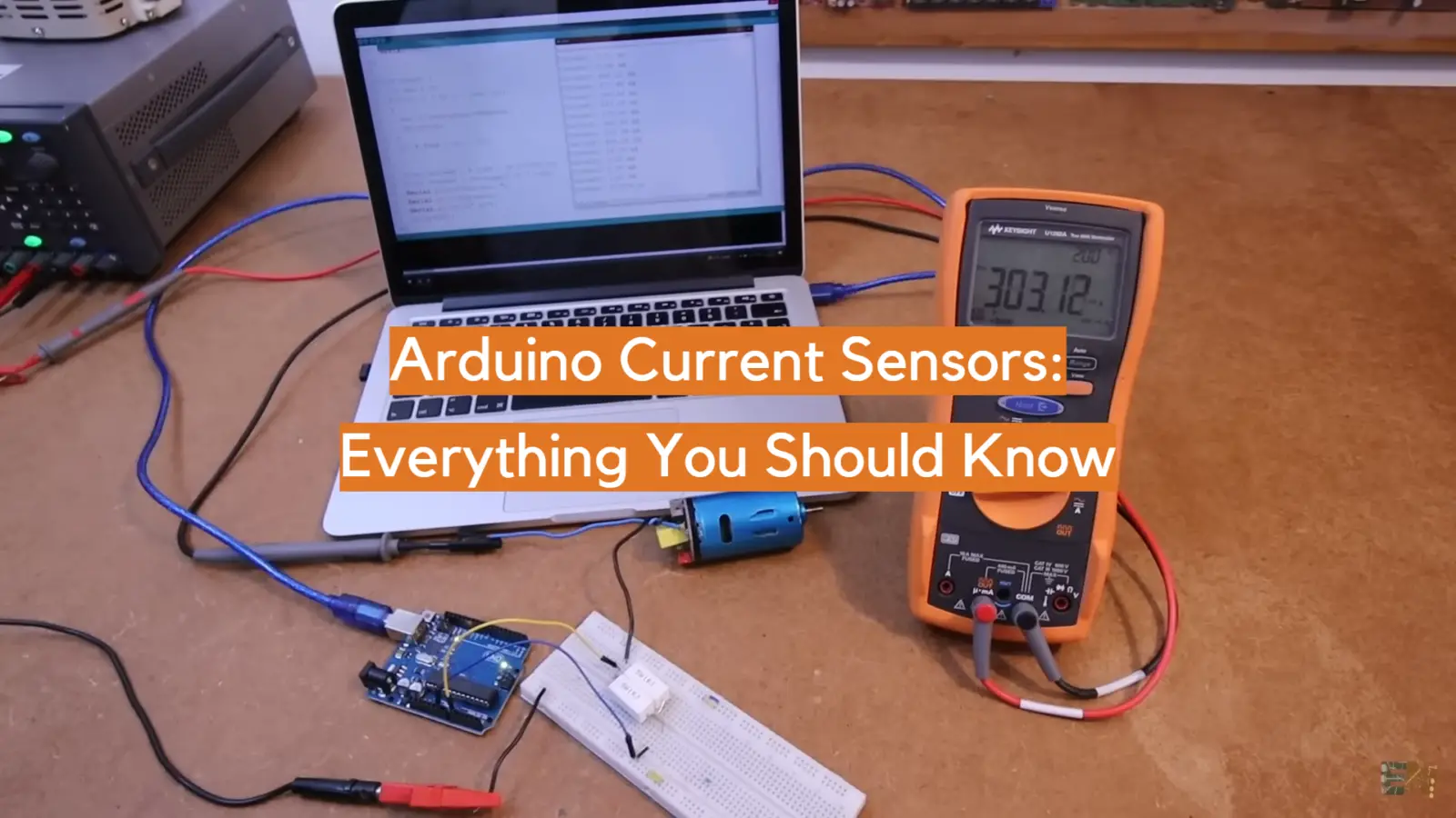
For the novice inventor, getting started with Arduino Current Sensors can seem like a daunting task. But it’s really not as complicated as it seems! With a little know-how and some basic components, you can quickly and easily begin to take advantage of this powerful technology. This blog post will look at what Arduino Current Sensors are, why they’re important, and the components you need to get started using them for your projects. So, don’t be intimidated – dive into the world of Arduino Current Sensors!
What are Arduino Current Sensors?

When using an Arduino current sensor, it’s important to choose one that has the correct range for your application. Generally speaking, the higher the current range of the sensor, the more accurate it will be. Additionally, some sensors have features such as built-in calibration and protection against overloads or shorts. Depending on your project’s requirements, you may want to purchase a specialized sensor with these additional features.
Finally, wiring up your Arduino current sensor is a fairly straightforward process. The output signal from most current sensors needs to be connected directly to an analog pin on your microcontroller board. Once this connection is established, you can easily program your board to read values from the sensor and display them accordingly. You can then use those readings for various applications such as monitoring energy consumption or controlling motors in real time. With careful selection and proper wiring, Arduino current sensors are a great way to expand your project’s capabilities [1].
What are the Advantages of Using an Arduino Current Sensor?
Using an Arduino current sensor offers several advantages for both novice and experienced makers alike. The most obvious advantage is that it allows you to monitor and measure current in real-time, allowing for more efficient designs or applications.
Current sensors also protect against overloads and shorts which can come in handy if you’re working with high-voltage systems. Additionally, they make wiring and setup easier since all you need to do is connect the output from the sensor to an analog pin on your microcontroller board. Finally, most current sensors are relatively inexpensive compared to other specialized sensors for measuring current. All in all, they’re an excellent tool for any Arduino maker!
Another great advantage of using a current sensor with your Arduino is the ability to measure AC or DC voltage. With a basic understanding of Ohm’s law, you can calculate things like power output and efficiency using the measured values from your current sensor. This gives makers further insight into their designs and allows them to more accurately diagnose problems or optimize performance.
Furthermore, users don’t need to worry about additional components such as resistors since most current sensors come with built-in protection mechanisms to prevent overloads or shorts. Finally, there are plenty of tutorials online which can help get you started working with current sensors on your Arduino project quickly and easily.
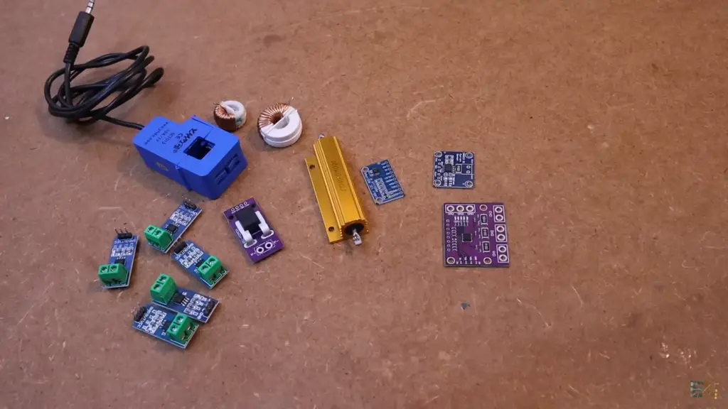
Arduino Current Sensor Methods
Voltage drop Arduino Current Sensors
This method uses a voltage drop across a resistor to measure current. The resistance value of the resistor is fixed and the current flowing through it creates a proportional voltage drop which you can measure with your Arduino. This requires an additional circuit but gives you quite accurate results and works well in situations up to about 1A or so.
Hall Effect Current Sensor Arduino Method
If you need to measure higher currents than what is possible with the voltage-drop method, then this technique is the best choice. A Hall effect sensor can be used to accurately detect current flow by measuring its magnetic field when placed around a wire carrying current. The output from such sensors can be read directly into your Arduino board using an analog input pin. The advantage of this method is that it can be used with much higher currents (up to 100A) and requires no additional circuit.
AC/DC Current Sensor Arduino Method
For measuring AC as well as DC, an AC/DC sensor can be used. These sensors are available in both isolated and non-isolated versions. Isolated versions provide galvanic isolation from the high voltages present in your system while non-isolated versions are easier to use but require more caution. They measure current by sensing a magnetic field created by the flow of current through them and output a proportional voltage which you can read into your Arduino board using an analog input pin [2].
Components Needed To Build Arduino ACS712 Sensor Project
Hardware Components
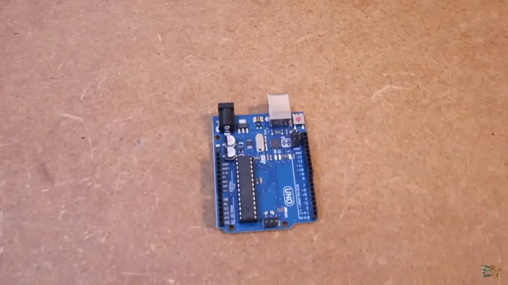
- Arduino Uno Board
- ACS712 Current Sensor Module
- 10k Resistor
- Power Supply (5V)
- Wires and Connectors
Software Components:
- Arduino IDE
- Computer or Laptop with USB port
Once you have all the hardware components, it’s time to get started on building the project. The first step is to upload a sketch into the Arduino board. To do this, you will need to download the Arduino IDE software from the official website. Once this is installed, connect your board via USB cable and open up the program. Now select the appropriate board type from “Tools/Board Type” and click on “File/Open” and select the code file. After that, click on “Sketch/Upload” to upload the program onto the board.
Once the sketch is uploaded, it’s time to assemble your hardware components. Start by connecting all the wires from your power supply to your Arduino board. The red wire should connect to the VIN of the board, while the black one should go into GND. Then you can attach your current sensor module and resistor as shown in the diagram above. Finally, connect a USB cable between your computer or laptop and Arduino board for programming purposes.
Basics of The ACS712 Current Sensor
Pin-out diagram of ACS712 IC
The ACS712 Current Sensor is an integrated circuit that has five pins: VCC, GND, OUT, A1 and A2.
VCC – This pin supplies the operating voltage for the IC. It should be connected to a 5V or 3.3V power supply source depending on the version of the IC used.
GND – This pin connects to ground potential.
OUT– Output pin can either provide an analog output voltage (in mV) corresponding to the sensed current or digital pulse-width modulation (PWM) output signals depending on how it is configured using A1 and A2 pins.
A1 and A2– These two pins are used for configuring the device into different operating modes.
Working of ACS712 IC
The ACS712 IC is used for measuring both AC as well as DC currents. It works on the principle of Hall Effect, which states that when a magnetic field is applied perpendicular to a current-carrying conductor, then the voltage will be generated across the conductor due to its Lorentz force. This voltage can be measured using a hall effect sensor and then converted into an equivalent current value by calibration. The output of this IC is in mV/A and it can measure up to 5A, 20A or 30A depending upon the version chosen.
Electrical specifications of ACS712 IC
The ACS712 ICs can operate from 2.3V to 5.5V and have a typical bandwidth of 20kHz, so the current sensing resolution is quite good even at low currents (down to 50mA). The operating temperature range is from -40°C to +125°C. It has an input offset voltage of 1.6mV, output noise of 0.1% FS, pull-up resistor value of 10kΩ, and a maximum quiescent current of 250uA which makes it power efficient.
Applications
The ACS712 Current Sensor is mainly used for motor control applications such as brushless DC motors or stepper motors, lighting control systems, battery protection circuits, and many other industrial applications. It is also used in automotive systems for monitoring the current draw of engines and other components. Its small size, low power consumption, and high accuracy make it a perfect choice for such applications.
Step-By-Step Instructions To Connect The Current Sensor ACS712 With Arduino UNO
- Gather all the required components: Arduino UNO board, ACS712 Current Sensor, jumper wires, and a breadboard.
- Connect the VCC pin of the current sensor to the 5V pin on the Arduino UNO board using a jumper wire.
- Connect the GND pin of the current sensor to one of the ground pins on the Arduino UNO board using a jumper wire.
- Connect an output pin on your Arduino to signal line (S) on your ACS712 sensor with a jumper wire and then connect it to your breadboard, making sure that all pins are properly connected in their respective locations.
- Plug in your power source (either a 9V battery or a 9V DC adapter) to the Arduino UNO board.
- Open up your Arduino IDE and upload the ACS712 library sketches from the examples section for testing purposes.
- After successfully uploading your code, open up your Serial Monitor to start reading the current values being outputted by your sensor regularly.
- You can now use this data in other applications such as logging data or controlling devices like motors or lights based on the readings from your current sensor [3]!
Arduino Code Example For The ACS712 Current Sensor Project
The complete Arduino code for the 5 A version
The complete Arduino code for the 5 A version of the ACS712 is shown below:
// include library for the sensor
#include
// Define pins for each side of the circuit
const int pinA = A5; //input pin connecting to AC current sense transformer
const int pinV = A3; //input pin connecting to ground of DC power supply
const int ledPin = 9; // output LED pin
float calibrationFactor = 0.185; //calibration factor used in formula (0.185 for 5A version)
ACS712 acs(pinA, pinV); // create acs object with input and output pins as parameters
void setup() {
pinMode(ledPin, OUTPUT); //configure LED pin as output
}
void loop() {
int currentReading = acs.readRaw(); // read raw sensor value
float currentVoltage = ((float)currentReading / 1024) * 5; //convert reading to voltage
float actualCurrent = (currentVoltage – 2.5) / calibrationFactor; // use formula to get actual AC current
if (actualCurrent < 0.5){ //if the current is less than 0.50 A, turn on LEDs
digitalWrite(ledPin, HIGH);
} else{ //otherwise turn off LEDs
digitalWrite(ledPin, LOW);
}
delay(1000); // wait for 1 second
}
The code above is written using the Arduino IDE. The ACS712 library should be installed before running this code. To install the library, follow the instructions outlined in the getting started section of this tutorial. After uploading the code to your board, you can monitor its output on an oscilloscope or multimeter and make sure that it is working as expected. You can also use a serial monitor if you need more detailed readings about what’s happening inside your circuit.
The complete Arduino code for the 20 A version
The complete Arduino code for the 20 A version of the ACS712 is shown below:
// include library for the sensor
#include
// Define pins for each side of the circuit
const int pinA = A5; //input pin connecting to AC current sense transformer
const int pinV = A3; //input pin connecting to ground of DC power supply
const int ledPin = 9; // output LED pin
float calibrationFactor = 0.100; //calibration factor used in formula (0.100 for 20A version)
ACS712 acs(pinA, pinV); // create acs object with input and output pins as parameters
void setup() {
pinMode(ledPin, OUTPUT); //configure LED pin as output
}
void loop() {
int currentReading = acs.readRaw(); // read raw sensor value
float currentVoltage = ((float)currentReading / 1024) * 5; //convert reading to voltage
float actualCurrent = (currentVoltage – 2.5) / calibrationFactor; // use formula to get actual AC current
if (actualCurrent < 0.5){ //if the current is less than 0.50 A, turn on LEDs
digitalWrite(ledPin, HIGH);
} else{ //otherwise turn off LEDs
digitalWrite(ledPin, LOW);
}
delay(1000); // wait for 1 second
}
FAQ
Which current sensor is used in Arduino?
The most commonly used current sensor in Arduino is the Allegro ACS712. This device uses a Hall effect technology to measure both AC and DC currents up to 30A. It is small, inexpensive, and easy to hook up with an Arduino board or other microcontrollers. Other current sensors such as the INA169 are also available, but they tend to be more expensive and less flexible than the ACS712.
How do I connect my current sensor to my Arduino?
First, you will need your power source (battery or plug-in adapter), current sensor, and Arduino board. The Allegro ACS712 has four pins labeled VCC (power), GND (ground), OUT (output), and CS (current sense). Connect the VCC and GND pins to your power source, connect OUT to an analog input pin on your Arduino board, and connect CS to one of the ground (GND) pins. Once everything is connected you can then use the Arduino IDE or other programming language to access the analog input values.
What type of power supply should I use with my current sensor?
It is recommended that you use a regulated power supply when using a current sensor such as the Allegro ACS712. This ensures that the voltage level remains constant and does not fluctuate, which could affect its accuracy. You can also use batteries but it is important to make sure they are in good condition and provide sufficient voltage for your sensors.
Which DC current sensor is best for Arduino?
The Allegro ACS712 is the most popular DC current sensor for Arduino. It is small, inexpensive, and easy to connect with an Arduino board or other microcontrollers. Its accuracy ranges from 0.1A up to 30A, making it suitable for a variety of applications. Other sensors such as the INA169 are also available but tend to be more expensive and less flexible than the ACS712.
Can I use an AC current sensor with Arduino?
Yes, AC current sensors can be used with Arduino boards or other microcontrollers. The Allegro ACS712 is one example of an AC current sensor that can be used with Arduino and has a range of 0-5VAC (50/60Hz) input. It is important to note that AC current sensors can be more difficult to connect and use than DC current sensors, so make sure you understand the requirements before getting started.
Can I measure both AC and DC currents with the same sensor?
Yes, some current sensors such as the Allegro ACS712 are capable of measuring both AC and DC currents. This makes them very versatile and convenient for various applications. However, it is important to check the specifications of your sensor to ensure it has the necessary range to accurately measure both types of currents.
Useful Video: Different Ways for Measuring Current With Arduino
Conclusion Paragraph
Arduino current sensors are a great tool for measuring and monitoring the amount of current flowing through electrical circuits. They can be used to detect faults in wiring, measure levels of power usage for devices, or even provide real-time data about electricity consumption. The Arduino platform is highly compatible with various current sensors, making it easy to integrate them into projects. With its wide range of capabilities and availability, it is no surprise that Arduino’s current sensors are becoming increasingly popular among makers and DIYers alike.
References
- https://www.electronicshub.org/interfacing-acs712-current-sensor-with-arduino/#
- https://www.best-microcontroller-projects.com/arduino-current-sensor.html
- https://www.makerguides.com/acs712-current-sensor-and-arduino-a-complete-guide/