In electrical circuits, capacitors play a vital role in storing and releasing electrical energy. Understanding the behavior of capacitors is crucial for designing and analyzing electronic systems. One important aspect of capacitor behavior is the peak voltage across it.
In this article, we will explore the concept of peak voltage and specifically focus on the peak voltage across a 4.0 μF capacitor. We will delve into the factors that influence the peak voltage, the equations involved in its calculation, and the significance of this value in circuit design and analysis.
By the end, you will have a comprehensive understanding of the peak voltage across a 4.0 μF capacitor and its implications in practical applications.
What Is the Peak Voltage Across the Capacitor?
A capacitor consists of two conductive plates separated by an insulating material known as a dielectric. When a voltage source is connected across the plates, the capacitor begins to charge, storing energy in the electric field between the plates [1].
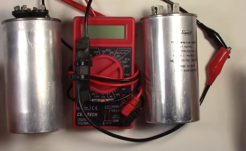
During the charging phase of a capacitor, the voltage across it gradually increases. However, the peak voltage refers to the maximum voltage attained during this charging process. As the capacitor charges, the voltage across its plates rises until it reaches the peak voltage, at which point the charging process stops.
Several factors influence the peak voltage across a capacitor. The capacitance value of the capacitor determines how much charge it can store for a given voltage. Higher capacitance values result in a higher peak voltage. Additionally, the voltage applied to the capacitor affects the peak voltage. A higher applied voltage leads to a higher peak voltage.
Understanding the peak voltage across a capacitor is essential for designing circuits and selecting appropriate components. Engineers and circuit designers must consider the peak voltage to ensure that the capacitors used can handle the maximum voltage without exceeding their voltage ratings.
Furthermore, knowledge of the peak voltage assists in determining the power dissipation across the capacitor. By multiplying the peak voltage by the charge stored, one can calculate the energy dissipated as heat in the capacitor. This information aids in selecting capacitors with suitable power handling capabilities, preventing overheating and potential damage.
What Is the Peak Current in Capacitor?
When charging a capacitor, current flows from the source to the capacitor until the capacitor is fully charged, at which point the current ceases. However, during the initial stages of charging, the current is at its peak, and this peak current can have important implications for the performance and lifetime of the capacitor.
The peak current in a capacitor is the maximum current that flows from the source to the capacitor during the charging process. This current can be quite high, especially for high-capacitance capacitors or capacitors that are charged with high-voltage sources. The peak current can be calculated using the formula I = C * (ΔV/Δt), where I is the peak current, C is the capacitance, ΔV is the change in voltage, and Δt is the time over which the voltage changes [2].
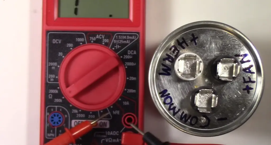
The peak current is important because it can cause various issues with the capacitor and the circuit in which it is used. For one, the high current can cause electromagnetic interference (EMI) that can interfere with nearby electronic components. It can also cause thermal stress, where the heating from the high current can lead to material fatigue and eventual failure of the capacitor.
The peak current can also be important when selecting a capacitor for a specific application. If the circuit requires a high peak current, then a capacitor with a higher rated current should be used. In contrast, if the circuit requires a lower peak current, then a lower rated capacitor could be selected. Capacitors with higher peak current ratings tend to be more expensive, so it is important to balance the performance requirements with the cost.
In some cases, the peak current can be mitigated through the use of inrush current limiting circuits or soft start circuits. These circuits can limit the initial current flow to the capacitor, reducing the EMI and thermal stress. However, these circuits can add complexity and cost to the overall system.
How Much Voltage Does a Capacitor Release?
When a capacitor discharges, the voltage it releases depends on several factors, including the initial voltage across the capacitor and the load connected to it. To understand how much voltage a capacitor releases, let’s explore the process of discharging and the factors that influence it.
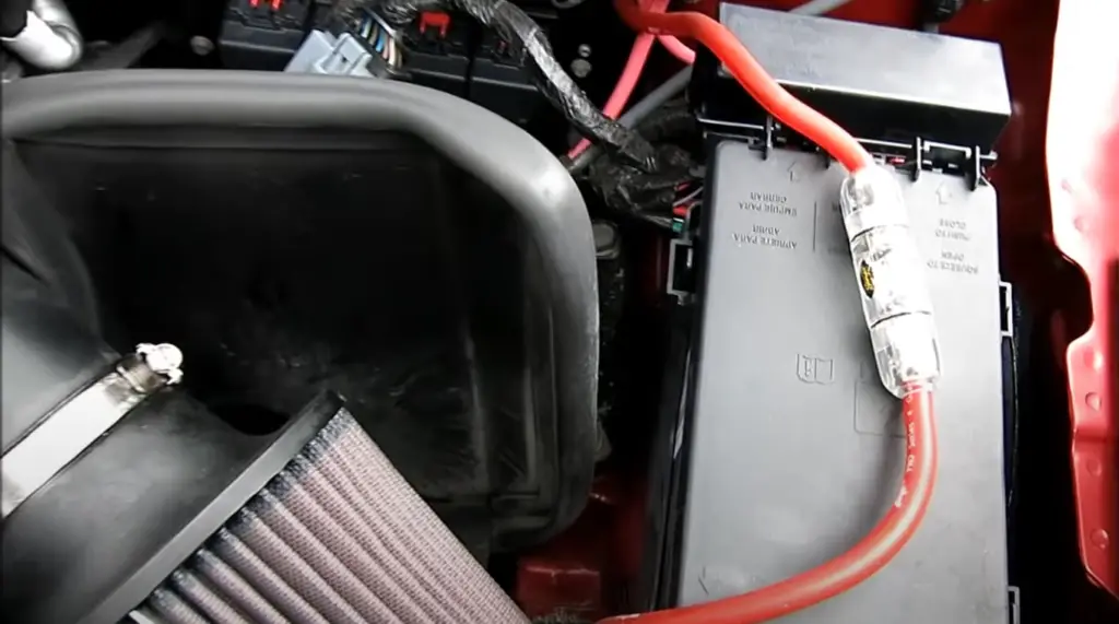
Discharging Process
When a charged capacitor is connected to a load or a circuit, the stored energy in the capacitor is released. The discharging process begins, and the voltage across the capacitor gradually decreases over time. The rate at which the voltage decreases follows an exponential decay curve, governed by the time constant of the circuit.
Factors Affecting Discharged Voltage:
- Initial Voltage: The voltage across the capacitor at the start of the discharge process determines the maximum voltage it can release. A capacitor charged to a higher voltage will have a higher potential for releasing more voltage during the discharge;
- Capacitance Value: The capacitance value of the capacitor plays a crucial role in determining the amount of charge it can store and subsequently release. A capacitor with a higher capacitance value can store more charge and, therefore, has the potential to release a higher voltage during discharge;
- Load Resistance: The load resistance connected to the capacitor during discharge affects the rate of voltage decay. A higher load resistance slows down the discharge process, resulting in a slower decrease in voltage over time. Conversely, a lower load resistance allows for a faster discharge, leading to a more rapid decrease in voltage
- Time Constant: The time constant of the circuit, determined by the product of the capacitance and the load resistance, influences the rate of voltage decay during discharge. A larger time constant leads to a slower voltage decay, while a smaller time constant results in a faster voltage decay;
Why Can’t the Voltage Across a Capacitor Change Instantaneously?
To understand why voltage cannot change instantaneously across a capacitor, it is helpful to consider how a capacitor works. A capacitor consists of two conducting plates that are separated by a dielectric material, such as air or plastic. When a voltage is applied to the capacitor, electrical charge is stored on the plates, creating an electric field between them.
The charge on the plates and the electric field between them determine the voltage across the capacitor. If the voltage across the capacitor were to change instantaneously, this would require the charge on the plates to change instantaneously as well. However, in reality, the charge cannot change instantaneously because it takes time for the charge to flow through the circuit.
In particular, the flow of charge depends on the resistance of the circuit and the capacitance of the capacitor. The capacitance of a capacitor is a measure of its ability to store charge, while the resistance of the circuit is a measure of the degree to which it opposes the flow of charge. Because of these properties, capacitors cannot change voltage instantaneously.
Another way to think about this is to consider the mathematical relationship between voltage and current in a capacitor. Specifically, the current through a capacitor is proportional to the rate of change of voltage across it. If the voltage were to change instantaneously, the rate of change of voltage would be infinite, resulting in an infinite current through the capacitor. However, this is not physically possible, as it would require an infinite amount of charge in zero time.
How Do Capacitors Release Charge?
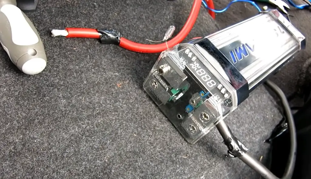
Capacitors release charge when the circuit they are a part of allows current to flow between their plates, thus creating a path for the stored charges to neutralize. When a capacitor is charged, electrical charge builds up on the plates, creating an electric field between them.
However, if a path for current to flow through is created in the circuit, the charge will flow out of the capacitor, causing it to discharge.
The rate of discharge depends on the capacitance of the capacitor and the resistance of the circuit. Larger capacitors can store more charge and take longer to discharge, while smaller capacitors release their charge more quickly.
Additionally, the discharge of a capacitor can be accompanied by a spark or a loud noise, especially if the capacitor has a high voltage or energy stored in it.
What Is the Peak Voltage Across the 4.0μF Capacitor?
In a basic circuit configuration with a single capacitor and a voltage source, the peak voltage across the capacitor depends on the voltage of the source and the time it takes to charge the capacitor. The formula to calculate the voltage across a capacitor during charging is given by:
Vc(t) = V0 * (1 – e^(-t/RC))
Where:
- Vc(t) represents the voltage across the capacitor at a given time;
- V0 is the initial voltage across the capacitor (voltage source);
- e is the mathematical constant approximately equal to 2.71828;
- t is the time elapsed since the start of charging;
- R is the resistance in the circuit (if present);
- C is the capacitance of the capacitor [3];
To find the peak voltage, you also need to know the charging time and the characteristics of the voltage source. With this information, you can determine the time at which the voltage across the capacitor reaches its maximum value.
Once you have the maximum time (t_max), we substitute it into the formula to calculate the peak voltage. It’s worth noting that in an ideal scenario without any resistance or other circuit components, the peak voltage would be equal to the voltage of the source.
What Is the Voltage Across a 6μF Capacitor?
When charging a capacitor in a simple circuit configuration with a voltage source, the voltage across the capacitor increases over time until it reaches the voltage of the source. The relationship between the voltage across the capacitor (Vc) and time (t) during charging is given by the equation:
Vc(t) = V0 * (1 – e^(-t/RC))
Where:
- Vc(t) represents the voltage across the capacitor at a given time;
- V0 is the initial voltage across the capacitor (voltage source);
- e is the mathematical constant approximately equal to 2.71828;
- t is the time elapsed since the start of charging;
- R is the resistance in the circuit (if present);
- C is the capacitance of the capacitor;
Discharging a Capacitor
When discharging a capacitor, the voltage across the capacitor decreases over time. The relationship between the voltage across the capacitor (Vc) and time (t) during discharging is given by the equation:
Vc(t) = V0 * e^(-t/RC)
Where the variables have the same meaning as in the charging equation.
To calculate the voltage across a 6μF capacitor, you would need to know the specifics of the circuit and the conditions under which the capacitor is being charged or discharged. This includes information such as the voltage source characteristics, the presence of any resistors in the circuit, and the time elapsed since the start of charging or discharging.
Once you have the necessary information, you can substitute the values into the appropriate equation to calculate the voltage across the capacitor at a specific time or determine the final voltage after the charging or discharging process is complete.
FAQ:
1. How do you find the peak voltage across a capacitor?
The peak voltage across a capacitor can be found by analyzing the circuit configuration and the charging or discharging process. To determine the peak voltage, you need to calculate the voltage at the specific time when the voltage across the capacitor reaches its maximum value. This can be done by using the relevant equations that describe the charging or discharging behavior of the capacitor, considering factors such as the capacitance, resistance, time constant, and initial voltage.
2. What is the voltage across a 4.5 µF capacitor if the charge on one plate is 0.12 C? How much energy is stored?
To calculate the voltage across a capacitor when the charge on one plate is known, you can use the formula Q = CV, where Q is the charge, C is the capacitance, and V is the voltage. Rearranging the formula, V = Q/C, you can substitute the given values to find the voltage.
As for the energy stored in the capacitor, it can be calculated using the formula E = 0.5 * C * V^2, where E is the energy, C is the capacitance, and V is the voltage. By substituting the values into the equation, you can find the amount of energy stored.
3. How do you calculate the peak voltage?
To calculate the peak voltage across a capacitor, you need to analyze the circuit and determine the time when the voltage reaches its maximum value. This involves using the relevant equations that describe the charging or discharging process of the capacitor. The peak voltage typically occurs when the capacitor is fully charged or fully discharged. The specific calculation depends on the circuit configuration, the initial voltage, the capacitance, and any other components present in the circuit.
4. What is the peak voltage of 480 V?
The peak voltage of a 480 V source is equal to the magnitude of the voltage itself. In an alternating current (AC) system, the peak voltage refers to the maximum positive or negative value reached by the voltage waveform. Therefore, the peak voltage of a 480 V source would be 480 V.
5. How much charge is on each plate of a 4.00 µF capacitor?
To determine the charge on each plate of a capacitor, you need to know the voltage across the capacitor and the capacitance value. The formula for calculating the charge is Q = CV, where Q is the charge, C is the capacitance, and V is the voltage. By substituting the given values, you can calculate the charge on each plate of the 4.00 µF capacitor.
6. What is the voltage across a 1 µF capacitor?
The voltage across a capacitor depends on the circuit configuration, the charging or discharging process, and the voltage source characteristics.
7. What is the voltage across a 3 µF capacitor?
Similar to the previous question, the voltage across a 3 µF capacitor depends on the circuit configuration, the charging or discharging process, and the voltage source characteristics. Without additional information, it is not possible to determine the voltage across a 3 µF capacitor.
8. What is the voltage across the 20 µF capacitor?
To determine the voltage across a 20 µF capacitor, you need additional information such as the circuit configuration and the charging or discharging conditions. Without these details, it is not possible to provide an exact value for the voltage across a 20 µF capacitor.
9. When 4 volts emf is applied across a 1 farad capacitor?
When a 4-volt electromotive force (emf) is applied across a 1 farad capacitor, the voltage across the capacitor will be equal to the applied voltage. In this case, the voltage across the capacitor would be 4 volts.
10. What is the value of capacitance of a capacitor which has a voltage of 4 V and has 16 C of charge?
To find the capacitance value of a capacitor, you can use the formula C = Q/V, where C is the capacitance, Q is the charge, and V is the voltage. By substituting the given values, you can calculate the capacitance of the capacitor.
11. What is the voltage of a 10 µF capacitor?
The voltage of a capacitor depends on the circuit configuration and the conditions under which the capacitor is being charged or discharged. Without additional information, it is not possible to determine the voltage of a 10 µF capacitor.
12. What is the charge on the 1.5 µF capacitor?
To determine the charge on a capacitor, you need to know the capacitance value and the voltage across the capacitor. The charge can be calculated using the formula Q = CV, where Q is the charge, C is the capacitance, and V is the voltage. Without the voltage information, it is not possible to determine the charge on the 1.5 µF capacitor.
13. What is the potential difference across the 4.5 µF capacitor shown in the figure?
To determine the potential difference (voltage) across a capacitor shown in a figure, the figure itself or a description of the circuit configuration is necessary. Without this information, it is not possible to provide the specific potential difference across the 4.5 µF capacitor.
14. What is the voltage rating of a 2.2 µF capacitor?
The voltage rating of a capacitor refers to the maximum voltage it can safely withstand without experiencing failure or damage. To determine the voltage rating of a 2.2 µF capacitor, you need to consult the manufacturer’s specifications or markings on the capacitor itself. The voltage rating is typically indicated on the capacitor and can vary depending on the specific model or type.
Useful Video: Capacitors Explained – The basics how capacitors work working principle
References
- https://www.electronicstalk.org/what-is-the-peak-voltage-across-the-4-0%CE%BCf-capacitor/
- https://homework.study.com/explanation/what-is-the-peak-voltage-across-a-4-0-u-f-capacitor.html
- https://en.wikipedia.org/wiki/Capacitor








Leave a Reply