Printed Circuit Boards (PCBs) are essential components in modern electronic devices and machines. The PCB substrate, which is the base material of the PCB, plays a crucial role in determining the board’s performance, reliability, and cost. There are several types of PCB substrates available in the market, and each has its unique characteristics, advantages, and disadvantages. The choice of PCB substrate type depends on several factors, such as the application, the desired performance, and the budget.
This article aims to provide a comprehensive guide to the different types of PCB substrates available in the market, their characteristics, and their applications.
The article begins by defining the basic properties of a PCB substrate, such as dielectric constant, thermal conductivity, and coefficient of thermal expansion. It then delves into the different types of PCB substrates, such as FR4, Rogers, and ceramic substrates, providing a detailed description of their properties, advantages, and limitations.
What is a PCB Substrate?
The substrate is typically made of a non-conductive material, such as fiberglass, paper, or ceramic, and provides a sturdy platform for the conductive traces and components that make up the PCB. The substrate material is also responsible for providing insulation and supporting the electronic components of the circuit [1].
The choice of PCB substrate material is critical to the overall performance, reliability, and cost of the PCB. Different substrate materials offer different electrical, mechanical, and thermal properties, which must be considered when designing a PCB.
For example, some materials may have better thermal conductivity, making them suitable for high-power applications, while others may have better dielectric properties, making them suitable for high-frequency applications.
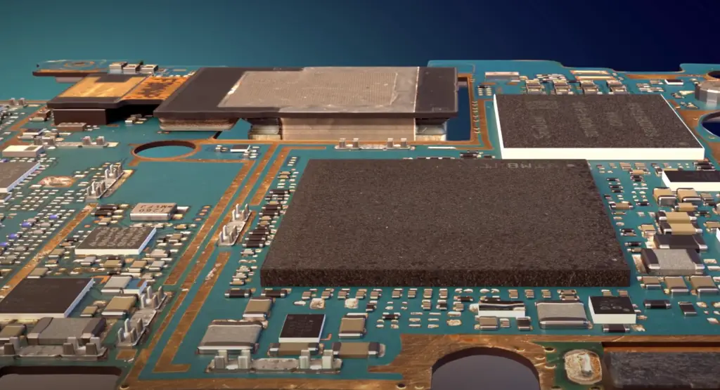
The thickness and dielectric constant of the substrate material can also affect the electrical properties of the circuit, such as impedance and signal loss. Therefore, the choice of substrate material is an important consideration for PCB designers, who must balance the electrical and mechanical requirements of the circuit with the cost and availability of the substrate material.
How are PCB Substrates Made?
PCB substrates are typically made through a process called lamination. The process begins with a base material, which can be made from a variety of materials, including fiberglass, paper, or ceramic. The base material is then coated with a layer of copper on both sides using a process called electroless plating.
Next, a photoresist layer is applied to the copper layer, and a pattern of the desired circuit is printed onto the photoresist using a photolithography process. The photoresist is then developed, leaving behind the pattern of the circuit on the copper layer. The exposed copper is then etched away using an acidic solution, leaving only the desired circuit pattern.
After the circuit is etched, the remaining photoresist is removed, and the board is rinsed and dried. The board is then laminated with a layer of substrate material, which is typically made from fiberglass cloth impregnated with an epoxy resin. The layers of substrate and copper are then pressed together under high heat and pressure, causing the resin to cure and bond the layers together [2].
This process is repeated for each layer of the PCB until the desired number of layers is achieved. Once the layers are laminated together, the holes for components and vias are drilled into the board, and the board is plated with a layer of copper to form electrical connections between the layers.
Finally, the board is coated with a layer of solder mask, which protects the copper traces from oxidation and makes it easier to solder components onto the board. Silkscreen is then applied to label the components and provide other necessary information.
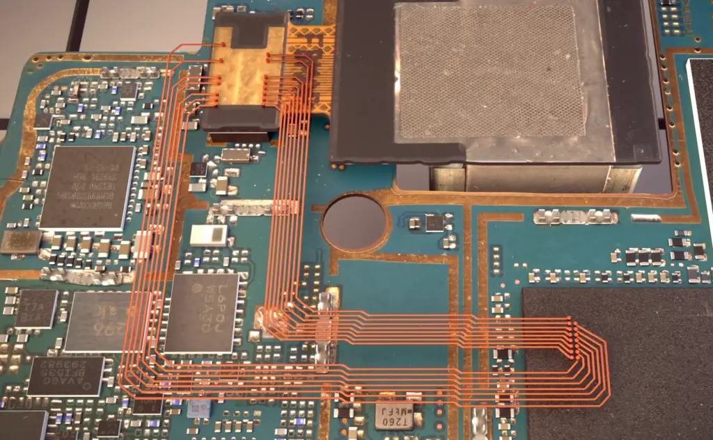
Different Types of PCB Substrates Mean Different Results
Printed Circuit Boards (PCBs) are an essential component of electronic devices and come in various types, each with its own unique properties and advantages. The substrate material used in a PCB plays a critical role in determining the overall performance and reliability of the device. PCB substrate materials can be broadly categorized into three types: ceramic, paper, and fiberglass.
Ceramic PCBs are made from high-temperature fired ceramics and offer excellent thermal conductivity and stability, making them suitable for high-power applications. They are also highly durable and resistant to moisture and chemicals, making them ideal for harsh environments. However, ceramic PCBs are expensive to produce and are less common than other substrate types [3].
Paper PCBs were the first type of substrate material used in early PCBs and are still used in some low-cost applications. They are made from paper reinforced with phenolic resin and offer low cost and good mechanical strength but are not suitable for high-frequency applications due to their high dielectric loss.
Fiberglass PCBs, also known as FR4 PCBs, are the most common type of PCB substrate. They are made from woven fiberglass cloth impregnated with an epoxy resin, offering good mechanical strength, electrical insulation, and low cost. They can be used for a wide range of applications and are suitable for both low and high-frequency applications.
Within the category of fiberglass PCBs, there are several subtypes that offer different performance characteristics. FR1 and FR2 PCBs have lower mechanical strength and higher dielectric loss than FR4 PCBs, making them suitable for low-cost applications. FR4 high-Tg PCBs offer higher glass transition temperatures than standard FR4, making them suitable for high-temperature applications.
PCB Substrates: All Major Properties of Dielectric Material
1) Thermal Properties:
Glass Transition Temperature
This is important because as the temperature of the PCB increases, the substrate material may become more pliable, which can affect the PCB’s mechanical and electrical properties. A substrate material with a higher Tg is typically preferred for high-temperature applications, as it can withstand higher temperatures without losing its rigidity.
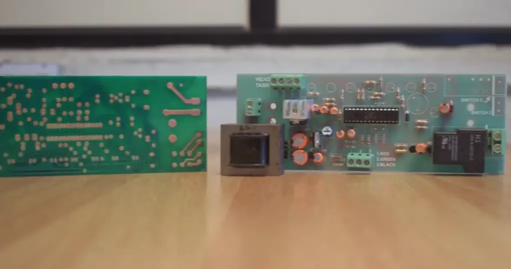
Decomposition Temperature
The decomposition temperature (Td) is the temperature at which a PCB substrate material begins to break down and decompose. This can result in the release of gases or other materials that can affect the performance of the PCB. A substrate material with a higher Td is preferred, as it can withstand higher temperatures without breaking down or releasing gases that could damage the board [4].
Coefficient of Thermal Expansion
The coefficient of thermal expansion (CTE) is a measure of how much a material expands or contracts when subjected to changes in temperature. This property is important for PCB substrate materials because the expansion or contraction of the material can cause stress and strain on the PCB, potentially leading to cracks or other damage. A substrate material with a lower CTE is preferred, as it will expand and contract less when subjected to temperature changes.
Thermal Conductivity
Thermal conductivity is the ability of a material to transfer heat. This property is important for PCB substrate materials because it affects the material’s ability to dissipate heat generated by components on the PCB. A substrate material with higher thermal conductivity is preferred, as it can help to dissipate heat more effectively, preventing components from overheating and potentially failing.
2) Electrical Properties:
Relative Permittivity or Dielectric Constant (Dk or Er)
The relative permittivity, also known as the dielectric constant (Dk or Er), is a measure of a material’s ability to store electrical charge. It affects the capacitance and propagation velocity of the signal in the PCB. A higher relative permittivity can result in higher capacitance and slower signal propagation, which can affect the performance of high-speed digital and RF circuits. Therefore, selecting a substrate material with a lower Dk is preferred for high-speed and RF applications.
Dissipation Factor or Dielectric Loss Tangent (Df Tan δ)
The dissipation factor or dielectric loss tangent (Df Tan δ) is a measure of a material’s ability to absorb electrical energy and convert it into heat. It affects the signal loss and distortion in the PCB. A higher Df Tan δ can result in higher signal loss and distortion, which can affect the performance of high-frequency and high-speed circuits. Therefore, selecting a substrate material with a lower Df Tan δ is preferred for high-frequency and high-speed applications.
Volume Resistivity
Volume resistivity is a measure of a material’s ability to resist the flow of electrical current through its volume. It affects the leakage current and insulation resistance of the PCB. A higher volume resistivity can result in lower leakage current and higher insulation resistance, which are desirable properties for reliable and long-lasting PCBs.
Surface Resistivity (ρS)
Surface resistivity (ρS) is a measure of a material’s ability to resist the flow of electrical current across its surface. It affects the electrostatic discharge (ESD) protection of the PCB. A higher surface resistivity can result in better ESD protection and a lower risk of damage to the components.
Electrical Strength
Electrical strength is a measure of a material’s ability to withstand electrical stress without breaking down. It affects the insulation properties of the PCB. Higher electrical strength is preferred for reliable and long-lasting PCBs, as it can prevent electrical breakdown and damage to the board.
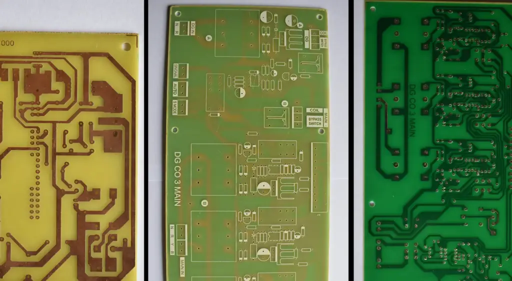
3) Chemical Properties
Chemical properties are also important to consider when choosing a PCB substrate material, as they can affect the overall durability and reliability of the board. Some important chemical properties include:
- Flammability Specs – UL94: This is a measure of a material’s resistance to burning. The Underwriters Laboratories (UL) 94 standard rates materials on a scale from V-0 to V-2, with V-0, indicating the highest level of flame retardancy;
- Moisture Absorption: PCBs can be exposed to a range of environmental conditions, including high humidity, which can cause moisture to be absorbed into the board. Moisture absorption can affect the electrical properties of the board and cause delamination or cracking;
- Methylene Chloride Resistance: This is a measure of a material’s resistance to chemicals. Methylene chloride is commonly used in the PCB manufacturing process, so it’s important to choose a substrate material that is resistant to this chemical;
4) Mechanical Properties
Mechanical properties are also important to consider when selecting a PCB substrate material. The mechanical properties of a material can affect its strength, durability, and resistance to damage during the manufacturing process and in the field.
Some important mechanical properties to consider include:
- Peel Strength: This is a measure of the bond strength between the substrate and the copper foil. High peel strength is important to ensure the copper remains securely bonded to the substrate over time.
- Flexural Strength: This is a measure of a material’s resistance to bending or breaking. High flexural strength is important to ensure the board can withstand stresses during the manufacturing process and in use.
- Young’s Modulus: This is a measure of a material’s stiffness or resistance to deformation under stress. A high Young’s modulus is important to ensure the board retains its shape and does not deform during use.
- Density: This is a measure of a material’s mass per unit volume. A higher density can indicate a more durable and rigid material.
- Time to Delamination: This is the amount of time it takes for the substrate and copper layers to separate or delaminate. A longer time for delamination is desirable to ensure the board remains intact during use [5].
When selecting a PCB substrate material, it is important to consider all of these mechanical properties and how they will affect the performance and reliability of the board. Depending on the application, certain properties may be more important than others, so it’s important to choose a material that meets the specific requirements of the project.
Main Types Of PCB Substrate:
FR-2
FR-2 is a type of paper-based phenolic substrate that is widely used in low-cost consumer electronics, such as toys, televisions, and radios. It is a low-grade material that is not suitable for high-performance applications due to its poor thermal and electrical properties.
FR-4
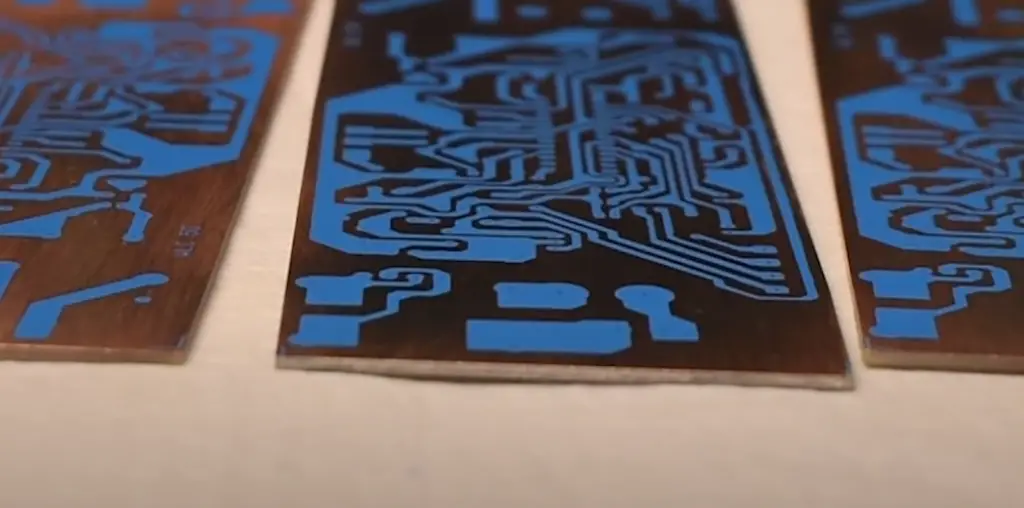
FR-4 is the most widely used type of PCB substrate and is suitable for a wide range of applications. It is a glass-reinforced epoxy laminate material that provides good mechanical, electrical, and thermal properties. FR-4 is suitable for high-frequency applications and has a high glass transition temperature, making it resistant to heat and stress.
PTFE (Teflon)
PTFE or Teflon is a high-performance plastic material that is used for high-frequency and high-speed applications. It has excellent electrical properties, including a low dielectric constant and low loss tangent, making it ideal for microwave and RF circuits. PTFE substrates are also resistant to high temperatures and chemicals.
Metal Substrates
Metal substrates are made of a metal core, typically aluminum or copper, coated with a dielectric layer. They are used in high-power and high-heat applications, such as LED lighting and power electronics. Metal substrates have excellent thermal conductivity, which helps to dissipate heat away from the components, and also provide good mechanical stability.
LTCC
LTCC or low-temperature co-fired ceramics is a type of ceramic substrate that is used in high-frequency applications. It is made of multiple layers of ceramic material that are co-fired together at a low temperature. LTCC substrates provide excellent electrical properties and are capable of handling high frequencies, making them suitable for microwave and RF applications [6].
Flexible Substrates
Flexible substrates are made of thin, flexible material, such as polyimide or PET, that can be bent or shaped to fit into tight spaces. They are used in applications such as wearable technology, medical devices, and aerospace technology. Flexible substrates provide good mechanical flexibility and can withstand repeated bending and flexing without cracking or breaking.
Rigid-Flex Substrates
Rigid-flex substrates are a combination of rigid and flexible substrates that are bonded together to create a single PCB. They are used in applications where space is limited and where the board needs to be flexible to fit into a specific shape or design. Rigid-flex substrates provide the benefits of both rigid and flexible substrates, including good mechanical stability and flexibility.
Polyimide
Polyimide is a high-performance plastic material that is used in high-temperature and high-stress applications. It has excellent thermal and chemical resistance, making it suitable for aerospace and automotive applications. Polyimide substrates also provide good electrical properties and can handle high frequencies.
CEM
CEM or composite epoxy materials are similar to FR-4 substrates but are made with different types of fillers and reinforcements. They are used in low- to medium-cost applications where high performance is not required. CEM substrates provide good mechanical and electrical properties and are suitable for a wide range of applications.
Alumina
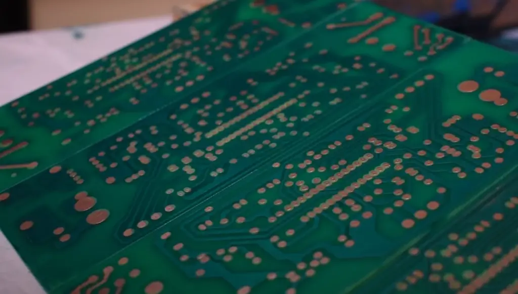
Alumina PCB substrates are made of aluminum oxide ceramic material. They have excellent thermal conductivity and are commonly used in high-power applications where heat dissipation is critical. Alumina substrates are also used in applications that require high frequency and low loss.
What Can Types of Substrate Materials Be Used in High-Frequency PCBs?
There are several types of substrate materials that can be used in high-frequency PCBs, but some are more suitable than others. High-frequency PCBs require substrate materials that have a low dielectric loss, low dielectric constant, and high thermal conductivity.
Some common substrate materials used in high-frequency PCBs include:
- PTFE (Polytetrafluoroethylene): PTFE is a type of plastic with excellent electrical properties, including a very low dielectric constant and low loss tangent, making it ideal for high-frequency applications. PTFE is also resistant to high temperatures, making it suitable for high-temperature applications;
- Ceramics: Ceramics are excellent insulators and have high thermal conductivity, making them suitable for high-frequency and high-power applications. Ceramic substrates are also highly stable and have low thermal expansion, making them ideal for use in extreme environments;
- LCP (Liquid Crystal Polymer): LCP is a type of plastic that has high-frequency characteristics, low dielectric loss, and good thermal stability. LCP substrates are also highly flexible, making them ideal for use in flexible PCBs;
- Rogers: Rogers is a brand of high-performance substrate materials that are specifically designed for high-frequency applications. Rogers substrates are made from a variety of materials, including ceramic-filled PTFE, and offer excellent electrical and mechanical properties [7];
What Would Material Be the Best Choice for Heat Conductivity?
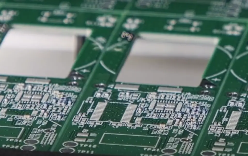
When it comes to heat conductivity, the best material choice for PCB substrates is typically a material that has high thermal conductivity. This is important because the substrate material needs to be able to dissipate heat effectively to prevent the components on the PCB from overheating and potentially malfunctioning or failing.
Copper is one of the best materials for heat conductivity, but it is not commonly used as a substrate material because it is not a good electrical insulator. Instead, some common substrate materials that offer high thermal conductivity include:
Aluminum is a metal with a high thermal conductivity that is often used as a substrate material for PCBs in high-power applications. It is relatively inexpensive and can be used in both single-layer and multilayer PCBs.
Copper-clad laminates are made by laminating a layer of copper to a substrate material, which can be made from a variety of materials, including fiberglass, paper, or ceramic. The copper layer provides excellent thermal conductivity, while the substrate material provides insulation and mechanical stability.
Metal core PCBs have a metal core, typically made from aluminum or copper, that provides high thermal conductivity. The metal core is sandwiched between layers of substrate material and copper to form a PCB [8].
How to Select the Best PCB Substrate Material?
Selecting the best PCB substrate material depends on several factors, including the requirements of the application, the level of performance needed, and the cost and availability of the materials.
Here are some key factors to consider when selecting the best PCB substrate material:
- Electrical properties: The electrical properties of the substrate material, such as dielectric constant and loss tangent, can impact the performance of the PCB. For high-frequency applications, substrates with low dielectric loss and constant are preferred;
- Thermal properties: The thermal properties of the substrate material, such as thermal conductivity and coefficient of thermal expansion, are important for dissipating heat generated by components on the PCB;
- Mechanical properties: The mechanical properties of the substrate material, such as stiffness, strength, and flexibility, are important for ensuring the PCB can withstand stress and strain during use;
- Cost: The cost of the substrate material can impact the overall cost of the PCB, and more expensive materials may be required for high-performance applications;
- Availability: Some substrate materials may be harder to source or may have longer lead times, which can impact the timeline for PCB production;
- Environmental conditions: The operating environment for the PCB, including temperature and humidity, can impact the suitability of certain substrate materials [9];
FAQ
1. What are the 3 types of PCB?
The three types of PCB (Printed Circuit Board) are single-sided, double-sided, and multi-layer PCBs. Single-sided PCBs have circuitry on only one side of the board, while double-sided PCBs have circuitry on both sides of the board. Multi-layer PCBs have multiple layers of conductive material separated by insulating layers.
2. What are the two common types of substrate materials used in a printed circuit board?
The two common types of substrate materials used in a printed circuit board are FR4 (Flame Retardant 4) and Rogers substrates. FR4 is a composite material made of woven fiberglass cloth and epoxy resin, while Rogers substrates are high-performance laminates made of a ceramic-filled PTFE (Polytetrafluoroethylene) material.
3. What type of resin would be used for PCB boards?
Epoxy resin is commonly used in the production of PCB boards due to its excellent electrical insulation properties, dimensional stability, and adhesion to various substrate materials.
4. What is the difference between PCB FR1 and FR4?
The main difference between PCB FR1 and FR4 is the substrate material used. FR1 is made of paper-reinforced phenolic resin, while FR4 is made of woven fiberglass cloth-reinforced epoxy resin. FR4 has better electrical and thermal properties than FR1 and is more commonly used in modern electronic devices.
5. What resin is used in FR4?
Epoxy resin is the most commonly used resin in FR4 substrate material. It provides good electrical insulation and adhesion to the fiberglass cloth, resulting in a strong and durable substrate material.
6. What is the most common PCB substrate?
FR4 is the most common PCB substrate due to its excellent electrical insulation properties, low cost, and compatibility with various manufacturing processes.
7. What are the different types of polymer substrates?
The different types of polymer substrates used in PCB manufacturing include polyimide, polyester, and polycarbonate. These materials offer good thermal stability, flexibility, and chemical resistance [10].
8. What is type 4 PCB?
There is no official classification for type 4 PCB. The numbering system usually refers to the number of copper layers in a PCB, so a type 4 PCB would have four copper layers.
9. What is the cheapest PCB substrate?
Paper-reinforced phenolic resin (FR1) is one of the cheapest PCB substrate materials available. However, it is not suitable for high-performance or high-reliability applications due to its relatively poor electrical and thermal properties.
10. What is the difference between type 2 and type 3 PCB?
Type 2 PCBs have two copper layers, while type 3 PCBs have three copper layers. The additional copper layer in type 3 PCBs allows for more complex circuitry and improved signal integrity [11].
11. Is G10 the same as FR4?
G10 is a type of FR4 substrate material made of woven fiberglass cloth and epoxy resin. However, G10 has a higher glass transition temperature and lower moisture absorption than standard FR4, making it more suitable for high-temperature applications.
12. What is the difference between FR4 and FR4 high TG?
FR4 high TG (High Glass Transition Temperature) is a modified version of standard FR4 material. It has a higher Tg than regular FR4, meaning it can withstand higher temperatures before losing its mechanical and electrical properties. The Tg of FR4 is typically around 130-140°C, while the Tg of FR4 high TG can range from 150-180°C.
13. How thick is the FR4 PCB substrate?
The thickness of FR4 PCB substrate can vary depending on the specific application, but common thicknesses range from 0.2mm to 3.2mm.
14. What is the best PCB coating?
The best PCB coating depends on the specific application and environmental conditions. Some common types of PCB coating include conformal coating, which protects against moisture, dust, and other contaminants, and encapsulation, which provides more comprehensive protection against shock, vibration, and extreme temperatures.
15. What is the difference between FR4 and CEM 3 PCB?
CEM 3 (Composite Epoxy Material 3) is a type of substrate material similar to FR4 but with a higher percentage of woven glass cloth and less epoxy resin. This results in a material with lower electrical and thermal properties than FR4 but with better mechanical properties and a lower cost [12].
16. What is another name for PCB substrate?
PCB substrate is also commonly referred to as PCB material or PCB board material.
17. What is the best material for a PCB enclosure?
The best material for a PCB enclosure depends on the specific application and environmental conditions. Common materials for PCB enclosures include aluminum, plastic, and steel, each with its own advantages and disadvantages.
18. What is the difference between FR4 and prepreg?
It is a component of the overall PCB substrate, which includes both prepreg and core materials. FR4 is a specific type of substrate material made of woven fiberglass cloth and epoxy resin, which can be used as both prepreg and core material.
19. What can I use instead of FR4 material?
There are several alternative substrate materials available, such as polyimide, polyester, and PTFE. These materials offer different properties and performance characteristics compared to FR4 and may be better suited for certain applications.
20. Which PCB is better – FR4 or Rogers?
The choice between FR4 and Rogers substrates depends on the specific application requirements. FR4 is a more cost-effective option with good electrical and thermal properties, while Rogers substrates offer higher performance and are better suited for high-frequency applications.
21. Why is FR4 used in PCBs?
FR4 is used in PCBs due to its excellent electrical insulation properties, high mechanical strength, low cost, and compatibility with various manufacturing processes. It is also widely available and has a proven track record in electronic devices.
22. What is the difference between FR4 and CEM 1?
CEM 1 (Composite Epoxy Material 1) is a type of substrate material similar to FR4 but with a lower percentage of woven glass cloth and more paper-based materials. This results in a material with lower mechanical and electrical properties than FR4 but with a lower cost.
Useful Video: Circuit Board Types | How to use Circuit Boards | PCB Guide | Breadboards
References
- https://blog.matric.com/pcb-substrate-types
- https://www.proto-electronics.com/blog/characteristics-details-and-types-of-pcb-substrates
- https://www.ourpcb.com/pcb-substrate-material.html
- https://tempoautomation.com/blog/how-to-select-the-best-printed-circuit-board-material-for-your-design/
- https://www.pcbnet.com/blog/pcb-substrate/
- https://www.raypcb.com/pcb-substrate-material/
- https://www.mokotechnology.com/pcb-substrate/
- https://www.pcbcart.com/pcb-capability/pcb-materials.html
- https://www.ourpcb.com/pcb-substrate-material.html
- https://tempoautomation.com/blog/how-to-select-the-best-printed-circuit-board-material-for-your-design/
- https://www.pcbnet.com/blog/pcb-substrate/
- https://blog.matric.com/pcb-substrate-types







Leave a Reply