If you’re in the field of electrical engineering, chances are that you already know what impedance and inductance are. But for those who don’t have a grasp of this complex subject yet, understanding the differences between these two concepts can be difficult. In this blog post, we will explore inductance vs. impedance: how they are different from each other, their effects on electric circuits and how to measure them correctly. Whether you’re new to this topic or just curious about it, by reading through this article, hopefully you will gain a better insight into this important aspect of electrical engineering.
What Is Impedance?
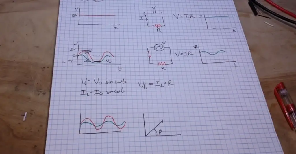
Resistance, or R, is the opposition to direct current (DC) flow in an electrical component or device. Capacitance, or C, is the ability of a device to store electric charge when voltage is applied across it. Inductance, or L, represents how much energy can be stored in a coil due to its magnetic field. The impedance of a circuit is equal to the square root of (R^2 + X^2), where X equals either capacitive reactance (Xc) or inductive reactance (XL).
In practical terms, impedance can be used to calculate the amount of power that a circuit will consume or store. To understand this better, let’s take a look at inductance and its role in impedance. [1]
What Is Inductance?
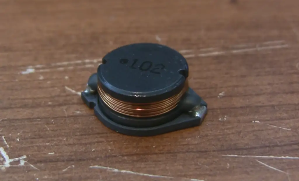
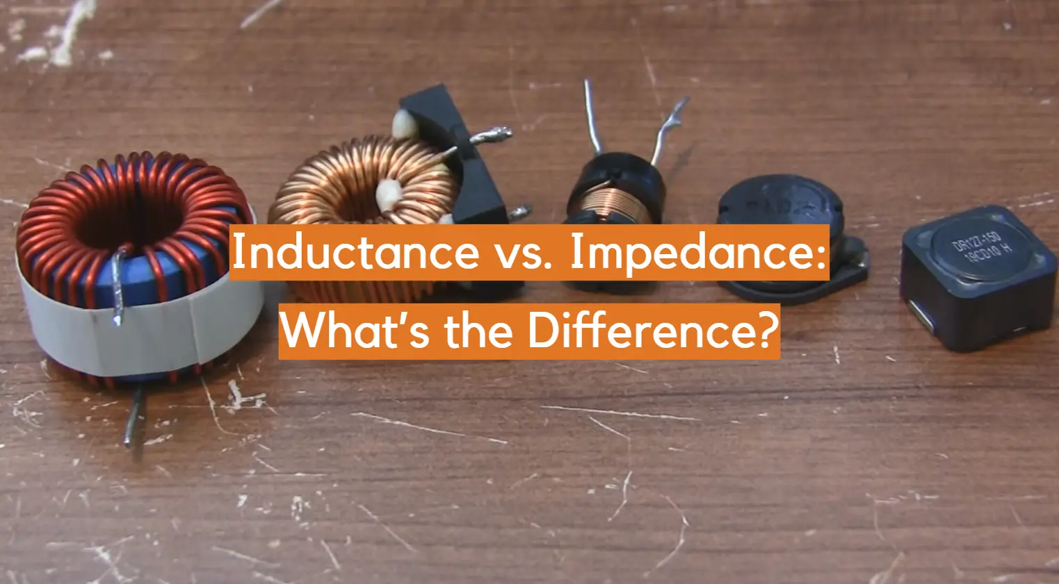
Inductance is an electrical property that describes how a certain circuit behaves when it has a changing current. The symbol used to represent it in equations is L and its unit of measurement is Henries (abbreviated as H). The value of inductance varies depending on factors such as the type and number of turns involved in the circuit, coil diameter, wire length, core material, etc.
Inductance works similarly to capacitance since it also stores energy in a magnetic field when there’s a change in current flow. However, unlike capacitance which opposes changes in voltage, inductance opposes changes in current. This means that as current increases or decreases within the loop environment of a coil or transformer with inductance, the energy stored in the magnetic field will increase or decrease accordingly.
Inductance is also associated with what’s known as ‘back EMF’ (electromotive force). This occurs when a changing current within an inductor induces an opposite voltage that opposes the applied voltage. When this happens, it causes a drop in total circuit impedance which can result in unwanted effects such as oscillation and instability.

Inductance vs. Impedance: What’s the Difference?
Inductance and impedance are both electrical terms associated with the flow of electricity, but understanding their differences is important for proper circuit operation. Inductance is the property of a coil or wire to oppose any change in current. Impedance, on the other hand, is the combination of resistance and reactance that an alternating current (AC) encounters when traveling through a medium such as a cable or inductive device. Resistance restricts current while reactance opposes changes in voltage. In order for AC power to pass through a system without being affected by either factor, it must have low impedance.
The relationship between inductance and impedance can be seen in two ways. First, when an inductor is connected across an alternating current source, its presence increases the total impedance of the circuit. This is because inductors have both an electrical resistance and a property called “reactance,” which opposes voltages that vary from their initial value. When combined with other resistive components in a circuit, a total impedance can be calculated.
The second way to look at the relationship between inductance and impedance is by considering how inductors interact with capacitors in AC circuits. When these two elements are connected in parallel across an alternating current source, the capacitance and reactance of each component will act together to form a specific type of “impedance matching network” designed to provide balanced power delivery throughout the circuit. In this scenario, understanding both inductance and impedance is essential for proper design and operation. [2]
In summary, inductance and impedance are both electrical terms associated with the flow of electricity. Inductance is the property of a coil or wire to oppose any change in current while impedance is the combination of resistance and reactance that an alternating current encounters when traveling through a medium. In order for AC power to pass through a system without being affected by either factor, it must have low impedance. Understanding the relationship between these two concepts can be key to designing effective circuits that utilize both capacitors and inductors together.
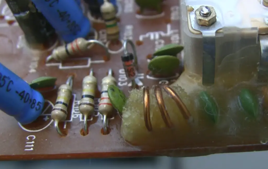
Inductive Reactance
It is a measure of the opposition that an inductor will present to current flow when voltage is applied across it. This type of reactance can also be referred to as impedance, which is a technical term describing the combined resistance and reactance to alternating current (AC). The main difference between inductive reactance and impedance is that impedance takes into account both resistance and capacitive or inductive reactance, whereas inductive reactance only considers the effect of the inductor on AC current. In other words, while both terms describe how much a circuit opposes voltage or current changes, impedance considers more than just reaction by an inductor.
Inductors are used in electronic circuits for their ability to store energy in their coils in the form of a magnetic field. The inductance of an inductor is determined by its size, the number of turns of wire on the coil, and the type of core material used in the construction of the inductor. When voltage is applied across an inductor, it causes a change in current flow through that component. This changing current induces a back emf or counter-electromotive force (EMF) proportional to the rate of change in current flow through it. [3]
Impedance Triangle
The relationship between inductance, capacitance, and resistance is commonly represented using the impedance triangle. Impedance is defined as the total opposition that a circuit presents to alternating current. The impedance triangle helps explain how these three components interact with each other when an AC voltage is applied to a circuit. The three sides of the triangle represent all possible combinations of R, L, and C in series or parallel circuits.
For example, if there were two resistors (R1 & R2) in series with an inductor (L) then the total equivalent impedance would be given by: Z = R1 + R2 + jωL where jω represents the angular frequency times j which equals -1. This equation can then be used to calculate the total impedance of any combination of resistors, inductors and capacitors.
The impedance triangle also provides an easy way to visualize how different combinations of components interact when a voltage is applied to the circuit. By understanding the impedance triangle, engineers can quickly determine what components will work best in a given situation by analyzing how they affect overall circuit performance.
In summary, understanding the relationship between inductance and impedance is essential for designing efficient circuits that perform as intended. The impedance triangle makes it easier to visualize this relationship and helps designers create effective electrical systems with minimal effort. Knowing the basics about this concept will go a long way towards creating reliable electronic systems. Ultimately, learning about inductance vs. impedance will help engineers create better circuits and systems that will provide superior performance.
Power Factor
It is key in the discussion of inductance and impedance. It’s a measure of how much power is actually used by an electrical system, opposed to how much power is wasted as heat or lost through losses due to resistance. The higher the Power Factor, the more efficient the system is. Inductors have a higher Power Factor than resistors and capacitors because they store energy in their magnetic fields and return that energy back into the circuit. This helps reduce losses from heat and improves efficiency overall. Capacitors also help improve Power Factor because they store energy in their electric fields rather than having it dissipate as heat. By combining resistors, inductors, and capacitors into a single system, engineers can optimize for both total impedance and power factor. [4]
The relationship between inductance and impedance is an important factor in designing electrical systems, as the two concepts are closely related.
Inductors create a magnetic field when current passes through them which resists any change in current flow, increasing the overall impedance of the system. By understanding how these two concepts interact with each other, engineers can design more efficient systems that require less energy to operate.
Is Impedance An Inductive Quantity?
Impedance is sometimes used interchangeably with inductance when describing electrical circuits. In many cases, this can be a valid comparison, as both impedance and inductance are measured in ohms (Ω).
The main difference between impedance and inductance lies in the fact that impedance involves other components of electricity such as capacitance and resistance. Impedance takes into account all of these components to measure the opposition that an electric current experiences due to its frequency. This means that when measuring impedance, we must take a number of factors into account- including not only inductive reactance but also capacitive reactance and resistance.
Even though there is overlap between the two terms, it’s important to note that impedance is not an inductive quantity in itself. In other words, impedance measures the total opposition to current flow through a circuit while inductance measures the ability of a coil (or any device) to store energy in its magnetic field.
In summary, impedance and inductance are two different electrical phenomena that measure different aspects of electricity. While one may be used interchangeably with the other, it’s important to remember that impedance is not an inductive quantity. It takes into account all factors of electricity- including capacitance and resistance- when measuring opposition. Understanding this difference can help you better understand both concepts and how they affect your circuits. [5]
Definition of Quality Factor Q
Quality factor Q, sometimes referred to as Q-factor, is a measure of how efficiently a device absorbs and dissipates energy. It describes the ratio between the reactive power stored in the inductor or capacitor (depending on whether we are discussing inductive or capacitive impedance) and its equivalent resistive loss power. In other words, it tells us how much of the total power supplied to the device is stored in the form of energy and how much is lost due to resistance. The higher this number, the more efficiently energy is being stored and not wasted. Most circuits have an optimal quality factor range that should be maintained for best performance. For example, if we wanted to design an amplifier with low distortion, then we would want our Q-factor to be as high as possible. On the other hand, if we wanted to design a filter with steep roll off characteristics, then a lower Q-factor would be desired.
In terms of impedance, quality factor Q is very useful in understanding how much of the total power supplied to a circuit is being stored and released in the form of inductive or capacitive reactance and how much is lost due to resistance. The higher this number, the more efficient the device operates. Quality factor Q also has implications for frequency response since it affects the shape of the Bode plot (graphical representation of signal versus frequency) and therefore plays an important role in determining how well a circuit can respond to different frequencies. When designing any type of electrical system, understanding how quality factor Q affects impedance is essential for successful results.
FAQ
What is the relation between inductance and impedance?
Impedance is the opposition to current flow that includes both resistance and the reactance due to capacitance or inductance. In terms of electrical energy, inductive reactance is the opposition offered by an inductor to alternating current and is equal in magnitude but opposite in phase to the applied voltage. It differs from resistance because it increases as the frequency of the applied voltage increases.
How does impedance depend on inductance?
The impedance of a circuit depends upon its total effective resistance and reactances of its components, including those caused by capacitors and inductors. Reactance caused by an inductor (inductive reactance) increases with increasing frequency and is proportional to the square root of frequency multiplied by inductance (Xl = 2πfL). As frequency increases, the inductive reactance increases to a point where it may dominate the rest of the circuit components, making impedance dependent on inductance.
What is the difference between inductance and impedance?
Inductance is an electromagnetic property of a component or circuit that opposes changes in current flowing through it. It is measured in henries (H) and can be calculated based on the physical dimensions of its coils or windings. Impedance, on the other hand, is a measure of total opposition to alternating current flow that includes both resistance and reactance due to capacitance and inductance. Inductive reactance increases with increasing frequency and makes impedance dependent on inductance. Therefore, while they are related, inductance and impedance are two distinct electrical properties.
What is the role of capacitance in impedance?
The reactance due to capacitance (capacitive reactance) decreases with increasing frequency and is equal to 1/(2πfC). As frequency increases, the capacitive reactance decreases until it may be neglected or dominated by other circuit components. When this happens, impedance becomes dependent on the resistance rather than the capacitance. Therefore, while both inductive and capacitive reactances can affect a circuit’s impedance, their roles depend on the frequency of operation. At some frequencies one will dominate while at others they will both contribute in varying amounts.
Do inductors have impedance?
The answer is yes, they do. In fact, the impedance of an inductor is defined as its opposition to current change in a circuit over time. An inductor’s impedance is also referred to as its inductive reactance because it reacts against any changes in the current flowing through it. An inductor’s impedance increases with increasing frequency which means that high-frequency signals are attenuated or reduced more than low-frequency ones. This makes inductors useful components for filter circuits and other applications where signal frequencies need to be filtered out or controlled.
Does the inductor increase impedance?
Yes, the inductor does increase impedance. Impedance is a measure of a circuit’s resistance to alternating currents and is measured in Ohms. A capacitor and an inductor both have their own influence on impedance due to their current-limiting effects. Generally speaking, when an inductor is present in a circuit it increases the overall impedance of that circuit. This can be beneficial as it can help limit current flow which helps keep signal strength up and protect other components from overloading or overheating. Additionally, higher impedances also tend to decrease noise levels within a circuit, making them useful for RF applications.
Useful Video: Inductance basics
Conclusion
In conclusion, the main difference between inductance and impedance lies in their definitions. Inductance is a measure of the opposition to an AC current caused by an inductor coil, whereas impedance is a measure of all components’ effects on an AC current flowing through a circuit. Both have an effect on the current flow, but one measures resistance only while the other measures both resistance and reactance. Understanding these two concepts and how they work together can help you design more effective electrical circuits. As always, safety first; make sure to read up on any warnings or safety information related to working with electricity before beginning your project!
References
- https://www.circuitsgallery.com/impedance-vs-inductance/
- https://passive-components.eu/inductors-inductance-impedance-and-losses/
- https://www.physlink.com/education/askexperts/ae517.cfm
- https://www.motioncontroltips.com/whats-the-difference-between-resistance-reactance-and-impedance/
- https://eepower.com/capacitor-guide/fundamentals/impedance-and-reactance/
- https://electronicsclub.info/impedance.htm







Leave a Reply