In the fascinating world of electrical engineering and circuit analysis, understanding the distinctions between fundamental concepts is essential for designing efficient and functional systems.
Among the crucial properties encountered in this realm are inductance and impedance.
On the other hand, impedance is a comprehensive measure of the total opposition that a circuit presents to the flow of alternating current, taking into account resistance, capacitance, and inductance.
By grasping the nuances between these two vital electrical parameters, engineers, students, and enthusiasts alike can gain a deeper understanding of how AC circuits function, paving the way for innovative designs and problem-solving in the dynamic world of electrical engineering. So, let’s embark on a journey to explore the intricate relationship between inductance and impedance and discover the profound impact they have on the world of electrical circuits.
What Is Inductance?
Inductance is a fundamental concept in the field of electromagnetism, playing a crucial role in electrical circuits and the functioning of electronic devices. It is one of the key parameters that govern the behavior of inductors, a type of passive electrical component widely used in various applications.
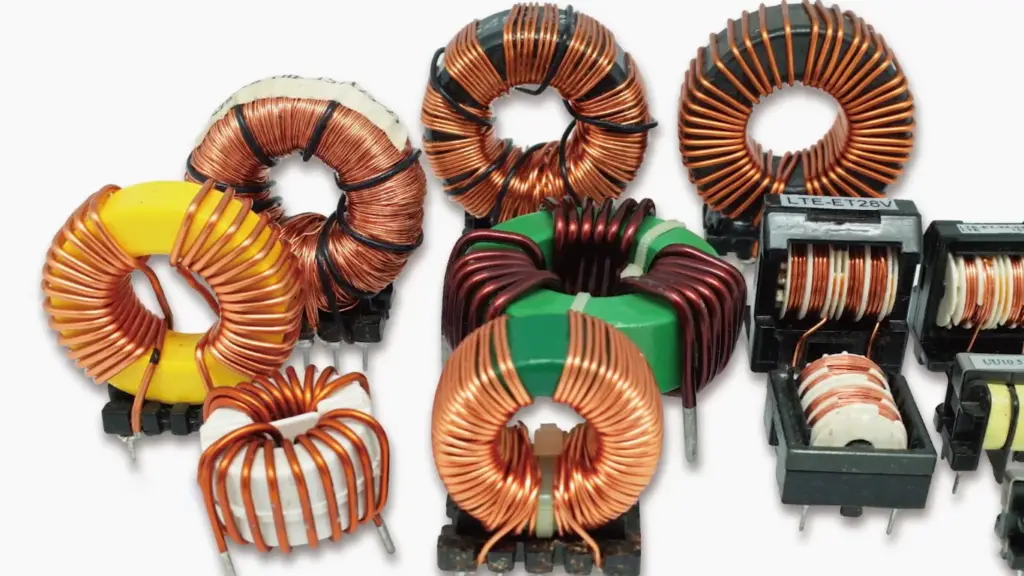
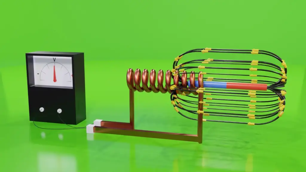
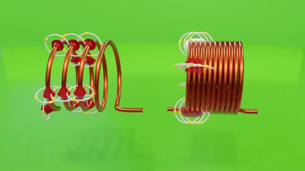
Inductance is the property of an electrical conductor or coil that describes its ability to store energy in the form of a magnetic field when an electric current passes through it [1]. When current flows through a wire or a coil, it generates a magnetic field around it. This magnetic field induces a counter-electromotive force (EMF) that opposes the change in the current. In simple terms, inductance resists the flow of current, causing a delay in its response to changes in voltage.
The Inductor
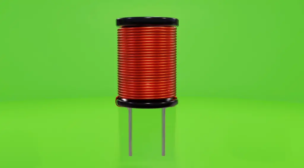
An inductor is a device specifically designed to harness the phenomenon of inductance. It consists of a coil of wire, often wound around a core made of magnetic material, which increases the efficiency of energy storage. Inductors come in various shapes and sizes, catering to different applications. They can be found in transformers, chokes, power supplies, electronic filters, and even in radio frequency circuits.
Characteristics of Inductance
Inductors, the components exhibiting inductance, possess unique characteristics that set them apart from other circuit elements. Some key characteristics of inductance include:
- Energy Storage: As mentioned earlier, inductors can store energy in their magnetic fields. This property makes them essential in applications where energy needs to be temporarily stored and released, such as transformers and energy storage systems;
- Reactance: The reactance of an inductor is its opposition to changes in the current flow. In an AC circuit, the reactance of an inductor is proportional to the frequency of the AC signal. Higher frequencies encounter greater opposition from the inductor;
- Time-Dependent Behavior: Inductors respond to changes in current over time. When the current passing through inductor changes, the magnetic field takes time to build up or collapse, resulting in time-dependent behaviors in circuits;

Mathematical Representation
Inductance is measured in henrys (H), named after the American scientist Joseph Henry, who made significant contributions to the study of electromagnetism. Mathematically, inductance is represented by the symbol “L”. The amount of inductance depends on the number of turns in the coil, the shape of the coil, and the presence of core material. It is calculated using the formula:
L = (μ₀ * μᵣ * N² * A) / l
where:
- L is the inductance in henrys (H)
- μ₀ is the permeability of free space (approximately 4π × 10⁻⁷ H/m)
- μᵣ is the relative permeability of the core material
- N is the number of turns in the coil
- A is the cross-sectional area of the coil
- l is the length of the coil
Inductance in Action
Inductance has significant implications in electrical circuits. When the current in inductor changes, the stored magnetic energy induces an opposing voltage, creating a temporary resistance to any variations in the current. This behavior leads to interesting effects like energy storage, electromagnetic interference, and phase shifts in alternating current circuits.
Inductors in Series and Parallel
When inductors are connected in series, their total inductance is the sum of their individual inductances. This is because the total magnetic field generated by the current flow in each coil is additive. The total inductance can be calculated using the formula:
Ltotal = L1 + L2 + … + Ln
When inductors are connected in parallel, their total inductance is dependent on the individual inductances and the way they are connected. If the inductors are connected in parallel with the same polarity, their total inductance can be calculated using the formula:
1/Ltotal = 1/L1 + 1/L2 + … + 1/Ln
However, if the inductors are connected in parallel with opposite polarities, the total inductance may be less than the value of the smallest inductor. This is because the magnetic fields generated by the coils can cancel each other out to some extent.
What Is Impedance?
Impedance is a fundamental concept in electrical engineering and plays a crucial role in understanding the behavior of electrical circuits. It is a complex quantity that combines resistance, capacitance, and inductance, and it describes the opposition a circuit presents to the flow of alternating current (AC).
Characteristics of Impedance
Impedance encapsulates the overall opposition to electrical flow in a circuit. It combines the resistive, capacitive, and inductive effects into a single entity. Key characteristics of impedance include:
- Complex Nature: Impedance in AC circuits is represented by complex numbers, with a real part (resistance) and an imaginary part (reactance). This complex nature accounts for both magnitude and phase shift, affecting the behavior of AC circuits;
- Frequency Dependency: Impedance varies with the frequency of the AC signal. Different circuit elements contribute differently to the overall impedance at different frequencies. Capacitors and inductors have opposing effects on impedance as frequency changes;
- Total Circuit Behavior: Impedance determines how a circuit responds to AC signals. It influences current and voltage relations, power transfer, and signal filtering in various electrical systems;
Mathematical Representation
Impedance is represented as a complex quantity and is denoted by the symbol “Z”. It has two components: magnitude (|Z|) and phase angle (θ). The magnitude of the impedance is measured in ohms (Ω), similar to resistance. The phase angle is measured in degrees and represents the phase shift between voltage and current in the AC circuit.
Impedance can be expressed in the form:
Z = |Z| * e^(jθ)
where:
- |Z| is the magnitude of the impedance
- j is the imaginary unit (√(-1))
- θ is the phase angle in degrees
Components of Impedance:
- Resistance (R): This component represents the opposition to the flow of current in a circuit due to the material’s inherent resistance. It is the only real part of the impedance and is unaffected by the frequency of the AC;
- Capacitance (Xc): Capacitors store energy in an electric field when an AC voltage is applied. The capacitive reactance (Xc) is the imaginary part of impedance due to the capacitors and is inversely proportional to the frequency of the AC;
- Inductance (Xl): Inductors store energy in a magnetic field when an AC current flows through them. The inductive reactance (Xl) is the imaginary part of impedance due to the inductors and is directly proportional to the frequency of the AC;
Impedance in AC Circuits
In an AC circuit, the impedance is calculated by considering the combination of resistance, capacitance, and inductance. The total impedance (Z) is found using the following formula:
Z = √(R² + (Xl – Xc)²)
The phase angle (θ) is calculated as the arctangent of the difference between inductive and capacitive reactances:
θ = atan((Xl – Xc) / R)
Impedance in Series and Parallel
When resistors are connected in series, their total resistance is the sum of their individual resistances. This is because the current must flow through each resistor in turn, and the voltage drop across each resistor is additive. The total resistance can be calculated using the formula:
Rtotal = R1 + R2 + … + Rn
When resistors are connected in parallel, their total resistance is dependent on the individual resistances and the way they are connected. If the resistors are connected in parallel, their total resistance can be calculated using the formula:
1/Rtotal = 1/R1 + 1/R2 + … + 1/Rn
In a similar way, the total impedance of a circuit can be calculated when resistors and inductors are combined in series and parallel. The rules of series and parallel circuits apply, and the total impedance can be calculated using Kirchhoff’s laws and other circuit analysis techniques.
Inductance and Impedance in Electrical Circuits
Inductance and impedance are both important in the design and analysis of electrical circuits. Inductors are commonly used in electrical circuits to store energy in a magnetic field and release it when the current changes. They are used in filters, oscillators, transformers, and many other applications.
Impedance, on the other hand, is important because it describes the total opposition to the flow of an alternating current by a circuit. This includes both resistance and reactance. Impedance is used to describe the behavior of electrical circuits in response to an alternating current.
For example, when an alternating current is applied to a circuit containing an inductor, the current will lag behind the voltage due to the inductance. This causes a phase shift between the voltage and current, which results in a complex impedance. The impedance of the circuit depends on the frequency of the alternating current, as well as the values of the inductance, resistance, and capacitance.
Inductance and impedance are two important concepts in electrical engineering that are often confused with each other. While they are related, they are not the same thing. Inductance refers to the property of an electrical circuit that opposes a change in current flow, while impedance refers to the total opposition to the flow of an alternating current (AC) by a circuit. Understanding the difference between these two concepts is crucial for developing efficient electrical circuits and systems.
At its most basic level, inductance is a property of an electrical device, such as a coil or solenoid, that generates a magnetic field in response to a changing current. This magnetic field induces a voltage that opposes the change in current. This opposition to current change is known as inductance. It is measured in Henrys (H), and its symbol is L.
Impedance, on the other hand, is the total opposition to the flow of an alternating current (AC) by a circuit. It is the combined effect of resistance, capacitance, and inductance in a circuit. It is measured in ohms, and its symbol is Z.
In a circuit that contains only resistance, the impedance is simply equal to the resistance. However, in a circuit that contains inductance, the impedance is more complex. This is because the inductance causes a phase shift between the voltage and current.
To understand this better, let us consider a simple circuit containing a resistor, an inductor, and an alternating current source. The resistor provides resistance, while the inductor provides inductance. The alternating current source provides the alternating current.

As the current flows through the inductor, it generates a magnetic field that opposes the change in current. This opposition to current change results in a phase shift between the voltage and current. This phase shift causes the impedance to be higher than the resistance alone.
To calculate the impedance of this circuit, we use the following formula:
Z = sqrt(R^2 + X^2)
Where R is the resistance and X is the reactance. The reactance is the opposition to the current caused by inductance (in this case). It is calculated as:
X = 2πfL
Where f is the frequency of the alternating current and L is the inductance [3].
So, we can see that the impedance of a circuit containing inductance is a function of the frequency (f) and the inductance (L). As the frequency increases, the reactance also increases, and so does the impedance.
It is important to note that the impedance of a circuit with inductance is not constant for all frequencies. The reactance caused by inductance is directly proportional to the frequency, so the impedance of the circuit will vary with frequency.
In contrast, the resistance of a circuit is independent of frequency. This is why the impedance of a circuit with only resistance is constant for all frequencies. However, in a circuit with inductance, capacitance, or both, the impedance will be a complex function of frequency.
Since impedance is a combination of resistance and reactance, it is represented by a complex number. The real part of the complex impedance represents the resistance, while the imaginary part of the complex impedance represents the reactance. In fact, the impedance can be represented as a vector in the complex plane, with the real part along the horizontal axis and the imaginary part along the vertical axis.
Impedance vs Inductance: Key Differences
Impedance vs. Inductance
Impedance is a comprehensive representation of the total opposition offered by an electrical circuit to the flow of alternating current (AC). It is a complex quantity, combining resistance (R), capacitance (Xc), and inductance (Xl), and is represented as “Z”. The impedance of a circuit takes both magnitude and phase angle into account.
Inductance, on the other hand, is a property specific to inductive elements like coils and conductors. It describes the ability of a component to store energy in the form of a magnetic field when an electric current passes through it. Inductance is measured in henrys (H) and is represented by the symbol ‘L.’
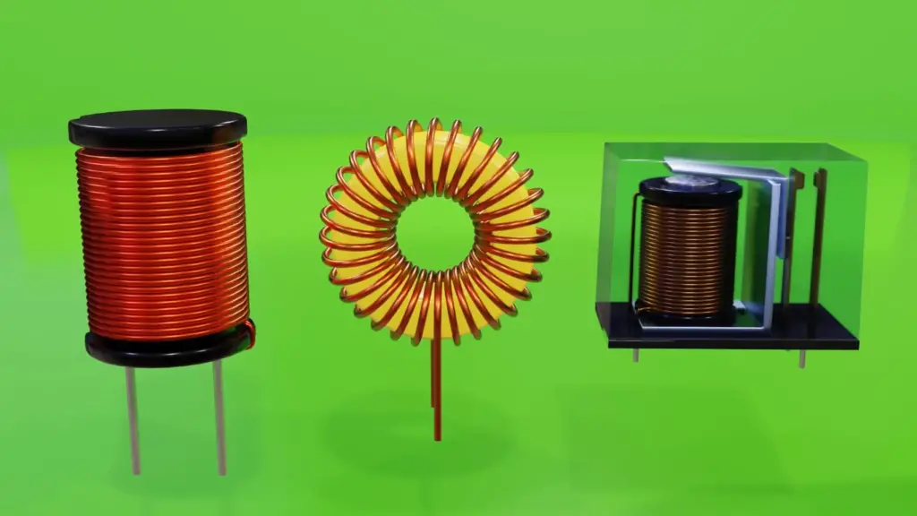
The main difference between impedance and inductance is that impedance considers all factors (resistance, capacitance, and inductance) affecting the flow of AC, while inductance only focuses on the storage of magnetic energy within a specific element [4].
Impedance vs. Reactance
Reactance is an important concept when analyzing AC circuits and is closely related to impedance. It refers to the opposition that inductive (Xl) and capacitive (Xc) elements offer to the flow of alternating current. In the context of inductive reactance, it arises due to the energy storage in magnetic fields in inductors.
Capacitive reactance, on the other hand, arises from the energy storage in electric fields within capacitors. It is denoted by the symbol “Xc” and is inversely proportional to the frequency of the AC.
To better understand the relationship between impedance, resistance, inductive reactance, and capacitive reactance, we can use the impedance triangle. The impedance triangle is a graphical representation that shows the interplay of these three components.
In this triangle, the horizontal side represents resistance (R), the vertical side represents capacitive reactance (Xc), and the hypotenuse represents impedance (Z). The angle between the impedance and resistance sides is the phase angle (θ), indicating the phase shift between voltage and current in the circuit.
The Power Factor
A power factor of 1 (or 100%) indicates maximum efficiency, where all the power supplied to the circuit is used for useful work, with no power wasted. This ideal scenario occurs in purely resistive circuits.
However, in circuits with inductive or capacitive elements, the power factor is less than 1. This means that some power is lost due to the reactive components, and the efficiency decreases. The power factor is calculated as the cosine of the phase angle (θ) between voltage and current.
Power Factor (PF) = cos(θ)
A low power factor can result in increased energy consumption, leading to higher electricity bills. Power factor correction techniques are used in industrial settings to improve power factor values and reduce wastage [5].
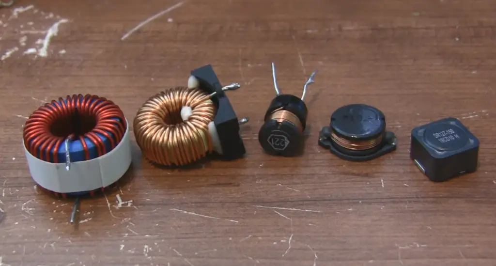
What Is The Impedance of an Inductor?
Impedance is the total opposition offered by an electrical circuit to the flow of alternating current. For inductors, impedance specifically refers to the opposition caused by the inductive reactance (Xl). Unlike resistance (R), which affects direct current (DC) flow, inductive reactance only comes into play when the current is alternating.
Inductive reactance (Xl) arises from the inductor’s ability to store magnetic energy when an AC current flows through it. It depends on the frequency (f) of the alternating current and the inductance (L) of the coil, and it is calculated using the formula:
Xl = 2πfL
Where:
- Xl is the inductive reactance in ohms (Ω)
- π (pi) is a mathematical constant (approximately 3.14159)
- f is the frequency of the AC in hertz (Hz)
- L is the inductance of the coil in henrys (H)
The Impedance of an Inductor:
The impedance of an inductor (Zl) is simply the inductive reactance (Xl) presented as a complex quantity. It is represented as:
Zl = Xl * j
Where:
- Zl is the impedance of the inductor in ohms (Ω)
- j is the imaginary unit (√(-1))
The inclusion of the imaginary unit (j) signifies that the impedance of an inductor has both magnitude and phase angle components, similar to other complex impedances
Magnitude and Phase Angle
The magnitude of the impedance (|Zl|) represents the absolute value of Zl and is calculated as |Zl| = |Xl|. It indicates the total opposition offered by the inductor to the alternating current.
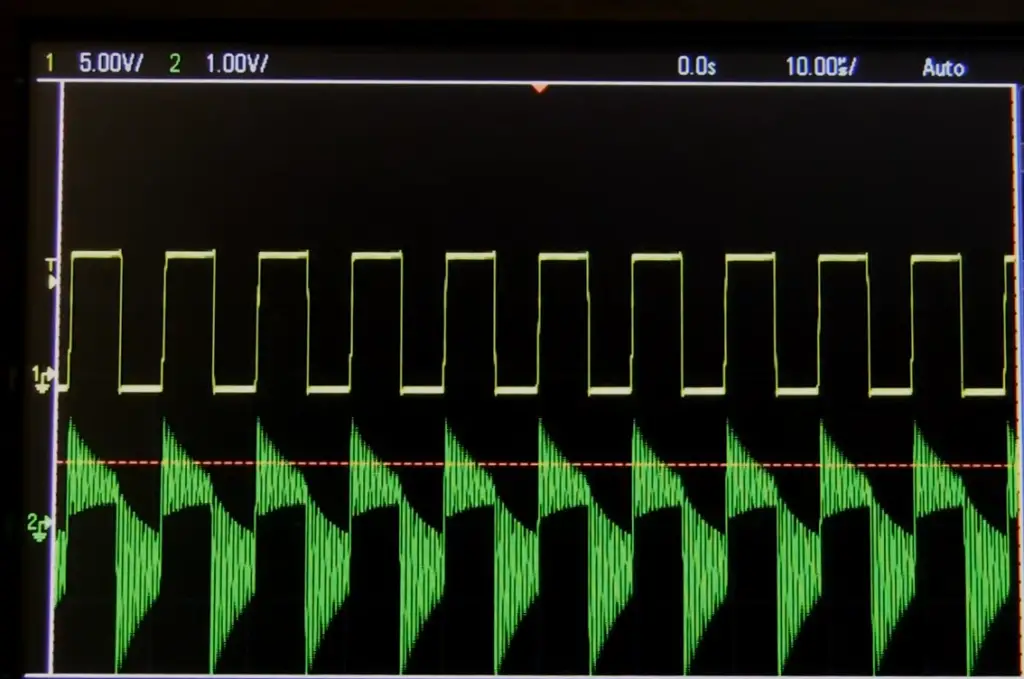
The phase angle (θ) of the impedance represents the phase shift between the voltage and current in the inductor due to the presence of inductive reactance [6]. The phase angle is given by:
θ = atan(Xl / R)
Where R is the resistance in ohms (Ω) of the circuit.
Applications of Impedance in Inductors:
Inductance and impedance find applications in numerous fields of electrical engineering, electronics, and communication. Some notable applications include:
- Transformers: Inductors are crucial components in transformers, which enable efficient voltage transformation and power distribution in electrical grids;
- Inductive Charging: Inductance-based wireless charging systems are used to charge electric vehicles, smartphones, and other electronic devices wirelessly;
- Filters and Oscillators: Impedance-based filters are used to attenuate or pass certain frequencies in electronic circuits. Oscillators, which rely on feedback and resonance, are also built using inductors and capacitors;
- Electromagnetic Compatibility (EMC): Impedance matching techniques are employed to ensure EMC in electronic systems, preventing interference and signal loss [7];
FAQ:
1. Is impedance an inductive quantity?
Impedance is not an inductive quantity in itself. Impedance is a complex quantity that considers the total opposition to the flow of alternating current in a circuit. It comprises resistance (R), inductive reactance (Xl), and capacitive reactance (Xc). While inductive reactance is a component of impedance specific to inductors, impedance also includes resistance and capacitive reactance.
2. What is the difference between impedance and inductive reactance?
The main difference between impedance and inductive reactance lies in their scope. Impedance is a comprehensive measure of the total opposition offered by a circuit to the flow of alternating current. It takes into account both resistance and the effects of inductive and capacitive elements (reactance).
Inductive reactance, on the other hand, is a specific component of impedance and represents the opposition that inductors offer to alternating current due to their ability to store magnetic energy. It depends on the frequency of the AC and the inductance of the coil.
3. How does inductance affect impedance?
Inductance affects impedance through the inductive reactance (Xl) it introduces to the circuit. As the frequency of the alternating current increases, the inductive reactance also increases proportionally. This means that inductors offer higher impedance to higher-frequency AC currents. Inductance plays a crucial role in determining the behavior of circuits, particularly those involving AC components.
4. What is inductance in terms of impedance?
Inductance, in terms of impedance, is the property of an inductor that gives rise to inductive reactance (Xl). Inductive reactance is a function of the inductance (L) of the coil and the frequency (f) of the alternating current. The impedance of an inductor (Zl) is then represented as Zl = Xl * j, where j is the imaginary unit (√(-1)).
5. What is the relationship between resistance, inductance, and impedance?
The relationship between resistance, inductance, and impedance can be understood using the impedance triangle. In this triangle, the resistance (R) is the horizontal side, the inductive reactance (Xl) is the vertical side, and the impedance (Z) is the hypotenuse. The angle between the resistance side and the impedance side represents the phase angle (θ) due to the presence of inductive reactance.
6. What is impedance in simple terms?
In simple terms, impedance is the total opposition an electrical circuit offers to the flow of alternating current. It includes resistance (R) and the effects of inductive reactance (Xl) and capacitive reactance (Xc). Impedance is represented as a complex quantity with both magnitude and phase angle components.
7. How do you convert inductance to impedance?
To convert inductance to impedance, you need to calculate the inductive reactance (Xl) using the formula Xl = 2πfL, where f is the frequency of the alternating current and L is the inductance of the coil. Then, the impedance (Z) of the inductor is represented as Z = Xl * j.
8. What is the difference between impedance and resistance?
The main difference between impedance and resistance lies in their behavior in AC and DC circuits. Resistance (R) is the opposition offered by a component to the flow of direct current (DC) and is a real quantity, measured in ohms (Ω). It remains constant regardless of the frequency of the current.
On the other hand, impedance (Z) is the total opposition offered by a circuit to the flow of alternating current (AC). It is a complex quantity that considers both resistance and the effects of inductive reactance (Xl) and capacitive reactance (Xc). Impedance varies with the frequency of the AC, and it is represented as a combination of magnitude and phase angle.
9. Does impedance reduce voltage?
Yes, impedance can reduce the voltage in an electrical circuit. When there is an impedance in a circuit, the voltage across the impedance and the current through it might not be in phase due to the presence of reactive components (inductive or capacitive). This phase difference can lead to a decrease in the effective voltage delivered to the load.
10. Does inductance cause resistance?
Inductance does not directly cause resistance. Inductance causes inductive reactance (Xl), which is a component of impedance. While inductive reactance introduces opposition to the flow of AC, it is different from resistance, which opposes the flow of DC.
11. How to calculate impedance?
To calculate impedance in an AC circuit, you need to determine the resistance (R), inductive reactance (Xl), and capacitive reactance (Xc) of the components involved. Then, you can use the Pythagorean theorem to find the magnitude of impedance (|Z|) as follows:
|Z| = √(R² + (Xl – Xc)²)
The phase angle (θ) of impedance is calculated as:
θ = atan((Xl – Xc) / R)
12. What is Ohm’s law of impedance?
Ohm’s law of impedance relates the voltage (V) across an impedance (Z) to the current (I) flowing through it. It is represented as:
V = I * Z
This equation is analogous to Ohm’s law for resistance (V = I * R), but in the case of impedance, the current and voltage are phasors due to the presence of reactive components.
13. What increases inductance?
Inductance is primarily determined by the physical characteristics of an inductor, such as the number of turns in the coil, the cross-sectional area, and the presence of core material. Increasing the number of turns or using a magnetic core with higher permeability can increase the inductance of an inductor.
14. What are the two types of impedance?
There are two types of impedance: capacitive impedance and inductive impedance. Capacitive impedance is the opposition offered by capacitors to alternating current due to capacitive reactance (Xc). Inductive impedance is the opposition offered by inductors to AC due to inductive reactance (Xl).
15. Does resistance equal impedance?
Resistance (R) is a component of impedance (Z), but resistance does not equal impedance. Impedance also includes the effects of inductive reactance (Xl) and capacitive reactance (Xc).
16. Does high resistance mean high impedance?
Not necessarily. High resistance does not directly indicate high impedance. Impedance depends on the combination of resistance, inductive reactance, and capacitive reactance in a circuit. A circuit with high resistance and negligible reactance can have a lower impedance than a circuit with low resistance and significant reactance.
17. What is Ohm’s law for inductors?
Ohm’s law for inductors relates the voltage across an inductor (V) to the current flowing through it (I) and the inductive reactance (Xl). It is represented as:
V = I * Xl
This equation shows that the voltage across an inductor is directly proportional to the current flowing through it and the inductive reactance.
18. What is the impedance of a capacitor vs. inductor?
The impedance of a capacitor (Zc) and the impedance of an inductor (Zl) have opposite effects on alternating current. The impedance of a capacitor is given by:
Zc = -j / (2πfC)
where j is the imaginary unit and C is the capacitance of the capacitor. The negative sign indicates that the impedance of a capacitor leads the voltage in phase.
On the other hand, as mentioned earlier, the impedance of an inductor is represented as Zl = Xl * j, where Xl is the inductive reactance. The impedance of an inductor lags the voltage in phase.
19. How do you find the impedance of a coil?
To find the impedance of a coil (inductor), you need to determine the inductive reactance (Xl) and represent it as a complex quantity. The impedance of the coil is then given by:
Z = Xl * j
where j is the imaginary unit (√(-1)).
20. What is another word for impedance?
Another word for impedance is “resistance”. However, it is important to note that while impedance includes resistance, it also considers the effects of inductive reactance and capacitive reactance.
21. Do inductors reduce voltage?
Inductors can cause a voltage drop in AC circuits due to the presence of inductive reactance. When an inductor is connected in series with a load, the inductive reactance leads to a phase shift between voltage and current. This phase shift can lead to a reduction in the effective voltage across the load.
Useful Video: The Differences Between Resistance, Reactance, and Impedance – A Galco TV Tech Tip
References
- https://www.circuitsgallery.com/impedance-vs-inductance
- https://passive-components.eu/inductors-inductance-impedance-and-losses/
- https://en.wikipedia.org/wiki/Electrical_impedance
- https://www.electricalelibrary.com/en/2017/08/18/resistance-capacitance-inductance-impedance-and-reactance/
- https://www.easytechjunkie.com/what-is-inductor-impedance.htm
- https://unacademy.com/content/neet-ug/study-material/physics/differences-between-reactance-and-impedance/
- https://www.motioncontroltips.com/whats-the-difference-between-resistance-reactance-and-impedance/






Leave a Reply