
Ground resistance is an important electrical safety factor that should be checked during any installation or troubleshooting project. In this comprehensive guide, we will answer some of the most common questions about how to measure ground resistance with a multimeter. We’ll provide useful tips and tricks for getting the most accurate readings possible, so you can feel confident in your work. Let’s get started!
What is Ground Resistance
Grounding is the process of creating a conductive path between an electrical system and the earth. This provides a safe route for current to flow in the event of a fault or overload. Grounding also protects against electromagnetic interference (EMI) and static discharge.
Proper grounding can ensure that sensitive electronic equipment operates correctly and safely. It can also improve the performance of electrical systems by reducing voltage fluctuations and minimizing line noise.
There are several ways to create a ground connection, but the most common is to use metal rods or plates buried in the earth. The resistance of this connection is known as ground resistance.
Ground resistance is a measure of how well a conductor, or ground rod, dissipates electrical current into the earth. The earth itself is a good conductor, but the soil and rocks that make up the earth’s surface are not always conductive. This is why it is important to measure ground resistance before using it as a grounding system. The lower the resistance, the better the conductor and the bigger the resistance, the poorer the conductor
Ideally, you’d want the ground to have a resistance of 5 ohms or less, however the appropriate ground resistance will depend on many factors. There are many factors that affect the ground resistance, let’s discuss them. [1], [2], [3]
Type of soil
The type of soil has the most significant effect on the ground resistance. The resistivity of soil varies depending on its composition. For example, sandy soils are very resistive because they tend to lose moisture faster than other soils. Clay soils, on the other hand, are more conductive because they contain more minerals that conduct electricity.
Moisture levels
This indicates that resistivity is also affected by the moisture content of the soil. Dry soil is more resistive than moist soil because water conducts electricity better than air. This is why it is important to measure ground resistance after it rains or during periods of high humidity.
Temperature of the soil
The temperature of the soil also affects ground resistance. Colder temperatures make the soil more resistant to electrical current while warmer temperatures make it more conductive. This is because water freezes at a lower temperature than other substances and ice is a poor conductor.
The mineral composition of the soil
The type of soil you are measuring will affect the ground resistance. As we mentioned, soil with a high clay content is more conductive than sandy soil. This is because clay particles are smaller and have a higher surface area than sand particles.

Igneous rocks, such as granite and basalt resist electricity better than sedimentary rocks, such as limestone and sandstone. This is because igneous rocks are made up of large crystals that do not conduct electricity well.
Obstructions below the ground
The ground resistance is also affected by what is below the ground. If there are rocks, roots, or other obstructions below the surface, they will impede the flow of current and increase the ground resistance.
The size of the conductor
In addition to the composition of the soil, the size of the conductor also affects ground resistance.
A long, thin conductor has a larger surface area than a short, thick conductor. This is because a long, thin conductor has more exposed surface area than a short, thick conductor.
The longer the conductor is, the bigger the resistance. This is because the resistance resistance of a conductor is proportional to its length.
What is a Multimeter?
A multimeter is an electronic device that measures electrical voltage, current, and resistance. It can also be used to test continuity, or the ability of electricity to flow through a material. Multimeters are essential tools for electricians and engineers. They are used to troubleshoot electrical problems and to ensure that circuits are functioning properly.
Multimeters can come in different shapes and sizes. The most basic type is a handheld unit that you can carry around with you. There are also larger benchtop models that stay in one place.
Most modern multimeters have features that make them easy to use. For example, they may have a digital display that shows you the reading, or they may beep when they detect a current.
Multimeters have two probes, or leads, that are used to touch the circuit you want to test. One probe is positive and the other is negative. The probes are connected to the multimeter by wires.
When you touch the probes to a circuit, the multimeter will measure the voltage, current, or resistance of that circuit and display the reading on its screen.
Types of Multimeters
There are two types of multimeters: analog and digital.
Digital multimeters are the most common type of meter used to measure ground resistance. They are easy to use and can provide accurate readings. To use a digital multimeter, simply select the “resistance” mode and touch the probes to the ground you want to test. The reading will appear on the screen.
Analog multimeters are less common than digital ones, but they can also be used to measure ground resistance. To use an analog meter, select the “resistance” mode and touch the black probe to the ground you want to test. The reading will appear on the dial.

Both types of multimeters can be used to measure ground resistance, but digital multimeters are more accurate. This is because they can take into account factors such as temperature and moisture levels.
Digital multimeters also can have the ability to store data. This is useful if you need to keep track of ground resistance over time.
Methods of Determining Ground Resistance
There are three main methods of determining ground resistance: the two-probe method, three-probe method and the four-probe method.
Two-probe method
The two-probe method is the most common and simplest method of measuring ground resistance. This method uses two electrodes placed in the ground at different depths. The multimeter is then connected to these electrodes and a reading is taken. We will only cover this method in this article as it’s the only way to perform ground resistance testing with a multimeter.
Three-probe method
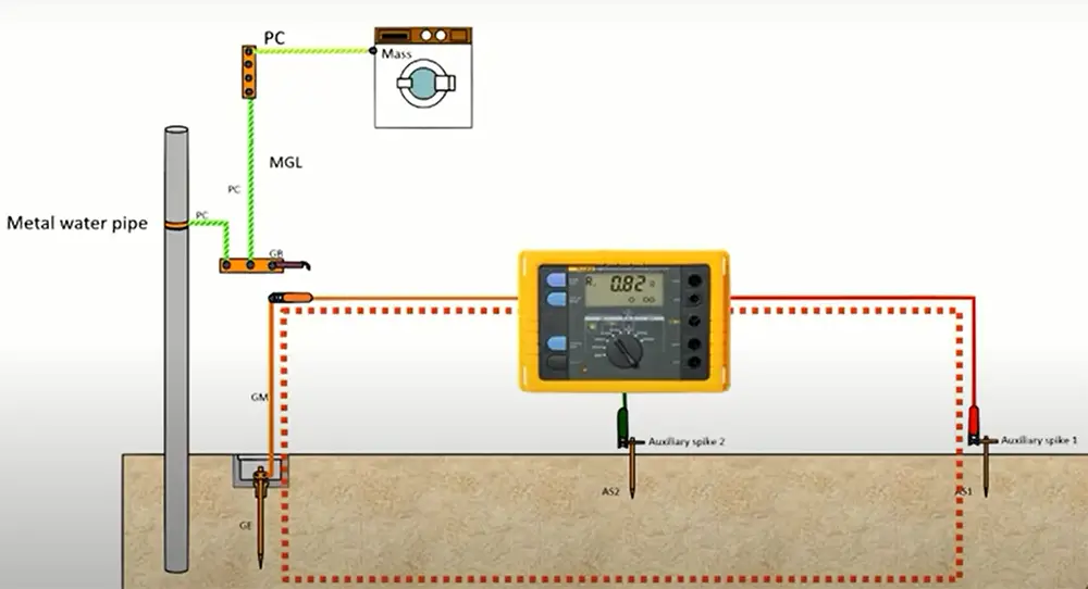
The three-probe method uses two electrically independent electrodes to measure ground resistance. The probes are placed in the ground at different depths and a reading is taken.
Four-probe method
The four-probe method is more accurate than the two-probe method but it is also more complex. This method uses four probes placed in the ground at equal distances from each other. Then the voltage between pairs of probes is measured and resistance is calculated.
This method is accurate because it takes into account the effects of soil resistivity and probe size on ground resistance. It is also relatively easy to set up.
The four-probe method is the most accurate way to measure ground resistance, but it can be time consuming and difficult to set up. If you’re looking for a quick and easy way to measure ground resistance, the two-probe or three-probe methods may be more suitable. [10], [11], [12]
Safety Precautions
Before you begin, it’s important to take some safety precautions. Ground resistance testing can be dangerous if not done properly.

Read instructions carefully
First, make sure you read the instructions carefully. If you’re not sure how to use the multimeter, ask someone for help. Never try to figure it out on your own as this could be dangerous. Also, always follow the manufacturer’s safety guidelines. They will have specific instructions on how to use the multimeter and what precautions you need to take.
Wear protective clothing
When performing ground resistance testing, it’s important to wear protective clothing. This includes gloves, safety glasses and a face mask. The reason for this is that you will be working with electricity. If you come into contact with an electrical current, you could be seriously injured or even killed.
Use the proper tools
In order to safely perform ground resistance testing, you’ll need to use the proper tools. This includes a digital multimeter, gloves, safety glasses and a face mask. Make sure you understand how to use each tool before you begin.
Don’t use the multimeter if its damaged
If you’re going to use a multimeter to measure ground resistance, make sure that it’s in good condition. A damaged multimeter can give false readings, which could lead to serious problems. If you’re not sure whether or not your multimeter is damaged, take it to a professional for inspection.
And even worse, if the leads are exposed, they can easily come into contact with live electrical circuits and give you a nasty shock.
Test and calibrate your multimeter beforehand
Make sure that your multimeter is in good working condition and is properly calibrated. This will ensure accurate readings. To test your multimeter, you can use a known resistive object like a light bulb or a resistor.
For example, to test if a light bulb is burnt out, you can measure the resistance between the two terminals of the light bulb. If the reading is close to 0 ohms, then the light bulb is probably still good. If the reading is infinite, then the light bulb is most likely burnt out.
To test if a resistor is functioning properly, you can measure the resistance between its two terminals. The reading should be close to the value printed on the resistor itself.

In order to safely perform ground resistance testing, you’ll need to use the proper equipment. There are many multimeters on the market, but not all of them are suitable for ground resistance testing. You’ll need a digital multimeter that is specifically designed for this purpose. Multimeters also can come with different functions, so make sure you choose one that has the features you need.
Make sure the equipment is disconnected from the outlet or power source.
If you’re testing ground resistance on live equipment, you could be electrocuted. Always disconnect the equipment from the power source before you begin. If you’re testing ground resistance on a circuit breaker, make sure the breaker is turned off before you begin.
How to Measure Ground Resistance With a Multimeter
Now that you know the basics of ground resistance testing, it’s time to learn how to measure ground resistance with a multimeter. As mentioned earlier, we will explain the two-probe method only.
Disconnect your equipment from the power source
To avoid any potential electrical hazards, it is always a good idea to disconnect your equipment from the power source before taking measurements. If you’re working with AC, make sure to turn off the circuit breaker. For DC, simply disconnect the negative (-) lead.
Get a piece of wire for remote equipment
If you’re going to measure the ground resistance of remote equipment, you will need a piece of conducting wire that is long enough to reach from the ground stake or rod being tested to the multimeter.
If the wire is insulated, make sure to strip the insulation off of both ends so that the bare wire is exposed. This is done to ensure the multimeter will make a direct contact with the ground being tested.
Set your multimeter to Ohms mode
Once you have everything set up, it’s time to take some measurements. The first thing you need to do is set your multimeter to Ohms mode. On most multimeters, this is done by turning the dial to the position that has the symbol Ω.
Ohm is the unit of measurement for resistance. The term comes from Georg Simon Ohm, who discovered that there was a relationship between voltage, current and resistance.
In case you can select between the different ohm settings, set the value to at least 100.
Setting your multimeter properly will ensure that your multimeter is able to accurately measure resistance. If you’re not sure how to set the dial, consult the user manual for your specific model of multimeter.
Plug the leads into the matching ports
Now that your multimeter is in AC voltage mode, go ahead and plug the leads into the matching ports. You will notice that the multimeter has two leads, one black and one red. The black lead goes into the COM port, and the red lead goes into the VΩ port. You are now ready to measure ground resistance with your multimeter.
Touch the black lead to the wire
Now that everything is set up, it’s time to take a measurement. The black lead is always used as the ground or common lead. This means that you will need to touch the black lead of the multimeter to the wire that is connected to the ground being tested. Do not let the black lead touch anything else while you’re taking measurements.
In order to get an accurate reading, it is important that the black lead makes good contact with the wire. You may need to hold it in place for a few seconds to ensure a good connection. If you’re having trouble getting a good connection, try using an alligator clip to attach the black lead to the wire.
Touch another lead to the test location
Once you have made sure that the black lead is touching the wire, move on to the other lead. This time, you will need to touch the red lead of the multimeter to the location where you want to test ground resistance. This can be done by touching the lead directly to the ground stake or uninsulated end of the test wire.
As with the black lead, it is important that you make sure the red lead has a good connection with the test location. If you’re having trouble getting a good connection, try using an alligator clip to attach the red lead to the metal object.
Check the readings
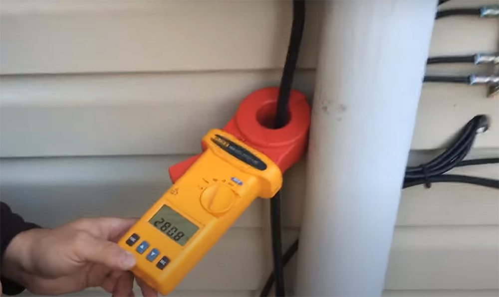
After you have made sure that both leads are in good contact, take a look at the multimeter display. The reading on the display is the ground resistance of the location you’re testing.
The acceptable resistance will depend on the specific application. For most applications, a ground resistance of under 5 ohms is considered to be good and for some it should be no higher than 1 ohm.
If the ground resistance is too high, it means that there is too much resistance between the ground and the equipment. This can lead to problems with electrical shock or fires. If you’re not sure what the acceptable range is for your application, consult an expert.
You should now have a good understanding of how to measure ground resistance with a multimeter. With this knowledge, you will be able to ensure that your equipment is properly grounded and safe from electrical hazards. [3], [13], [14], [15]
Check for Proper Socket Grounding
There is one last thing to check before using your multimeter to measure ground resistance and that is the socket grounding. The socket grounding can again be checked with a multimeter.
Set your multimeter to voltage mode
Next, take your multimeter and set it to AC voltage mode. This is important because you are going to be measuring the voltage drop between two points, and in order to get an accurate reading, your multimeter needs to be set to AC voltage mode. We recommend you to select the value of at least 200V for even more precision.
Confirm the power flowing through the outlets
After setting your multimeter to AC voltage mode, you will need to confirm that power is flowing through the outlets. Determine and note the voltage rating of the outlet that you are testing. Most outlets in the United States are rated for 120 volts.
You can check this by plugging a lamp or other appliance into the outlet and measuring the voltage between the hot and neutral wires with your multimeter. If there is no power flowing through the outlet, then you will not be able to measure any voltage.
Probe the outlets
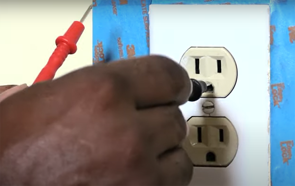
Now, take the probes of your multimeter and place them on the hot and neutral outlets. If everything is wired correctly, you should see the same value on the multimeter that you saw when you measured the voltage between the hot and neutral wires. The acceptable range for power flowing between both is from 120V to 240V. If you see a voltage lower than that, then there is a problem with your socket grounding and you need to fix it before proceeding. [13], [15]
FAQ
Can a multimeter test ground?
A multimeter can be used to measure the resistance of a ground by placing the probes on either side of the ground rod. The multimeter will display a reading in ohms.
To ensure an accurate reading, it is important that the multimeter is properly calibrated and that the probes are placed on clean, bare metal. If there is any paint or other material present, it can interfere with the reading.
What are the three most common methods of determining ground resistance?
There are three primary methods for determining ground resistance: the four-terminal method, the two-terminal method, and the three-pole method. All methods can measure ground resistance without requiring direct contact with the ground, which is essential for safety.
The four-terminal method is the most accurate of the three methods and involves measuring voltage between four electrodes placed in the ground.
How do you measure earthing resistance with a multimeter?
To measure earthing resistance with a multimeter, you will need to connect the multimeter leads to the earth electrode and ground rod. If you are using a digital multimeter, you will need to set it to the resistance measurement mode. Once you have done this, you can touch the probes to the earth electrode and ground rod. The reading on the screen will give you the resistance between these two points.
How many ohms is a good ground?
This is a difficult question to answer, as it depends on many factors such as the environment, equipment, and type of ground. Generally speaking, however, a good ground should have a resistance of less than 5 ohms.
If you are measuring the resistance of a ground rod with a multimeter, you will want to ensure that the meter is properly calibrated. Otherwise, you may get inaccurate readings. Additionally, make sure that the leads are securely connected to the multimeter and ground rod before taking your reading.
Can you test grounding with a multimeter?
Yes, you can test grounding with a multimeter. You will need to set the multimeter to the ohms setting and place the probes on the ground rod and on the test wire. If the reading is less than one, then the ground system is adequate. If the reading is less than 5 ohms, then the ground system is good. If the reading is greater than 55 ohms, then the ground system needs to be improved.
Useful Video: Earthing Multimeter Test
Conclusion
As you can see, measuring the ground resistance with a multimeter is not difficult, but there are some things you need to be aware of. Always make sure that the ground connection is secure and free from corrosion. Double check the condition of your equipment and the connections before taking any measurements. Keep in mind that the ground resistance measurement is only one part of ensuring electrical safety. If you’re working with live electrical circuits, always take proper precautions and follow all safety guidelines. Never work alone and always stay alert.
Now that you know how to measure ground resistance with a multimeter, you can use this knowledge to troubleshoot any problems that you may have with your electrical system. If you find that your ground resistance is too high, it may be necessary to replace some of your electrical components. However, if your ground resistance is within acceptable levels, then you can rest assured that your electrical system is safe and reliable. Thanks for reading! We hope this guide was helpful.
References:
- https://electrical-engineering-portal.com/good-grounding-system
- https://www.anixter.com/en_mx/resources/literature/wire-wisdom/conductor-resistance.html
- https://electrical-engineering-portal.com/what-is-a-good-ground-resistance-value
- https://blog.nvent.com/erico-what-is-soil-resistivity-and-how-does-it-affect-grounding/
- https://eepower.com/technical-articles/how-to-improve-resistance-to-ground/
- https://www.electricalampere.com/post/why-soil-conductivity-important-for-earthing
- https://www.researchgate.net/figure/Relationship-between-Soil-pH-and-Soil-ECdS-m_fig3_286451967
- https://electrical-engineering-portal.com/earthing-in-electrical-network-purpose-methods-and-measurement
- https://electrical-engineering-portal.com/earth-electrode-systems#resistance-electrode-encased
- https://www.apogeeweb.net/article/1422.html
- https://www.sciencedirect.com/topics/engineering/probe-resistance
- https://www.trenchlesspedia.com/definition/4145/wenner-4-point-test-method-soil-resistivity
- https://electrouniversity.com/how-to-measure-ground-resistance-with-a-multimeter/
- https://www.hunker.com/12002231/how-to-use-an-ohmmeter-to-measure-ground-resistance
- https://www.wikihow.com/Check-Earthing-at-Home