Are you curious about one of the most powerful tools for measuring electrical signals? Someone who isn’t familiar with circuits or oscilloscopes may be intimidated by them, but don’t let this stop you from exploring your potential in electronics. In this beginner’s guide, we’ll explain how to connect an oscilloscope to a circuit so that you can measure and compare voltage levels over time. We’ll cover why an oscilloscope is important, what features to look for when selecting one, and the step-by-step process of connecting it properly. Whether you’re just getting started with learning electronics or are looking to brush up on existing knowledge, understanding how to use an oscilloscope will open up countless possibilities for creating projects and experiments!
How Do You Connect an Oscilloscope?
Connecting an oscilloscope to a circuit is not difficult, but it does require precision. The first step is to identify which type of oscilloscope you are using as the connection will vary depending on the model. Once you have identified your oscilloscope, obtain the appropriate cables and probes for connecting to your circuit.
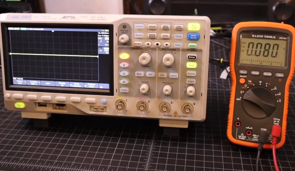
If needed, adjust your settings according to your specific needs such as triggering levels, time base range, voltage range and any other desired features. Some models may require special software installation in order for certain functions to be available (such as waveform capturing). Once everything is connected, you can begin testing your circuit with the oscilloscope by applying the appropriate voltage or signal. [1]
Your oscilloscope should then display the waveform of your circuit, which will provide visual feedback about its performance and help you identify any potential issues with it. With patience and practice, connecting an oscilloscope to a circuit can become second nature in no time!
What Is An Oscilloscope Used For?
While there are many uses for oscilloscopes, they are most often found in laboratories where engineers or technicians need to understand how certain parts of a circuit interact with one another. In addition to providing detailed information about the behavior of a given signal or waveform, oscilloscopes also allow users to measure frequency and amplitude of signals. This makes them essential tools for analyzing digital systems.
Once connected, oscilloscopes can be used for a variety of purposes. Engineers may use them to identify problems with their circuits by viewing the waveforms generated under different conditions. Technicians might use them to troubleshoot and diagnose equipment failures or malfunctions. Scientists may use them to study and understand complex signals and waves being generated in nature or other physical systems. Finally, hobbyists often turn to oscilloscopes when trying to build their own projects, as they are perfect tools for diagnosing any issues that arise during the process.
What Are The Different Types Of Oscilloscope?
Analog Oscilloscopes
These are the oldest type of oscilloscope, and they use a cathode ray tube (CRT) to display an analog waveform. Analog oscilloscopes are useful for observing the amplitude, frequency, and phase characteristics of electrical signals.
Digital Oscilloscopes
Digital oscilloscopes are more modern than their analog counterparts and offer a number of advantages such as higher resolution displays, easier data storage capabilities, and the ability to perform Fourier analysis on captured waveforms. Digital oscilloscopes also allow users to measure frequency response, distortion levels, harmonic content, rise times and fall times with greater accuracy than is possible with an analog scope. [2]
USB Oscilloscopes
USB oscilloscopes are relatively new tools that allow users to connect their oscilloscope directly to a computer’s USB port. This type of device eliminates the need for a separate power supply and makes it easy to view waveforms, capture images, analyze data, and store results on a PC.
Handheld Oscilloscopes
These are highly portable oscilloscopes that can be used to measure various electrical signals in the field. Handheld oscilloscopes typically have smaller displays than standard benchtop models, but offer the convenience of portability and low cost. They are often used by technicians for troubleshooting and inspection tasks.
How To Use An Oscilloscope To Measure Voltage?
Once you have connected your oscilloscope to a circuit, you can use it to measure voltage. To do this, connect the probe of the oscilloscope to one point in the circuit and ground it at another point. You should then be able to see a waveform on the screen. The peak-to-peak value of this waveform is equal to the voltage across that portion of the circuit. [3]
You can also measure voltage using an AC coupling setting on some digital storage oscilloscopes (DSOs). This helps eliminate any DC offset present in the signal being measured and lets you measure AC voltages more accurately.
To use an AC coupling setting, select it in the oscilloscope’s setup menu and set the scope’s vertical sensitivity to the proper value. Then, connect the probe of the oscilloscope to one point in the circuit and ground it at another point. The voltage across that portion of the circuit should be displayed on the screen as a waveform.
Finally, you can measure frequency with an oscilloscope by setting up a trigger level for your signal and observing how often it is reached. This allows you to accurately determine how fast your signal is changing, which can give important information about its behavior. To set up a trigger level, use your oscilloscope’s menu options to adjust both the trigger mode and threshold level until you get consistent readings.
By following these steps, you can easily use an oscilloscope to measure voltage, AC coupling, and frequency in a circuit. This can be a handy tool for troubleshooting electrical problems or simply getting an overview of the behavior of a complex circuit. With some practice, you’ll be able to get fast and accurate readings with your oscilloscope.
How to Calculate Frequency from an Oscilloscope?
Once you have connected your oscilloscope to a circuit, you can measure the frequency of a signal using the oscilloscope. Before attempting to calculate the frequency, ensure that the amplitude and DC offset of the signal are adjusted correctly.
To calculate frequency:
- Set up your oscilloscope settings by choosing a triggering source and setting up its parameters such as type of trigger (edge, width, etc.).
- Adjust the vertical scale so that one division represents one cycle of waveform.
- Measure time for one cycle of waveform with cursors; alternatively, you can use measurements options provided in the ‘measure’ menu in most modern digital storage oscilloscopes (DSO).
- Calculate the frequency by dividing 1/time period.
- If you need to convert Hz (Hertz) into KHz (Kilohertz), MHz (Megahertz) or GHz (Gigahertz), use multiplication or division as per the conversion factor.
- To measure a signal with higher frequency, choose an appropriate sampling rate and record length on your oscilloscope settings.
- Once you have measured the frequency successfully, adjust the triggering level, delay and amplitude of the waveform for further analysis.
By understanding how to connect and calculate frequency with an oscilloscope, engineers can accurately test electronic circuits and diagnose problems quickly. [4]
What Is A Division On An Oscilloscope?
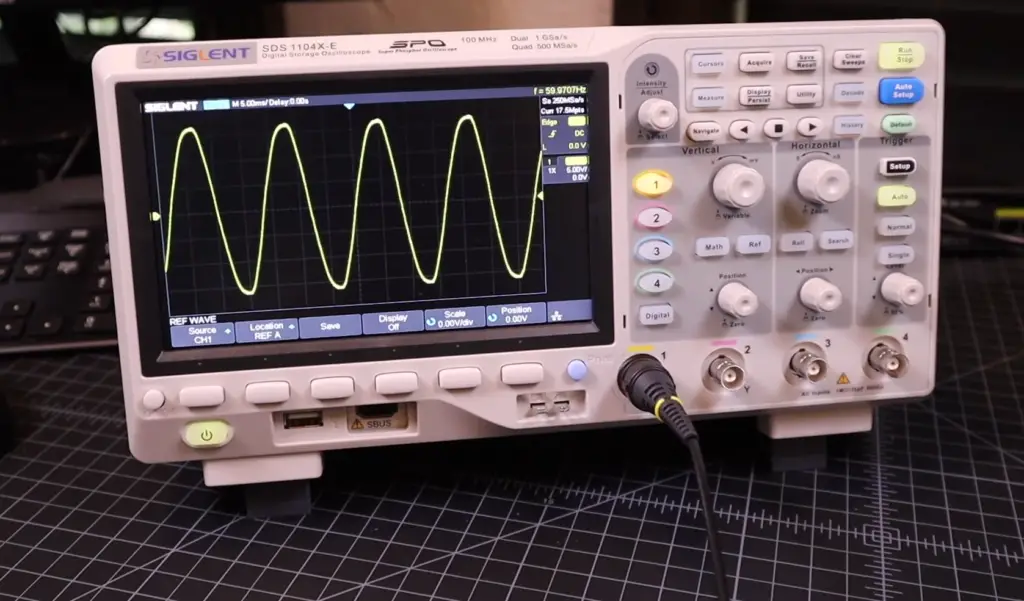
A horizontal division (also known as the x-axis) measures time while a vertical division (also known as the y-axis) measures voltage. When connecting an oscilloscope to a circuit, it is important to set both axes correctly so accurate readings can be taken from the circuit. The readout of an oscilloscope includes the number of divisions across which a signal spans and its amplitude or height in divisions. This information will help you understand what your circuit is doing in real-time.
To set up properly, make sure there are 10 divisions per cycle for the waveform being displayed, then adjust gain or volts/div settings until only one cycle is visible. After setting the volts/div and time base, you can then adjust the horizontal position control (HORIZ POS) to center the waveform on the screen. This will help ensure accurate readings of amplitude, period, frequency and other characteristics of a signal.
Finally, use the oscilloscope’s vertical and horizontal position controls to move around and explore features of your circuit or device being tested. You can pan across different areas of the display to observe any changes in behavior as well as zoom in for more detail. With these tools at your disposal you are now ready to connect an oscilloscope to a circuit! [5]
How Can An Oscilloscope Be Used to Test Circuits?
An oscilloscope is a powerful tool that can be used to measure and analyze the performance of electrical circuits. It works by displaying an amplified signal on a screen, which allows engineers to get detailed information about the circuit’s behavior. With an oscilloscope, it’s possible to quickly see voltage variations across components, as well as any changes in frequency or other parameters over time. This makes it ideal for troubleshooting circuits and determining where problems might lie.
By connecting an oscilloscope to a circuit, it’s possible to measure certain values such as voltages and frequencies at specific points within the system. This provides valuable insights into how components are working individually and how they may interact when combined in a larger circuit. [6]
What is an Oscilloscope Trigger?
An oscilloscope trigger is a control found on most modern digital oscilloscopes. It is used to activate the scope’s TDR (time-domain reflectometry) circuitry, allowing the device to measure and display changes in voltage over time more accurately. The trigger can be set to detect various conditions, such as when a signal crosses a certain threshold or when a specific pulse occurs. This level of control allows for analysis of data that would otherwise be difficult or impossible with an analog ‘scope.
When setting up the trigger, it is important to take into account the frequency of the signal being displayed and any potential noise sources in order to ensure accurate results. With proper use, an oscilloscope trigger can provide invaluable insight into the behavior of a circuit. It can be used to evaluate design elements such as power supply stability, signal integrity, and more.
What is Oscilloscope Gain?
Oscilloscope gain is a measure of how much an oscilloscope amplifies the input signal it receives. The gain setting on an oscilloscope directly affects the display of signals and waveforms on its screen. It can be set to provide either more or less amplification, depending on the desired effect for the signal being observed. Increasing the gain will open up smaller amplitude signals, while decreasing it will reduce clipping and distortion from too-large signals. When connecting an oscilloscope to a circuit, adjusting the appropriate gain setting is essential for obtaining accurate readings.
How Many Signals Can An Oscilloscope Display At Once?
An oscilloscope is a versatile instrument used to measure voltage signals over time, or waveforms. It can be used to detect electrical faults in circuits and troubleshoot problems by displaying multiple signals at once. The number of signals an oscilloscope can display simultaneously depends on the type of oscilloscope and its specifications. Generally, an entry-level oscilloscope may be able to display two input channels, while more advanced models may have four or more channels available for simultaneous use.
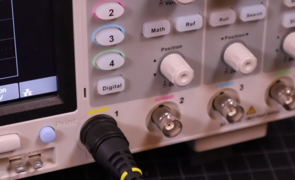
When connecting multiple signals to an oscilloscope, it’s important to remember that you cannot exceed the maximum number of channels as indicated in the device’s specifications. It is also important to ensure that all of your probes are designed for use with your particular model of oscilloscope. Each probe will have its own set of safety and performance specifications, so it is important to check the specs for your model before connecting them.
Once you have chosen the correct probes for your oscilloscope, the next step is connecting them to the desired signals. An oscilloscope usually has two sets of inputs: one for a common ground (GND) connection and one for the signal being measured. Make sure that all of your probes are connected properly and securely before powering on the device. Now you can view multiple signals at once on your oscilloscope’s screen! [7]
What Is The Time Base On An Oscilloscope?
The time base on an oscilloscope is the speed at which a trace moves across the screen. It’s typically measured in seconds or microseconds per division and can be adjusted to increase or decrease the speed at which a trace moves across the display. The purpose of the time base setting is to create a visual representation of what’s happening in your circuit over time. By understanding how to use and adjust this feature, you can easily analyze waveforms to get a better understanding of your circuit’s behavior.
To adjust the time base, begin by connecting your oscilloscope probe directly into your circuit using any standard clip lead or coaxial cable. Be sure that it is securely connected so that no potential noise signals are introduced. Once your probe is connected, press the “Time Base” button on the oscilloscope to open up the time base menu. From here, you can select from a range of options that will adjust how quickly or slowly a trace moves across the display.
Once you have made your selection, press the “Run/Stop” button to begin viewing data in real-time. Your oscilloscope should now be displaying waveforms in a manner that allows for easy analysis and comparison. With some practice and patience, it’s easy to learn how to use this feature effectively so that you can get accurate results from your circuit measurements.
FAQ
What do you connect an oscilloscope to?
An oscilloscope can be connected to an electronic circuit or device for testing and debugging. The most common connection is between the oscilloscope’s probes and the two points of a circuit that you want to measure, such as a voltage or current source. Additionally, some oscilloscopes allow for digital connections so that data from a computer can be analyzed visually on an oscilloscope screen.
How do I connect my oscilloscope?
To connect your oscilloscope to your circuit, you will need to ensure the correct type of connector is in use. Depending on the model of your scope, it may require BNC or banana plug connectors when attaching its test probes, while others may use SMA (SubMiniature A) connectors. Once the connectors are in place, the probes can be clipped onto the circuit where measurements are to be taken. It is recommended that you consult your oscilloscope’s user manual for information on specific connection instructions for your device. Additionally, most oscilloscopes come with a range of accessories such as ground clips and leads that may need to be used when performing measurements or tests.
Are there any safety precautions I should take when connecting an oscilloscope?
Yes. It is important to always keep in mind that an oscilloscope is connected directly to a live circuit and therefore poses the risk of electric shock if handled improperly. Therefore, it is important to follow all manufacturer instructions carefully when setting up your oscilloscope. Also, make sure never to use force when connecting or disconnecting your scope, as this may damage the connectors. Additionally, make sure all connections are secure and if using banana plugs, they should be fully inserted into the sockets before powering up your oscilloscope. Lastly, always ensure that you are wearing safety glasses and insulated gloves when working with an oscilloscope.
Do I need additional equipment to use an oscilloscope?
Yes, some other pieces of equipment may be required depending on what measurements or tests you plan to perform with an oscilloscope. For example, you may need an external power supply or signal generator in order to run tests on a circuit. Additionally, accessories such as probes and clips will likely be necessary for making accurate measurements and readings from the device itself. It is important to refer to your scope’s user manual for details on additional equipment and accessories that may be required.
Can an oscilloscope measure other signals?
Yes, in addition to measuring voltages and currents, an oscilloscope can also measure other waveforms such as those of sound or radio frequencies. This is especially useful when testing audio circuits or components, where the waveform generated by a speaker or microphone needs to be observed. Similarly, if you are working with RF (Radio Frequency) devices, then having a scope capable of measuring these frequencies can be invaluable in debugging any issues with these components.
How do you capture current from an oscilloscope?
Capturing current from an oscilloscope requires a different method depending on the type of circuit you’re testing. For a low-power, low-voltage direct current (DC) circuit, connecting the negative lead of your oscilloscope probe to ground is sufficient. However, this method will not work with an alternating current (AC) or high voltage DC circuit as it will most likely overload the input impedance of your oscilloscope. For AC circuits and higher voltage DC circuits, you need to use a series resistor in order to limit the current into your oscilloscope and prevent damage. The correct value for this resistor depends on your exact setup, so it is best to consult an electronics engineer or other technical expert before attempting this. Once the resistor is in place, connect the oscilloscope probe’s positive lead to the circuit you want to measure and its negative lead to one terminal of the series resistor. Connect the other terminal of the series resistor to ground.
Useful Video: Oscilloscope Tutorial (Basics 101)
Conclusion
Connecting an oscilloscope to a circuit is an important part of troubleshooting and understanding the behavior of circuits. It allows users to view voltage waveforms in real-time, giving valuable insights into the operation of their design. The basic steps include connecting probes to signal points, setting up the parameters on the oscilloscope for proper measurement, and displaying the waveform. While there are many configurations that may require additional steps, these basics should get you started with most scenarios. Understanding how to connect an oscilloscope will be helpful in any electronics project or experiment.
References
- https://www.circuitsgallery.com/how-to-connect-an-oscilloscope-to-a-circuit/
- https://learn.sparkfun.com/tutorials/how-to-use-an-oscilloscope/all
- https://www.retrotechlab.com/how-to-connect-an-oscilloscope-to-a-circuit/
- https://www.tek.com/en/documents/primer/setting-and-using-oscilloscope
- https://www.instructables.com/Oscilloscope-How-To/
- https://www.build-electronic-circuits.com/oscilloscope/
- https://www.circuitbasics.com/what-are-oscilloscopes/






Leave a Reply