
Have you ever wondered how to accurately measure an inductance? Measuring the electrical characteristics of components can be an important part of any electronics project. Inductance is a key factor when it comes to determining the integrity and operation of components, making its measurement crucial in order to ensure that things will run as expected. While this task used to be tedious and time-consuming, oscilloscope technology now makes it easier than ever before! In this blog post, we’ll walk you through step by step on how to measure inductance with your oscilloscope using waveforms – from preparing the test circuit setup and initializing probes; all the way through what each displayed value actually means. So if you’re interested in learning how measuring inductance with your oscilloscope offers not only convenience but also valuable insight into your design – read on!
What Is An Oscilloscope?
An oscilloscope has two inputs — one for measuring voltage (V) and the other for measuring time (T). The combination of these two measurements allows us to measure various parameters such as frequency, amplitude, period, and phase. [1]
How To Measure Inductance With An Oscilloscope?
Resonant Frequency Method
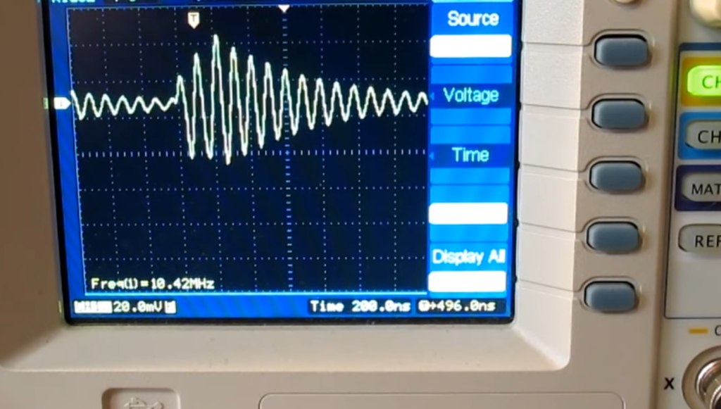
It is common to use the Resonant Frequency Method with an oscilloscope to measure inductance. This method involves applying a sinusoidal signal to the inductor and observing its response on the oscilloscope. The frequency at which the applied signal produces a maximum amplitude across the inductor is known as its resonant frequency, and can be used to calculate its value of inductance.
To measure an inductor’s resonant frequency with an oscilloscope, first connect it in series with a capacitor; this will form an LC (inductor-capacitor) tank circuit. Next, apply a small alternating voltage to the circuit and observe it on the oscilloscope screen. Slowly increase the frequency of the signal until you observe a peak in the signal. This will be the resonance frequency of your inductor, which can be used to calculate its inductance.
The formula for calculating inductance is: L = 1 / (2 * π * f_res^2 * C) where L is the inductance value, π is pi, f_res is the resonant frequency, and C is the capacitance value. Once you have calculated your inductor’s value of inductance using this formula, you can use it in other applications or experiments as needed. It should be noted that while this method works well for measuring small-valued inductors (< 10μH), it may not be accurate for measuring larger values of inductance. [2]
Using A Resistor Of Known Value
Inductance can be measured by using a resistor of known value. This method relies on the fact that inductors have an impedance (resistance and reactance) that is proportional to frequency. Since an oscilloscope has a built-in function generator, it can easily generate signals at different frequencies, allowing us to measure the impedance of the inductor at various frequencies. The resistance of the resistor can be used as a reference point for measuring the inductance.
First, connect one lead of the resistor to ground and another lead to the input channel on the oscilloscope. Then connect one end of the inductor to ground and another end to the output channel on the oscilloscope. Using a sine wave generator inbuilt in an oscilloscope, generate a waveform with different frequency. The resulting waveform will be shifted due to inductance of the coil and this shift can be used to calculate the inductance of the coil.
To calculate the inductance, use the following formula: L = (X/2πfR), where X is the phase angle between input voltage and output current, f is frequency in Hertz, and R is resistance in Ohms. Through this formula you can accurately measure the value of inductance with an oscilloscope.
By using this method, one can easily measure inductance without any external instruments or meters. It is a fast, simple and reliable way to measure inductance for hobbyists as well as professionals.
Using Voltage-Current Slope Method
The voltage-current slope method is one of the simplest and most efficient ways to measure inductance with an oscilloscope. This method involves measuring the voltage across a resistor when it is subjected to a varying current. The slope of this curve is then used to calculate the value of inductance in henrys (H). To begin, connect a resistor in series with an inductor. Then, apply an AC signal source to both components, providing current that varies over time. Use a probe connected to your oscilloscope to measure the voltage across the resistor at various times throughout its cycle. Record all of these points by writing down their corresponding voltages and times.
Once you have all your data points recorded, plot them on a graph and draw a line of best fit that passes through the points. The slope of this line will give you the inductance in henrys. Using this method, you can easily measure the inductance of any component with an oscilloscope. Just make sure you are using a resistor with low enough resistance to avoid saturating your circuit, or else your measurements may not be accurate. [3]
How Do You Measure Inductance With A Multimeter?
Measuring inductance with a multimeter is relatively simple and can be done in just a few steps. First, set the multimeter to measure resistance (Ohms). Next, place one probe of the multimeter on each end of the inductor being tested. Once both probes are in place, you should see a reading on the display that indicates the inductance value for your component. It is important to note that most multimeters do not automatically calculate this value; instead, you must use an equation or some other method to determine it.
To help figure out the exact values of inductance, many modern digital multimeters offer additional functionality such as frequency measurement capability which can be used to calculate capacitance and inductance values more accurately. Additionally, some multimeters also offer a “diode test” which can be used to determine the forward and reverse voltages of an inductor.
Overall, measuring inductance with a multimeter is simple and provides all the necessary information needed to make sure your components are functioning properly. With just a few steps and the right equipment, you can easily measure the inductance of any component in your circuit with accuracy and confidence.
How Do You Measure Inductance Of A Coil With An Oscilloscope?
Measuring the inductance of a coil with an oscilloscope is fairly straightforward. First, you will need to connect the coil to your scope and set up the parameters for measurement. Next, you will use an AC voltage source connected in series with the coil to induce an alternating current (AC) through it. The oscilloscope should be set up to measure both voltage and current simultaneously at a frequency of 1kHz or higher. Once all the necessary connections are made, turn on the AC power source and note down the measured values displayed on your oscilloscope’s screen. [4]
The next step is to calculate the inductance of your coil using Ohm’s Law: L = V / I x F, where L is the inductance in Henries, V is the voltage measured across the coil and I is the current through it. The frequency (F) should be known beforehand from your AC power source. Once you have calculated the inductance of your coil, you can confirm its value by repeating steps one to four with a different AC frequency and measuring any change in readings. Finally, you will want to document all of your results and keep them for future reference. [5]
By using an oscilloscope to measure inductance, you can quickly determine the value of a coil without having to resort to expensive laboratory equipment or time-consuming manual calculations.
Uses Of Inductors
Inductors are used in a variety of applications ranging from simple signal conditioning circuits to more complex applications such as energy conversion and radio frequency signal processing. They can be used to filter unwanted frequencies, reject noise, and stabilize power supply voltages. In motor control systems, they are used for speed control, current regulation, and over-current protection. Inductors are also important components in many electrical machines; electric motors and generators rely on them to produce torque or generate electricity from mechanical motion. [6]
FAQ
How do you measure inductance?
Measuring inductance is possible with an oscilloscope. The process involves connecting one end of a known resistor to the oscilloscope’s ground and the other end into a high-impedance source. Once the circuit is complete, you can adjust the voltage settings on the resistor so that an AC current flows through it. By measuring the frequency of this AC current, and then applying Ohm’s law, you can calculate the inductance of your circuit. This process works best with a higher voltage reading so it is recommended to use a power supply with adjustable voltages instead of just using battery power for this task.
How does an LCR measure inductance?
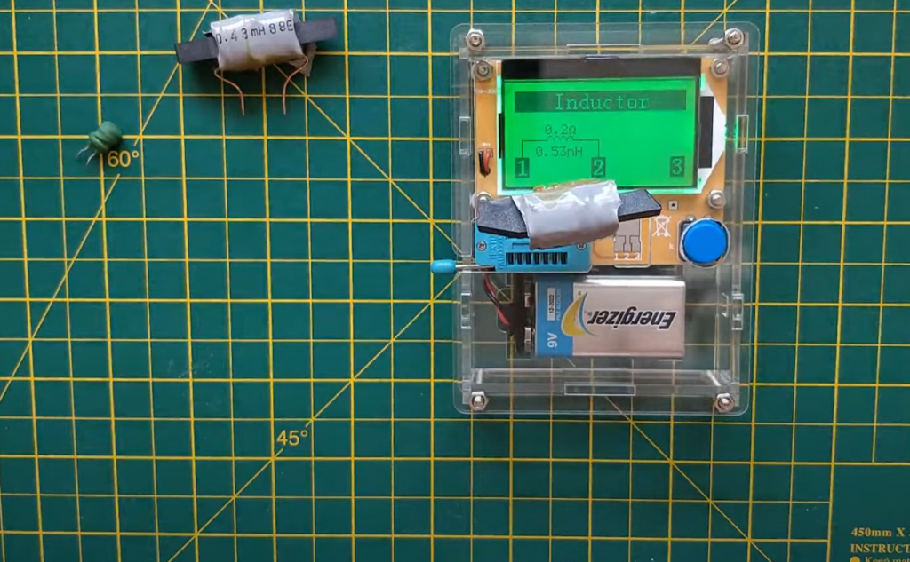
An LCR, or Inductance-Capacitance-Resistance meter, is a specialized tool that measures the inductance of a component by analyzing its frequency response. It works similarly to an oscilloscope in that it is connected across the two terminals of a resistor and then the voltage is adjusted to create an AC current flow through it. The LCR then measures the frequency and phase shift of this AC current and uses these values to calculate the inductance of your component. An LCR can also measure capacitance and resistance as well, making it a great tool for troubleshooting any type of circuit.
How do you measure inductance without an oscilloscope?
Measuring inductance without an oscilloscope requires the use of a multimeter. The most common type, the analog multimeter (also known as an AVO meter), can be used to measure inductance by setting the range switch to “INDUCTANCE” and connecting it in accordance with your device’s instructions for measuring resistance or capacitance. If you are using a digital multimeter (DMM), set the range switch to read “L”and connect it as instructed. In both cases, make sure that you set the appropriate scale to measure in microhenries (mH). To get accurate results, use a test lead with low resistance and use high-impedance when taking measurements. Additionally, if your multimeter does not have an inductance range, you can still measure inductance by using the “resistance” mode and converting with the appropriate formulas.
How do you measure an inductor with a multimeter?
You can use a multimeter to measure the inductance of an inductor in two steps. First, set your multimeter to the ohms setting and connect it between the leads (or terminals) of the inductor. Then press the measurement button on the multimeter and note down its reading. This will give you a resistance value, which is usually very low for an inductor. Once you have this resistance value, plug in your multimeter into the AC setting and then use it to measure the peak voltage across your resistor at different frequencies. By plotting these values, you should be able to determine the inductance of your inductor by measuring how much voltage is required to generate a certain amount of current through it.
What are the cons of measuring inductance with an oscilloscope?
One of the main drawbacks of using an oscilloscope to measure inductance is that the accuracy of readings can be affected by external factors, such as temperature, humidity and even the quality of the conductors. Additionally, an oscilloscope cannot directly measure inductance; it must rely on other instruments or equations to calculate results. This makes direct comparison with standard values difficult. Furthermore, oscilloscopes are limited to reading low frequencies and have a minimum sensitivity limit for measuring very small inductances. Therefore, they may not be suitable for measuring very high or low frequency signals without additional equipment. Finally, if multiple components are connected in parallel with varying impedances, then correct measurements may be impossible to obtain without more advanced instrumentation.
What are the pros of measuring inductance with an oscilloscope?
Using an oscilloscope for measuring inductance offers several advantages. Firstly, the accuracy and precision of the measurements are improved compared to a multimeter. Secondly, you can quickly analyze larger inductors without worrying about having too many components or wires connected to your circuit. Thirdly, the oscilloscope allows you to easily see small changes in waveforms over time so you can more accurately identify problems with circuits and find out how different components interact with each other. Additionally, it is easier than ever to measure impedances and frequencies due to the automated functions within the oscilloscope software. Finally, using an oscilloscope gives you more flexibility when analyzing complex circuits because you can observe multiple signals at once and compare them against one another or against fixed reference values. As a result, diagnosing issues with circuits is made easier and faster.
How can Q meter can be used to measure inductance?
Q meter is a device used to measure the quality factor of an inductor. It measures the ratio between the reactance and resistance of an inductor, which gives you its Q-value or Quality Factor. This value is directly related to the inductance of the component. To use a Q-meter, it needs to be connected in series with the component being tested through its two terminals. A signal generator is then used to send a signal at a known frequency into the circuit and this causes a resonance in the coil, allowing us to determine its characteristic frequency by measuring voltage output on an oscilloscope. The higher voltages you get indicate higher inductance values for your component since they represent more power stored inside it due to increased levels of inductance. The Q-meter can also be used to measure the power factor of the component which is related to its impedance and capacity. With this data, you can make more informed decisions about your circuits or components.
Useful Video: Measuring inductance with an oscilloscope and signal generator
Conclusion
Measuring inductance with an oscilloscope is a simple and reliable method that gives accurate readings. It does not require any special components or devices, making it a cost-effective solution for measuring inductance in electronic circuits. The technique only requires basic knowledge of the oscilloscope display and operation, as well as some knowledge of electrical engineering fundamentals. With this easy technique, engineers can quickly determine the value of inductors in their designs without using costly specialized equipment.
References
- https://www.testandmeasurementtips.com/how-to-measure-inductance/
- https://www.circuitsgallery.com/measuring-inductance-with-oscilloscope/
- https://www.wikihow.com/Measure-Inductance
- https://www.tek.com/en/documents/application-note/capacitance-and-inductance-measurements-using-oscilloscope-and-function-ge
- https://saving.em.keysight.com/en/knowledge/guides/signal-generator-buying-guide/how-to-measure-inductance-with-oscilloscope-and-signal-generator
- https://www.dos4ever.com/inductor/inductor.html