

A voltmeter, a vital instrument in the world of electronics, serves the fundamental purpose of measuring voltage or potential difference between two points in an electrical circuit. Understanding how to connect a voltmeter to a circuit is essential for accurate voltage measurements and efficient troubleshooting of electrical systems. Connecting a voltmeter requires careful consideration of the circuit’s configuration and the type of voltmeter being used.
In this article, we will delve into the intricacies of how a voltmeter is connected in a circuit, exploring both the parallel and series connection methods. We will examine the distinct characteristics of analog and digital voltmeters, highlighting their specific connection requirements. Moreover, we will emphasize the significance of selecting the appropriate voltage range and the precautions to be taken to ensure safe and reliable voltage measurements.
By the end of this article, readers will gain a comprehensive understanding of the various aspects involved in connecting a voltmeter to a circuit and be equipped with the knowledge to effectively use this essential tool in their electrical endeavors.
What Is A Voltmeter?
How Does It Work?
The primary function of a voltmeter is to measure potential differences, or voltage, across two points in a circuit. It achieves this by connecting its two probes across the points of interest. When connected, the voltmeter creates a parallel path with very high resistance, allowing only a negligible current to pass through the instrument.
The voltage across the voltmeter is proportional to the potential difference between its probes. Modern voltmeters are typically digital, employing analog-to-digital converters to provide accurate voltage readings displayed on an LCD or LED screen. Analog voltmeters, on the other hand, use a pointer on a scale to indicate the voltage.
Types of Voltmeters:
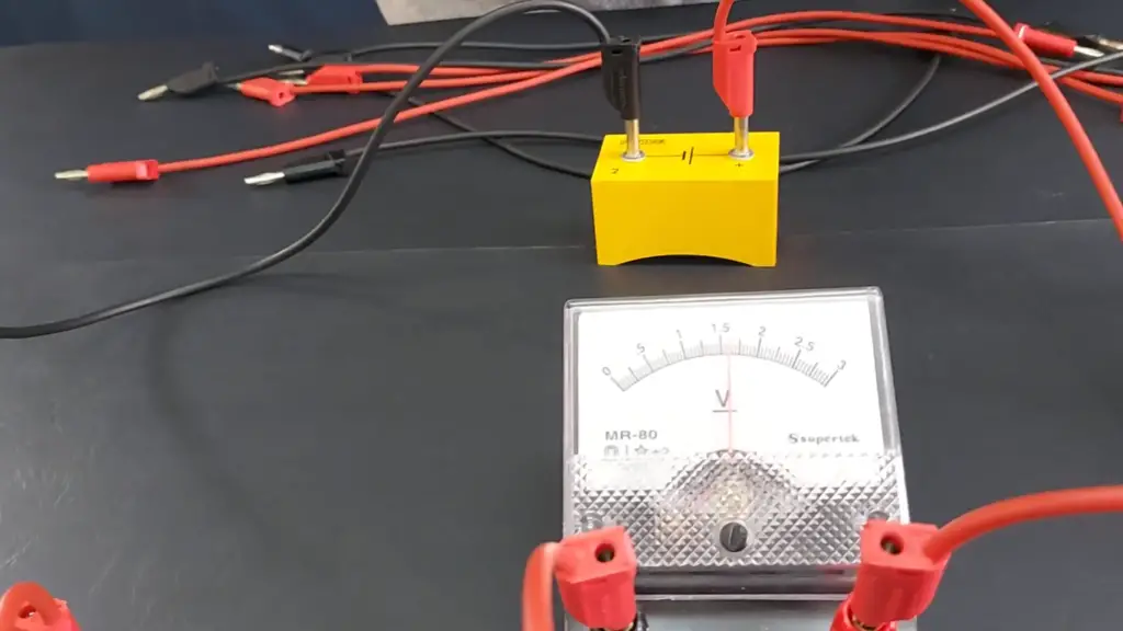
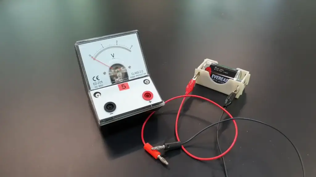
- Analog Voltmeter: These traditional voltmeters use a moving coil or moving iron mechanism. As the voltage varies, the movement of the coil or iron changes, resulting in the pointer’s deflection, indicating the measured voltage. While they are less accurate than digital voltmeters, analog meters are still valued for their simplicity and reliability in certain applications;
- Digital Voltmeter (DVM): Digital voltmeters offer precise readings with numerical displays. They utilize digital circuitry to convert the analog voltage input into digital form, making them more accurate and versatile than analog voltmeters. DVMs may be handheld or integrated into larger measuring systems;
- Analog-to-Digital Converter (ADC): This type of voltmeter is commonly found in microcontrollers and other digital systems. It uses an ADC, which converts the analog voltage into a digital signal that can be processed by the microcontroller. The results are typically displayed on a screen or sent to a computer for further analysis;
Importance of Voltmeter
Voltmeters are essential tools for electricians, engineers, and hobbyists working with electrical systems. They enable precise measurements of voltage, aiding in diagnosing circuit malfunctions, ensuring the correct operation of electronic devices, and maintaining the safety of electrical installations.
By measuring voltage, technicians can identify potential issues such as overvoltage, under-voltage, or voltage fluctuations, which might otherwise damage sensitive electronics or compromise the performance of machinery.
Connecting a Voltmeter:
Parallel Connection of a Voltmeter
The most common method of connecting a voltmeter is in parallel with the circuit element or points where the voltage is to be measured. This arrangement is known as “parallel connection” or “parallel mode” [2].
Steps to Connect a Voltmeter in Parallel:
- Prepare the Circuit: Before connecting the voltmeter, ensure that the circuit is powered off, and any relevant safety precautions are taken. Identify the two points across which you want to measure the voltage;
- Connect the Voltmeter: Take the voltmeter and set it to the appropriate voltage range that covers the expected voltage in the circuit. Then, connect the voltmeter’s positive (red) probe to the point with higher potential and the negative (black) probe to the point with lower potential;
- Reading the Voltage: Once the voltmeter is connected, you can turn on the circuit and read the voltage displayed on the voltmeter’s screen. Ensure to read the measurement units (usually volts, V) to have the correct value;
The parallel connection of a voltmeter provides an accurate measurement of the voltage across the specific component or points in the circuit. It is standard practice for measuring voltage in most scenarios, whether in household electronics, automotive systems, or industrial applications.
If a Voltmeter is Connected in Series
Unlike the parallel connection, connecting a voltmeter in series with a circuit requires a different approach. This connection method is known as “series connection” or “series mode”.
Steps to Connect a Voltmeter in Series:
- Prepare the Circuit: As always, make sure the circuit is powered off and any safety measures are in place. Identify the circuit element whose voltage you want to measure;
- Interruption of the Circuit: To connect a voltmeter in series, you must interrupt the circuit at the point where you want to measure the voltage. This means cutting the circuit and placing the voltmeter between the two cut ends;
- Connect the Voltmeter: Once the circuit is interrupted, connect the voltmeter’s positive probe to one cut end and the negative probe to the other cut end, essentially bridging the gap with the voltmeter;
- Reading the Voltage: With the voltmeter in series, you can turn on the circuit and read the voltage displayed on the voltmeter’s screen;
Advantages and Disadvantages of Series Connection of a Voltmeter
While the parallel connection is the standard and widely used method, there are specific scenarios where the series connection may be preferred or necessary:
Advantages:
- High-Resistance Components: In circuits containing high-resistance components, using a parallel voltmeter might cause a significant voltage drop across the component, leading to inaccurate measurements. In such cases, a series voltmeter would be more suitable as it has negligible impact on the circuit;
- Measurement of Current: Sometimes, when measuring voltage in circuits with substantial current flow, a parallel connection can be impractical or unsafe. Using a series voltmeter allows for measuring voltage without breaking the circuit;
Disadvantages:
- Circuit Interruption: The series connection requires cutting the circuit to insert the voltmeter, which can be inconvenient and might disturb the circuit’s functionality;
- Complexity: The series connection method introduces additional complexities, especially in circuits with multiple voltage measurements, making it more challenging to set up;
Safety Precautions When Connecting the Voltmeter
Connecting a voltmeter to measure voltage in an electrical circuit is a common task for engineers, electricians, and hobbyists. While the process may seem straightforward, it is essential to prioritize safety to avoid accidents, electrical hazards, and equipment damage. Whether you are using a digital or analog voltmeter, adhering to safety precautions is crucial [3].
Here are some essential safety guidelines to follow when connecting a voltmeter:
1. Turn Off the Power
Before connecting the voltmeter, always ensure that the power to the circuit is turned off. This precaution prevents electric shocks and protects both you and the equipment. Double-check that the circuit is de-energized by using a non-contact voltage tester before proceeding with the voltmeter connection.
2. Inspect the Voltmeter
Inspect the voltmeter for any signs of damage or wear before use. Check the probes, cables, and display for any issues. Using a faulty voltmeter can lead to inaccurate readings and potential safety hazards.
3. Use the Correct Range
Ensure that the voltmeter is set to the appropriate voltage range before connecting it to the circuit. Using the wrong range can result in overload and damage to the voltmeter. If unsure about the voltage range, start with the highest setting and gradually decrease it until you get a proper reading.
4. Parallel Connection
For most voltage measurements, use the parallel connection method by connecting the voltmeter in parallel with the circuit element or points of interest. This method minimizes circuit disturbance and ensures accurate readings without interrupting the circuit’s operation.
5. Avoid Overloading
Be mindful of the maximum voltage capacity of the voltmeter. Exceeding this limit can damage the instrument and pose safety risks. If the voltage in the circuit is unknown, start with a high-range setting and decrease it until an appropriate reading is obtained.
6. Watch for Short Circuits
During the connection process, be cautious not to create accidental short circuits. Short circuits can cause sparks, heat, and damage to both the circuit and the voltmeter. Ensure that the probes do not come into contact with each other or other conductive surfaces during the connection.
7. Wear Proper Safety Gear
When working with electrical circuits, it is advisable to wear appropriate personal protective equipment (PPE), such as insulated gloves and safety goggles. PPE provides an extra layer of protection against electrical shocks and potential hazards.
8. Keep the Area Dry
Working with electrical equipment in a damp or wet environment can increase the risk of electrical shock. Always ensure that the workspace is dry and free from any water or liquid.
9. Double-Check Connections
Before turning the power back on, double-check all the connections to ensure they are secure and properly connected. Loose connections can lead to inaccurate readings or cause the voltmeter to malfunction.
10. Work with a Buddy
Whenever possible, have someone else nearby while working with electrical circuits. In case of an emergency, having assistance readily available can be crucial.
Why Is the Voltage Same in Parallel Circuits?
In a parallel circuit, the voltage is the same across all the components connected in parallel. This characteristic is a fundamental principle of parallel circuits and can be explained by understanding how current flows in such a configuration.
Here’s why the voltage is the same in each parallel branch:
- Common Voltage Source: In a parallel circuit, all branches are connected to the same voltage source, such as a battery or power supply. Since the voltage source provides a constant potential difference across its terminals, this voltage is shared across all parallel branches;
- Potential Difference: Voltage is the measure of the potential difference between two points in a circuit. In a parallel configuration, all the components within each branch have the same voltage across their terminals as the voltage source. This is because the branches are directly connected to the same two points of the voltage source;
- Constant Voltage: As the voltage is the same across the components in each branch, it remains constant throughout the parallel circuit. Regardless of the number of branches or the components within them, the voltage remains unchanged;
- Voltage Division Rule: Another way to understand why the voltage is the same in parallel circuits is by applying the voltage division rule. According to this rule, in a parallel circuit, the voltage across each branch is the same as the voltage across the entire parallel combination. The voltage division is inversely proportional to the resistance of each branch: the higher the resistance of a branch, the lower the current flowing through it, but the voltage across it remains the same as that of the source [4];
How Does Voltmeter Measure the Potential Difference?
A voltmeter measures the potential difference (voltage) between two points in an electric circuit by utilizing the principle of electromotive force and the conversion of electrical energy into mechanical or digital indications. The inner workings of a voltmeter can vary depending on whether it is an analog or digital voltmeter.
Analog Voltmeter
An analog voltmeter typically uses a moving coil or moving iron mechanism to measure voltage. Here’s how it works:
- Moving Coil or Moving Iron: Inside the voltmeter, there is a coil of wire or a piece of iron that is free to move within the magnetic field of a permanent magnet;
- Voltage Application: When voltage is applied to the voltmeter by connecting its probes across the two points whose potential difference is to be measured, the voltage causes a current to flow through the coil or iron;
- Magnetic Effect: The current flowing through the coil or iron generates a magnetic field around it. This magnetic field interacts with the fixed permanent magnet, causing a torque (rotational force) to act on the coil or iron;
- Pointer Deflection: The torque causes the coil or iron to move, and this movement is mechanically translated into the rotation of a pointer on a scale;
- Scale Reading: The rotation of the pointer on the scale indicates the magnitude of the voltage being measured. The scale is calibrated to provide the voltage reading directly in volts (or millivolts) for the specific voltmeter [5];
Digital Voltmeter (DVM)
Digital voltmeters use electronic components and digital signal processing to measure voltage. Here’s how they work:
- Analog-to-Digital Conversion: When the probes of a digital voltmeter are connected across the two points, the voltage is first converted into an analog electrical signal;
- Analog Signal Conditioning: The analog signal is then conditioned and amplified to bring it to a suitable level for accurate conversion;
- Analog-to-Digital Converter (ADC): The conditioned analog signal is passed through an Analog-to-Digital Converter (ADC). The ADC converts the continuous analog signal into discrete digital values;
- Microcontroller/Processor: The digital values obtained from the ADC are processed by a microcontroller or digital processor;
- Display: The processed digital information is displayed on the voltmeter’s screen. The display provides the voltage reading directly in volts or other appropriate units;
The main advantage of digital voltmeters lies in their accuracy, versatility, and ease of reading. They can also offer additional features, such as auto-ranging (automatically selecting the appropriate voltage range), data logging, and connectivity to other devices for data transfer and analysis.
Both analog and digital voltmeters serve the same fundamental purpose of measuring voltage, but their underlying mechanisms for measuring and displaying the potential difference between two points in a circuit differ significantly. The choice between using an analog or digital voltmeter depends on the specific requirements of the application and the preferences of the user.
Why Does Voltmeter Have High Resistance?
A voltmeter has high resistance to ensure that it draws very little current from the circuit it is measuring. This characteristic is essential for accurate voltage measurements and to prevent any significant disruption to the circuit’s operation.
When a voltmeter is connected in parallel to measure voltage, it effectively creates an additional path for current to flow. If the voltmeter had low resistance, it would draw a substantial amount of current from the circuit, altering the voltage at the measurement points and causing inaccurate readings. This phenomenon is known as “loading” the circuit.
To avoid loading the circuit and obtain accurate voltage measurements, the voltmeter is designed with high resistance. By having a high resistance, the voltmeter draws only a negligible amount of current from the circuit. In an ideal voltmeter, the resistance would be infinite, so no current would flow through it at all. However, real-world voltmeters have a finite resistance, typically in the range of megaohms (millions of ohms).
According to Ohm’s law (V = I * R), with high resistance (R), even a small current (I) would result in a minimal voltage drop across the voltmeter (V) [6]. This voltage drop is so small that it can be neglected, and the voltmeter effectively measures the potential difference between the two points without causing any significant disturbance to the circuit.
It’s important to note that the high resistance of a voltmeter only applies when it is connected in parallel to measure voltage. When a voltmeter is connected in series, it would behave like a resistor in the circuit and alter the current flow, which is generally not desirable for voltage measurements. Therefore, voltmeters are designed to be used exclusively in parallel mode to maintain their high resistance and ensure accurate readings without affecting the circuit’s behavior.
How to Connect a Voltmeter In a Circuit To Measure The Potential Differences Between Two Points?
Connecting a voltmeter in a circuit to measure the potential difference between two points is a simple process. The voltmeter should be connected in parallel with the two points whose voltage you want to measure.
Note: Before proceeding, ensure that the circuit is powered off and any safety precautions are taken to avoid electrical hazards.
Here’s a step-by-step guide to connecting a voltmeter in parallel:
Step 1: Prepare the Circuit
Ensure that the power to the circuit is turned off, and if applicable, disconnect any power source. Identify the two points in the circuit between which you want to measure the potential difference (voltage).
Step 2: Set the Voltmeter
If you are using an analog voltmeter, ensure that the range selector switch is set to an appropriate voltage range that covers the expected voltage in the circuit. For digital voltmeters, no manual range setting is required as they typically auto-range.
Step 3: Connect the Voltmeter
Take the voltmeter’s probes and connect them in parallel across the two points whose voltage you want to measure. The positive (red) probe should be connected to the point with higher potential, and the negative (black) probe should be connected to the point with lower potential.
Step 4: Read the Voltage
Once the voltmeter is correctly connected in parallel, you can turn on the circuit or power source. The voltmeter should now display the voltage between the two points on its screen. Make sure to read the measurement units (usually volts, V) to have the correct value.
Step 5: Disconnect the Voltmeter
After you have obtained the voltage reading, turn off the circuit or disconnect the power source. Then, remove the probes from the circuit.
Step 6: Recheck Connections
Double-check all connections to ensure they are secure and properly connected before turning the circuit back on [7].
Tips to Improve the Accuracy of Voltmeter
Improving the accuracy of a voltmeter is crucial to obtain reliable voltage measurements in electrical circuits. Here are some tips to enhance the accuracy of a voltmeter:
- Calibration: Regularly calibrate the voltmeter to ensure its accuracy. Calibration involves comparing the voltmeter’s readings with a known standard or reference voltage. If any discrepancies are found, adjustments can be made to improve accuracy;
- Choose the Right Range: Select the appropriate voltage range on the voltmeter that best covers the expected voltage in the circuit. Using the correct range helps avoid overloading the voltmeter and ensures better accuracy;
- Use High-Quality Voltmeter: Invest in a high-quality voltmeter with a reputation for accurate measurements. Cheaper, low-quality voltmeters may introduce errors and inaccuracies;
- Avoid Parallax Errors: When reading an analog voltmeter with a scale and pointer, make sure to view the pointer directly from the front and at eye level to avoid parallax errors, which can lead to misinterpretation of the reading;
- Zero Adjustment: Some analog voltmeters have a zero-adjustment screw or knob. Use this adjustment to ensure the pointer is at zero when no voltage is applied. This helps to eliminate any offset error;
- Minimize Noise and Interference: Keep the voltmeter and its probes away from sources of electromagnetic interference (EMI), such as motors, transformers, and other electronic devices. EMI can introduce noise and affect accuracy;
- Stable Measurement Environment: Conduct measurements in a stable environment with minimal vibrations, temperature fluctuations, and other environmental disturbances that could impact the voltmeter’s performance;
- Short and Thick Probes: Use short and thick probes to reduce resistance and minimize voltage drop along the probes. Longer and thinner probes can introduce errors, especially when measuring low-voltage signals;
- Use Kelvin Clips for Low-Resistance Measurements: When measuring low-resistance circuits, use Kelvin clips, which have separate connections for current and voltage measurements. This setup eliminates errors caused by probe resistance;
- Allow Time for Stabilization: After connecting the voltmeter to the circuit, allow time for the readings to stabilize. Some circuits may have transient responses that need time to settle before obtaining accurate measurements;
- Use Averaging: If the voltmeter has an averaging feature, use it to obtain more stable and accurate readings, especially when dealing with fluctuating or noisy signals;
- Avoid Overloading: Be mindful of the voltmeter’s maximum voltage capacity. Exceeding this limit can cause damage to the voltmeter and lead to inaccurate readings;
- Regular Maintenance: Keep the voltmeter clean and well-maintained. Check for damaged probes or cables, and promptly replace any faulty components;
FAQ:
1. How does a voltmeter work?
A voltmeter works by measuring the potential difference (voltage) between two points in an electrical circuit. It does this by connecting in parallel with the points where the voltage is to be measured. The voltmeter has high internal resistance to ensure that it draws very little current from the circuit.
When voltage is applied across the voltmeter’s probes, a small current flows through it, which creates a magnetic field. This magnetic field interacts with a coil or a piece of iron inside the voltmeter, causing it to move.
The movement is mechanically translated into the rotation of a pointer on an analog scale or displayed digitally in a digital voltmeter. The reading on the scale or the digital display indicates the voltage between the two points in the circuit.
2. What are the different types of voltmeters?
There are primarily two types of voltmeters:
- Analog Voltmeter: This type uses a moving coil or moving iron mechanism to indicate the voltage on a scale with a pointer;
- Digital Voltmeter (DVM): DVM uses electronic components and digital signal processing to measure and display voltage with numerical readings on an LCD or LED screen;
3. How do I connect a voltmeter to a circuit?
To connect a voltmeter to a circuit, follow these steps:
Set the voltmeter to an appropriate voltage range.
Connect the positive (red) probe to the point with higher potential and the negative (black) probe to the point with lower potential, ensuring that the voltmeter is connected in parallel with the two points.
Read the voltage on the voltmeter’s scale or digital display.
4. Can I use a voltmeter to measure the current in a circuit?
No, a voltmeter cannot measure the current in a circuit directly. For measuring current, you would need an ammeter, which is specifically designed for that purpose.
5. How should a voltmeter be connected in a circuit and why?
A voltmeter should be connected in parallel with the two points in the circuit where the voltage is to be measured. This is because connecting it in parallel ensures that it draws very little current from the circuit, thus not affecting the voltage being measured.
6. Is a voltmeter connected in series or parallel?
A voltmeter is connected in parallel with the points where the voltage is to be measured.
7. Is a voltmeter always connected in series in a circuit?
No, a voltmeter is never connected in series in a circuit. It should always be connected in parallel to obtain accurate voltage measurements without affecting the circuit’s operation.
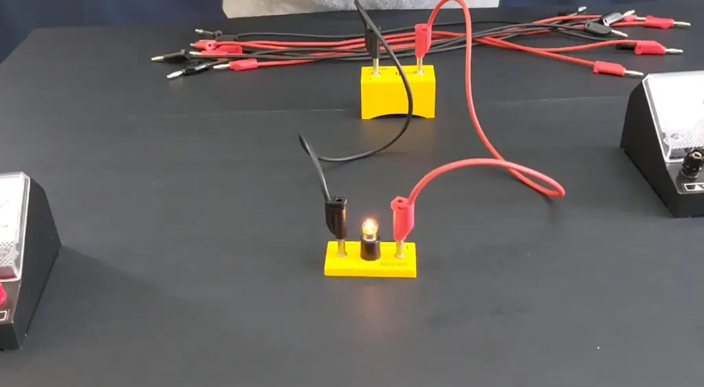
8. Is a voltmeter connected parallel to a bulb?
Yes, to measure the voltage across a bulb or any component in a circuit, a voltmeter is connected in parallel with the component.
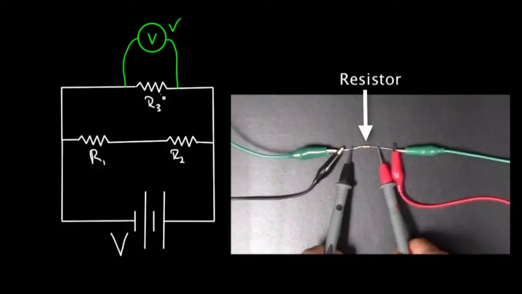
9. Is a voltmeter parallel to a resistor?
Yes, a voltmeter is connected in parallel with a resistor or any other circuit element to measure the voltage across it.
10. Does a voltmeter have resistance in parallel?
Yes, a voltmeter has high internal resistance in parallel, which ensures that it draws minimal current from the circuit it is measuring.
11. What happens to voltage in a parallel circuit?
In a parallel circuit, the voltage is the same across all components connected in parallel. This is a fundamental principle of parallel circuits.
12. Does voltage stay the same in parallel?
Yes, in a parallel circuit, the voltage remains the same across all components connected in parallel.
13. Are voltmeters always wired in parallel?
Yes, voltmeters are always wired in parallel when measuring voltage to avoid loading the circuit and obtain accurate readings.
14. Can I measure AC voltage with a voltmeter designed for DC measurements?
No, you cannot measure AC voltage accurately with a voltmeter designed for DC measurements. DC voltmeters are calibrated to measure the average voltage of a DC waveform, while AC voltage varies continuously between positive and negative peaks. To measure AC voltage, you need an AC voltmeter or a multimeter with an AC voltage setting.
15. Can I measure voltage without disconnecting the circuit component?
Yes, in most cases, you can measure voltage without disconnecting the circuit component. Since a voltmeter has a high internal resistance, it draws very little current, so it won’t significantly affect the circuit. However, if you need to measure the voltage across a sensitive component, it’s good practice to disconnect one end of the component to avoid potential interference.
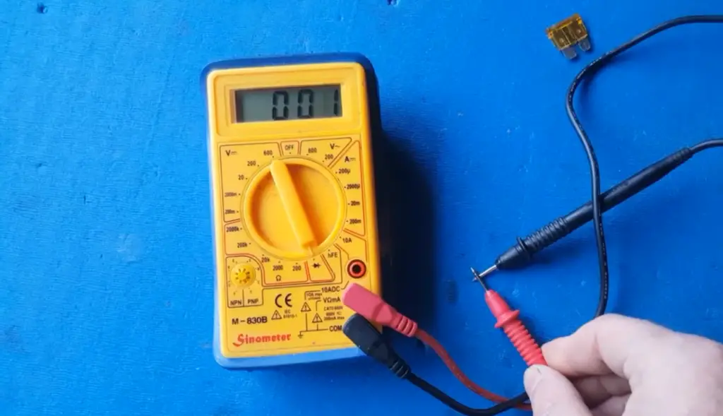
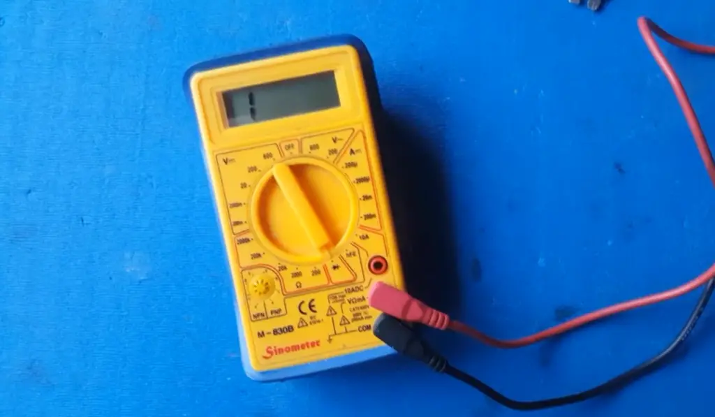
16. Can I use a digital multimeter as a voltmeter?
Yes, a digital multimeter (DMM) can function as a voltmeter by setting it to the appropriate voltage measurement mode. DMMs are versatile tools that can measure various electrical parameters, including voltage, current, resistance, and more.
17. What should I do if the voltmeter reads “Overload” or “OL”?
If the voltmeter displays “Overload” or “OL”, it means the measured voltage exceeds the maximum range of the voltmeter. To obtain a valid reading, switch to a higher voltage range on the voltmeter until you get a suitable measurement.
18. Can I leave the voltmeter connected to a circuit for an extended period?
Leaving the voltmeter connected to a circuit for an extended period is generally safe, as long as the circuit is not powered. However, it’s best to disconnect the voltmeter when not actively taking measurements to preserve battery life and avoid accidental voltage measurement errors.
19. Can I use a voltmeter to check the voltage of the batteries?
Yes, you can use a voltmeter to check the voltage of batteries. Ensure the voltmeter is set to an appropriate DC voltage range, and connect the probes to the battery terminals. For example, a fully charged 1.5V AA battery should read around 1.5V on the voltmeter.
20. How do I test the accuracy of my voltmeter?
To test the accuracy of your voltmeter, you can use a known stable voltage source (such as a calibrated power supply) and compare the voltmeter’s reading with the known voltage. If there are significant discrepancies, consider calibrating or adjusting the voltmeter if possible.
21. Can I measure voltage in high-voltage circuits with a regular voltmeter?
For high-voltage circuits, you need a voltmeter with a suitable voltage range that can handle the maximum voltage of the circuit safely. High-voltage measurements require specialized high-voltage voltmeters or voltage probes to ensure operator safety and accurate readings.
22. Can I use a voltmeter to measure the voltage drop across a component in a circuit?
Yes, you can use a voltmeter to measure the voltage drop across a component in a circuit. Connect the voltmeter in parallel across the component to obtain the voltage drop value.
23. What precautions should I take when measuring voltage in potentially hazardous circuits?
When measuring voltage in potentially hazardous circuits (such as high-voltage systems or live circuits), use appropriate personal protective equipment (PPE) like insulated gloves and safety goggles. Follow safety guidelines and work with extreme caution to prevent electrical shocks or injuries.
Useful Video: How to use multimeter to measure Voltage , Current and Resistance
References
- https://pressbooks.uiowa.edu/clonedbook/chapter/dc-voltmeters-and-ammeters
- https://www.toppr.com/ask/question/how-is-a-voltmeter-connected-in-the-circuit-to-measure/
- https://www.circuitsgallery.com/how-is-a-voltmeter-connected-in-a-circuit/
- https://byjus.com/question-answer/how-is-a-voltmeter-connected-in-the-circuit-to-measure-the-potential-difference-between-two-points/
- https://unacademy.com/content/jee/study-material/physics/voltmeter/
- https://toolsweek.com/how-is-a-voltmeter-connected-in-a-circuit/
- https://unacademy.com/content/question-answer/physics/why-voltmeter-is-connected-in-parallel/#:~:text=The%20voltmeter%20is%20connected%20in,full%20voltage%20and%20high%20resistance