
Ever been perplexed on how to figure out the voltage between two resistors connected in series? Look no further than the reliable Voltage Divider Rule! With a fundamental knowledge of algebra, you can apply this straightforward rule to calculate the voltage decay across two resistors in series. Ready to delve into the voltage divider rule? Then keep reading!
What is a Voltage Divider?
To regulate electrical current and voltage, a voltage divider utilizes two resistors or other types of passive components connected in series. By defining the ratio between voltage at each node, we can calculate with ease the output voltage of this divider. According to the Voltage Divider Rule (VDR), the output voltage of a divider is equivalent to the input voltage multiplied by the ratio of two resistors.
At its simplest, when two resistors are linked in series, the total power supply voltage is proportionally separated according to their individual resistance ratios. By using Ohm’s Law (V=IR), it is possible to determine how much current each component will draw and how much potential difference exists across them. By calculating the potential difference, we can measure and determine the output voltage of this divider – an essential step to any successful electrical circuit. [1]
What is the Voltage Divider Rule?
If you want to discover the voltage output of a circuit containing two resistors, this equation can help! According to the rule, in a series circuit, the resistor values’ ratio decides how much voltage is produced across each component. As an illustration, if you have a circuit with two resistors (R1 and R2) in which R1 possesses twice the resistance of R2, then there will be twice as much voltage lost by way of R1 than through its counterpart. To find the total voltage drop for both resistors, you simply use Ohm’s Law V = IR, where I is the current through both resistors and R is their combined resistance value. This can be expressed mathematically as:
Vout = Vin *(R2/(R1 + R2))
The voltage divider rule is useful in many applications because it allows engineers to accurately calculate the voltage drop across a wide range of components. For example, if an engineer is trying to design a circuit with two resistors that need to provide 12V, they can easily calculate the required resistor values by using the VDR equation. This makes it simple and efficient to design circuits with multiple components that require specific voltage drops.
Not only can the voltage divider rule be employed to calculate precise values when constructing circuits, but it is also useful for measuring resistance levels that are unknown. By connecting two known resistors in series and measuring the output voltage, you can use Ohm’s Law and the VDR equation to solve for R1 or R2. [2]
When to Use the Voltage Divider Rule?
Leverage the power of voltage divider rule to lower the amount of voltage applied in an electrical circuit. It is particularly useful when dealing with circuits that require different sets of voltages, as it can be used to adjust the voltage input so that each component receives the desired level.
It’s commonly used in radio-frequency (RF) applications such as amplifiers, antennas, and filters, as well as many other types of electronics projects.
It may also be necessary to use the voltage divider rule when working with multiple sources in a single circuit. By reducing the voltage applied to certain components, you can optimize how much power is going to each part. This could be necessary for example if one component requires less voltage than another, or if a particular set of components needs to share a single power source.
The voltage divider rule can also be used when building simple circuits with standard resistors and capacitors. In this scenario, it’s important to adjust the voltage so that the correct amount of current flows through each component – too little current and your circuit won’t work as efficiently as it should; too much current and it could cause damage. With an understanding of the basic principles behind the rule, you’ll be able to quickly adjust voltages in any electronic circuit. [3]
Voltage Divider Formula
It is a simple equation used in electronics to calculate the output voltage of a circuit. It is based on Ohm’s Law, which states that the current in a circuit is equal to the voltage divided by the resistance. Voltage division occurs when two resistors are connected in series with a voltage source, such as an AC or DC power supply.
The ratio between these two resistors determines what fraction of the input voltage will be able to pass through them and reach the output side of the circuit. This is known as “voltage division” and can be calculated using the formula Vout = (R1 / R1 + R2) * Vin, where Vout is the output voltage from the divider, Vin is the input voltage applied across both resistors, R1 is the resistance of the first resistor and R2 is the resistance of the second resistor.
The voltage divider rule can be used to design circuits with a specific output voltage or to measure an unknown source voltage by using two known resistances. It can also be used to create a power supply with adjustable output voltages and currents. Understanding this basic formula and its applications will help engineers design efficient circuits for their projects.
Voltage Divider Examples
The Voltage Divider Rule is an electrical engineering principle that can be used to calculate the voltage drop across a resistor in a simple series circuit. It states that the total voltage is divided among all of the resistors according to their relative values. This rule can be used to explain how voltage drops occur in circuits, and it can also be used to calculate voltages in practical applications.
Let’s take a look at some examples of how the Voltage Divider Rule works. Suppose we have a circuit with two resistors connected in series, each having resistance R1 and R2 respectively. The total resistance of this circuit would then be equal to R1 +R2. According to the Voltage Divider Rule, the voltage drop over each resistor is then proportional to the resistances:
V1 = (R1 / (R1 + R2)) * Vtotal
V2 = (R2 / (R1 + R2)) * Vtotal
In this example, V1 would represent the voltage drop across resistor R1 and V2 would be the voltage drop across resistor R2.
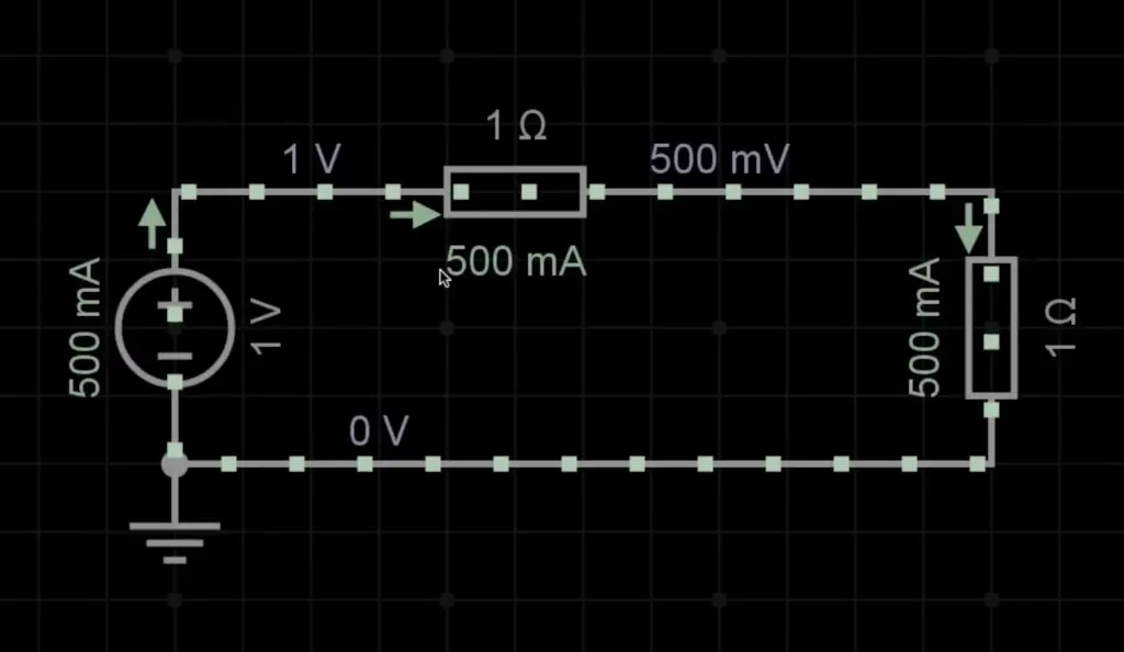
Let’s say that in our circuit, we have a total applied voltage of 10V and the two resistors are equal at 5 ohms each. We can then calculate how much voltage will be dropped over each resistor using the Voltage Divider Rule:
V1 = (5 / (5+5))*10V = 5V
V2 = (5 / (5+5))*10V = 5V
So, in this example, we can see that the voltage drop is equal across both resistors since they have the same resistance value.
We can also use the Voltage Divider Rule to calculate how much current is flowing through each resistor in our circuit. Since current is simply the rate of flow of charge, and since charge must be conserved throughout a series circuit, then the total current at any point in the circuit must remain constant. Therefore, if I1 is the current flowing through R1, and I2 is the current flowing through R2, then:
I1 = I2
and
I1 = Vtotal / R1+R2
Using our example above, we can now calculate the current flowing through each resistor:
I1 = 10V / (5+5) = 1A
I2= 10V / (5+5) = 1A
As you can see, in this circuit, the current is equal and constant throughout.
In conclusion, the Voltage Divider Rule is a useful tool for understanding voltage drops in series circuits and for calculating voltages and currents. It allows us to quickly determine how much voltage will be dropped across each resistor in any given circuit. With practice, it can help us design more efficient systems that utilize less power while still providing maximum performance. [4]
Capacitive Voltage Dividers
The voltage divider rule describes a simple circuit that connects two resistors in series, with the output voltage being taken across one of the resistors. The same rule applies to capacitive dividers, where two capacitors are connected in series and the output voltage is taken across one of them. In this case, since capacitors oppose changes in voltage, the output voltage will be less than the input voltage.
A basic example of a capacitor voltage divider would consist of two identical capacitors each with a value of 100 nanofarads (nF). When an input voltage is applied to this circuit, the output voltage will appear as Vout = Vin * C1/(C1+C2) = Vin * 0.5. This means that if the input voltage is 10 volts, the output voltage would be 5 volts.
Capacitive voltage dividers are commonly used in communication systems and oscillator circuits. In communication systems they can be used to reduce noise or control signal levels. In oscillators they can be used to control amplitude and frequency of the signals generated. They are also useful for impedance matching between stages in a circuit as well as for power supply decoupling purposes.
In conclusion, capacitive voltage divider circuits allow us to reduce an input voltage by a certain factor, making them very useful for many applications such as communication systems, oscillators, impedance matching and power supply decoupling. They offer advantages over resistive dividers due to their wide range of frequencies, low losses and high linearity. As a result, capacitive voltage dividers are essential components in modern electronics.
Inductive Voltage Dividers
This is done by connecting an inductor with a resistor in series and then measuring the voltages present at each connection point. The Voltage Divider Rule (VDR) states that the ratio of output voltages is equal to the ratio of resistance values connected in series. This simple rule can be used to calculate voltage drops across resistors, providing accurate solutions for complex circuits.
With this knowledge, engineers can design efficient powering solutions for any application, from automotive electronics to microchips. Additionally, IVDs are also used in the control systems of self-driving cars and other autonomous vehicles, where precise control over power distribution is needed for safety reasons. By using the Voltage Divider Rule, engineers can ensure that all components of the system receive the required voltage, with minimal power losses. [5]
Voltage Divider Example Problems
Voltage divider circuits can be used to solve a variety of problems. Consider the following example:
Suppose we have a 12-volt DC power supply and want to divide it into two 6-volt outputs. To do this, we need to use an IVD with two resistors – one with resistance R1, and another with resistance R2.
Using the Voltage Divider Rule, we can calculate that R1 must be twice as large as R2 in order for the voltage output to be equal.
In other words, if R1 = 8 Ohms and R2 = 4 Ohms, then the output voltages will both be 6 volts. This same principle can also be applied to AC voltage dividers, where the resistors must be connected in parallel with a capacitor, instead of series.
Ultimately, understanding and applying the Voltage Divider Rule is an essential skill for any electrical engineer or technician, as it can help them calculate accurate voltage drops across various components. By using this simple equation, engineers can design efficient powering solutions for any application – from automotive electronics to microchips. With this knowledge, they can further their careers and lead successful projects that have tremendous impact on the world around us.
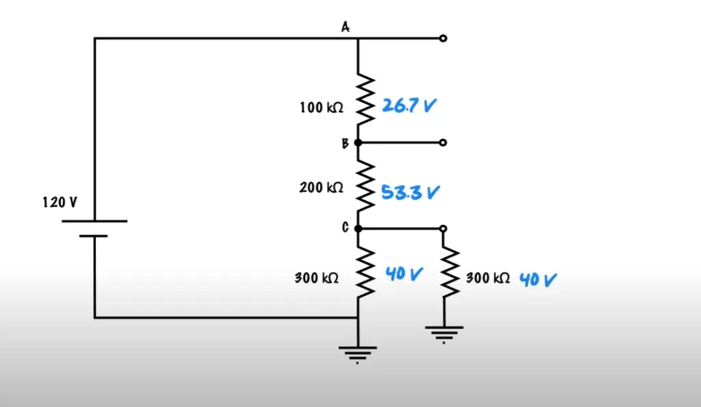
Voltage Tapping Points in a Divider Network
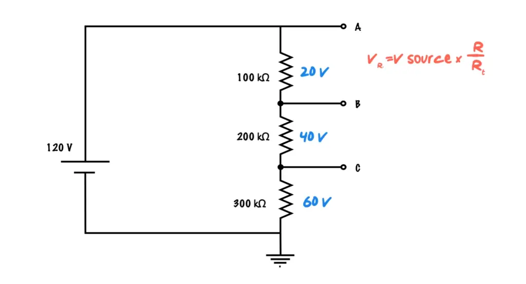
The voltage divider rule is an important electrical engineering principle that can be applied to a variety of circuits. It states that the voltage at any tapped point in a series-connected resistor network will be equal to the ratio of resistances between that particular node and ground multiplied by the supply voltage. This allows engineers to employ the divider rule to calculate expected voltages at each node in order to determine if they have designed their circuit correctly.
Additionally, it can help them troubleshoot when incorrect voltages are detected during testing. The use of this rule enables engineers to make quick calculations with minimal effort and provide accurate results. In addition, understanding how resistance values affect voltage tapped points provides valuable insight into designing efficient networks for various applications.
By understanding the fundamentals behind the voltage divider rule, engineers can make educated decisions when designing and troubleshooting electrical circuits. This will ensure that their devices operate as expected and be reliable for long-term use.
For example, let’s say you want to design a simple circuit with two resistors connected in series between a 5V power source and ground. If the first resistor has a resistance of 100 ohms and the second resistor is 200 ohms, then the voltage at any tapped point in this network will be 4V (5V * (100/300)). With this knowledge, an engineer can accurately determine what voltage levels to expect throughout their design without spending time on manual calculations or testing.
Applications of Voltage Divider Rule
The Voltage Divider Rule can be used for a number of applications, such as measuring voltage in electrical circuits and controlling the current through certain components. It can also be used to control the output of a circuit by making adjustments to resistors within it.
Additionally, this rule is often utilized in low-voltage power supplies, allowing engineers and designers to easily adjust their design’s parameters. Most importantly, the Voltage Divider Rule is essential when designing high-impedance analog circuits that are sensitive to input voltages. By leveraging this useful concept, engineers and designers have access to more precise control over the circuit than ever before.
The Voltage Divider Rule is a powerful tool that has been embraced by the modern engineering community due to its utility and simplicity. By understanding this concept, engineers and designers can take full advantage of the vast possibilities it provides in circuit design.
In conclusion, the Voltage Divider Rule is a fundamental tool that is widely used in engineering and design. It can be used for a variety of applications, including measuring voltage in electrical circuits, controlling current through components, adjusting resistors within a circuit to control its output, and designing high-impedance analog circuits with precise control over voltages. As such, this rule is an essential part of modern engineering projects. [6]
FAQ
What does the voltage divider rule state?
The voltage divider rule states that the voltage across a series circuit is equal to the sum of all individual voltages in the circuit, divided by the total resistance. In other words, it states that the total voltage across a series circuit can be calculated using Ohm’s Law and dividing it by the total resistance. This can be written mathematically as V = V1 + V2 + … + VR / R, where V is the total voltage across the circuit and R is the total resistance. This equation can then be used to calculate any unknown values for a particular circuit.
What are some applications of this rule?
The most common application of the voltage divider rule is in designing circuits with multiple resistors connected in series. By using Ohm’s Law and the voltage divider equation, it is possible to calculate the individual voltages across all of the resistors in the circuit. This rule can also be used to accurately measure potential differences between two points in a circuit, by connecting a known resistor between them and measuring the voltage across it. Additionally, this rule is useful for calculating currents in complex circuits with multiple resistors. Finally, this rule can be used to analyze transistor circuits and other non-linear components.
What are some limitations of this rule?
The voltage divider rule does not take into account any additional sources of resistance or impedance within a circuit, such as inductance or capacitance. Additionally, this equation does not take into account any changes in the resistance of a circuit due to temperature or other environmental factors. Finally, this equation does not include any effects due to parasitic elements such as resistors or capacitors that may be present in a circuit. In these cases, more complex methods of analysis must be used to accurately calculate potential differences and currents throughout the circuit.
Is there anything else I should know about this rule?
Generally speaking, it is important to remember that the voltage divider equation only applies when all components in the series are at the same temperature and have constant resistance throughout their operating range. If any of these conditions are not met, then more advanced techniques must be used in order to accurately calculate voltages and currents within a given circuit. Additionally, it is important to note that this equation does not account for any changes in resistance due to non-linear components or environmental factors. Finally, it is important to be aware of the potential hazards associated with working with high voltages and currents – always take proper safety.
Useful Video: What is Voltage Divider And Current Divider Rule | VDR and CDR With Practical Experiment
Conclusion
The Voltage Divider Rule is a powerful tool for understanding the behavior of electrical circuits. By using this rule, one can quickly calculate the voltage across any resistor in a circuit without having to solve any complex equations. This can be particularly useful when analyzing circuits with multiple resistors and determining how each component affects the overall performance of the system. With its consistent application, it helps simplify many problems and provides a reliable method for calculating voltages and currents within a circuit.
Overall, the Voltage Divider Rule proves to be an invaluable resource that opens up many possibilities in terms of understanding electricity and electrical components. It enables engineers to analyze circuits efficiently and accurately so they can better understand how their systems work—and how best to optimize them for maximum performance. With the Voltage Divider Rule, there are far fewer unknowns to contend with and more confidence in the reliability of the results.
Therefore, for anyone working with or studying electricity, it is worthwhile to become familiar with this simple yet powerful rule. Understanding how it works can provide a valuable foundation that will prove immensely useful in any electrical project or research endeavor.
References
- https://study.com/learn/lesson/voltage-divider-circuit-rule-bias-formula.html
- https://www.elprocus.com/voltage-divider-rule-with-examples/
- https://www.seeedstudio.com/blog/2019/10/09/voltage-dividers-everything-you-need-to-know/
- https://www.electronics-tutorials.ws/dccircuits/voltage-divider.html
- https://www.electricalclassroom.com/voltage-division-rule-potential-divider-circuit/
- https://electricalbaba.com/voltage-division-rule-explanation-formula-derivation/