

When working with electronic components, understanding their properties and characteristics is essential. One common component encountered in circuits is the resistor, which is designed to regulate the flow of electric current. A question that often arises is whether resistors have polarity.
In this article, we will delve into the concept of resistor polarity and provide a comprehensive explanation. We will explore the general nature of resistors, discuss the absence of polarity in most resistors, examine specific cases where polarity may be relevant, and provide practical insights into working with resistors in electronic circuits.
By the end, you will have a clear understanding of the role of polarity, or lack thereof, in resistors.
What Is Polarity?
Polarity refers to the separation of charges within a molecule, resulting in the creation of positive and negative regions [1]. It is a fundamental concept in chemistry and is crucial in understanding various aspects of molecular behavior and interactions. Polarity is determined by the electronegativity difference between atoms within a molecule.
In a covalent bond, electrons are shared between atoms. However, not all atoms share electrons equally. Electronegativity is the ability of an atom to attract electrons towards itself. When two atoms with different electronegativities form a bond, the more electronegative atom pulls the shared electrons closer to itself, resulting in an uneven distribution of charge. This creates a polar bond, with one end being more negative and the other more positive.
To determine the overall polarity of a molecule, one must consider the individual polarities of its bonds and their molecular geometry. If a molecule has polar bonds, but they are symmetrically arranged, the individual bond polarities may cancel each other out, resulting in a nonpolar molecule. However, if the bonds are asymmetrically arranged, the molecule is typically polar.
Water (H2O) is a classic example of a polar molecule. The oxygen atom is highly electronegative compared to hydrogen, causing the electrons to be pulled closer to the oxygen.
As a result, the oxygen end of the molecule has a partial negative charge (δ-) while the hydrogen ends have partial positive charges (δ+).
This polarity gives rise to various unique properties of water, such as its ability to form hydrogen bonds and its high surface tension.
Polarity plays a vital role in many chemical processes. Solubility, for instance, is influenced by the polarity of both solute and solvent. Polar substances tend to dissolve in polar solvents, while nonpolar substances dissolve better in nonpolar solvents. This principle explains why oil and water do not mix—the polar water molecules are not attracted to nonpolar oil molecules.
Do Resistors Have Polarity?
Polarity refers to the presence of positive and negative terminals or a specific orientation in an electronic component. It determines the direction in which current can flow through the component. However, resistors are symmetrical components that do not have a fixed orientation or distinct terminals.
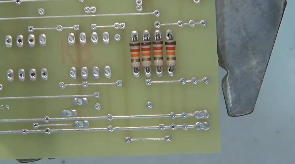
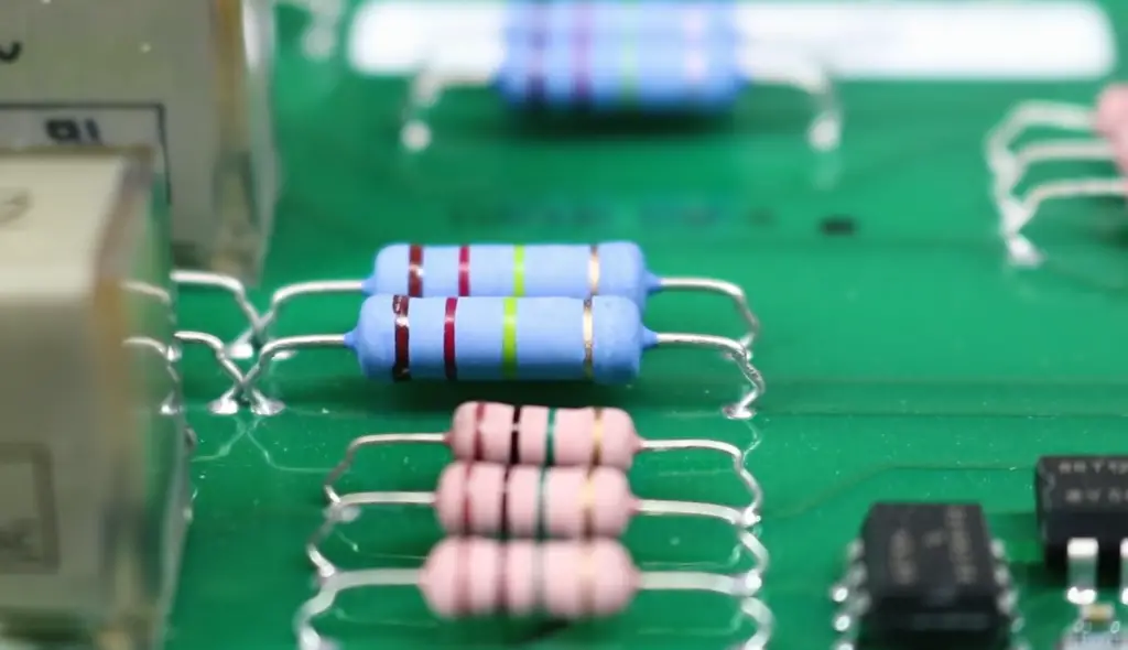
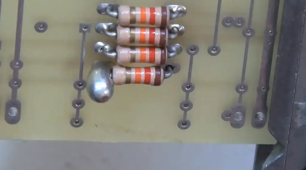
Resistors are constructed using materials with high resistance, such as carbon composition, metal film, or wire-wound materials. These materials are typically cylindrical or rectangular in shape and have two leads or terminals that allow them to be connected within a circuit. However, the orientation or position of these leads does not affect the functionality or behavior of the resistor.
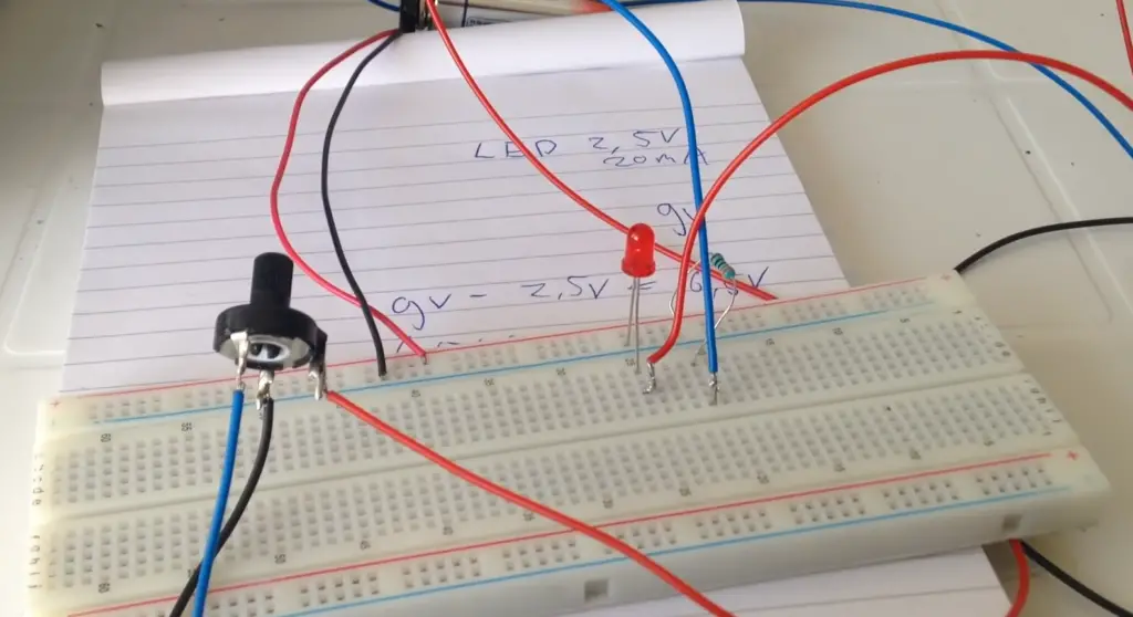
When connecting a resistor in a circuit, it can be inserted in either direction without any impact on its performance. The flow of current through a resistor is determined by the voltage difference across it and the resistance value, rather than any specific polarity.
The voltage drop across a resistor is proportional to the current flowing through it and its resistance, as described by Ohm’s Law (V = I * R) [2].
It is worth noting that resistors are passive components, which means they do not generate or amplify electrical signals. Their purpose is to impede or limit the flow of current in a circuit.
They dissipate electrical energy in the form of heat as the current passes through them, according to Joule’s Law (P = I^2 * R). This heat dissipation is independent of any polarity considerations.
In electronic circuit diagrams or schematics, resistors are often represented by simple symbols consisting of a rectangle with two leads. These symbols do not indicate any specific polarity but serve as a visual representation of the resistor’s function within the circuit.
What Are The Specs Of The Resistors With Polarity?
Resistors are passive electronic components that regulate the flow of electric current in a circuit. They are typically designed to be non-polarized, meaning they do not have specific polarity or orientation.
However, some specialized resistors have polarity due to their unique construction or function. Here are a few examples:
- Light-dependent resistors (LDRs): LDRs, also known as photoresistors, are resistors whose resistance changes with varying light levels. They have a photosensitive surface that exhibits different resistance values depending on the intensity of incident light. LDRs are non-polarized in terms of electrical polarity but require proper illumination for their operation;
- Varistors: Varistors are voltage-dependent resistors used for transient voltage suppression. They have a nonlinear resistance characteristic, which means their resistance decreases as the voltage across them increases. Varistors are commonly used to protect electronic circuits from voltage spikes or surges. While varistors may have polarity markings to indicate their orientation within a circuit, their electrical behavior does not depend on polarity;
- Thermistors: Thermistors are resistors whose resistance changes with temperature. They are often used for temperature sensing and compensation in various applications. There are two types of thermistors: positive temperature coefficient (PTC) and negative temperature coefficient (NTC). PTC thermistors have an increasing resistance with temperature, while NTC thermistors have a decreasing resistance with temperature. Thermistors typically do not have electrical polarity but may be labeled to indicate the temperature coefficient and identification of their leads;
It is important to note that these specialized resistors with polarity markings or orientation considerations are exceptions rather than the norm. The majority of resistors used in electronic circuits, such as carbon composition, metal film, or wire-wound resistors, are non-polarized and can be connected in any direction within a circuit without regard to polarity.
What Are Non-Polarized Capacitors?
Non-polarized capacitors, also known as non-polar capacitors, are types of capacitors that do not have a specific polarity or orientation. Unlike polarized capacitors, such as electrolytic capacitors or tantalum capacitors, which have distinct positive and negative terminals, non-polarized capacitors can be connected in any direction within a circuit without regard to polarity.
Non-polarized capacitors are commonly used in circuits where the applied voltage can reverse or alternate its polarity. They are typically made using materials like ceramic, film, or paper, which have symmetrical properties and do not exhibit a specific polarity.
There are two main types of non-polarized capacitors:
- Ceramic Capacitors: Ceramic capacitors are among the most common types of non-polarized capacitors. They are constructed using ceramic materials as the dielectric, which provides insulation between the capacitor’s plates. Ceramic capacitors come in various shapes and sizes and offer a wide range of capacitance values. They are suitable for applications that require small capacitance values and high-frequency response;
- Film Capacitors: Film capacitors are another type of non-polarized capacitors. They are made by sandwiching a thin plastic or polymer film between two metal foil electrodes. The plastic film acts as the dielectric, providing insulation and determining the capacitance value. Film capacitors have good stability, high voltage ratings, and low leakage currents, making them suitable for a wide range of applications [3];
Non-polarized capacitors are often used in coupling, decoupling, timing, and filtering applications in electronic circuits. They can be employed in AC (alternating current) circuits or circuits where the voltage can reverse its polarity. Since non-polarized capacitors do not have polarity constraints, they offer flexibility in circuit design and ease of installation.
It is important to note that the capacitance value, voltage rating, and other specifications of non-polarized capacitors should be carefully considered when selecting them for a specific circuit application. The manufacturer’s datasheet or specifications provide detailed information about these parameters and help ensure the capacitor’s suitability for the intended use.
What Is An Integrated Circuit (IC)?
These components are interconnected through a network of conducting pathways, typically made of metal, etched onto the chip’s surface.
Integrated circuits revolutionized the field of electronics by enabling the miniaturization and increased functionality of electronic systems. They are used in a wide range of applications, including computers, smartphones, televisions, automobiles, medical devices, and many more.
The development of integrated circuits can be attributed to the work of engineers Jack Kilby and Robert Noyce in the late 1950s and early 1960s. Kilby, at Texas Instruments, and Noyce, at Fairchild Semiconductor and later Intel, independently pioneered the concept of integrating multiple electronic components onto a single piece of semiconductor material.
Integrated circuits are classified into two main categories based on their construction and complexity:
- Small-Scale Integration (SSI): SSI refers to integrated circuits that contain a relatively small number of transistors and other components. These circuits typically have simple functions and are used in basic logic gates, amplifiers, and other simple electronic circuits;
- Large-Scale Integration (LSI): LSI refers to integrated circuits that contain a large number of transistors and other components, typically numbering in the thousands or millions. These circuits are highly complex and can perform a wide range of functions. LSI chips are commonly used in microprocessors, memory chips, and advanced digital systems;
Integrated circuits offer numerous advantages over traditional discrete electronic components. These advantages include:
- Miniaturization: By integrating multiple components onto a single chip, ICs allow for the miniaturization of electronic systems. This enables the development of smaller, lighter, and more portable devices;
- Improved Performance: The close proximity of components on an integrated circuit reduces the distance that signals need to travel, resulting in faster operation and improved performance;
- Reliability: Integrated circuits are less susceptible to failures caused by loose connections or component damage, as the components are securely integrated onto the chip;
- Cost-Effectiveness: Mass production of integrated circuits has led to significant cost reductions, making them more affordable and accessible for various applications;
Integrated circuits have played a crucial role in advancing technology and shaping the modern world. They continue to evolve with advancements in semiconductor manufacturing processes, allowing for even greater levels of integration, increased functionality, and improved performance in electronic devices and systems.
Testing The Continuity Of A Resistor Using A Multimeter
Testing the continuity of a resistor using a multimeter is a simple process that can help determine if the resistor is functioning properly.
Here’s a step-by-step guide on how to test the continuity of a resistor using a multimeter:
- Set the Multimeter: Turn on the multimeter and set it to the continuity or resistance (ohms) mode. The exact setting may vary depending on the model of your multimeter, so consult the user manual if needed;
- Disconnect Power: Ensure that the circuit or device containing the resistor is disconnected from any power source. This is important to prevent any potential damage to the multimeter or the circuit;
- Connect the Test Leads: Insert the test leads into the appropriate sockets on the multimeter. The black test lead usually goes into the COM (common) socket, while the red test lead goes into the socket labeled for resistance or continuity testing;
- Zero the Multimeter (Optional): If your multimeter has a zero or auto-zero function, press the button to calibrate it to eliminate any resistance introduced by the test leads. This step may vary depending on your multimeter model, so refer to the user manual if needed;
- Touch the Test Leads: Touch the metal tips of the test leads together. This completes a circuit with known continuity and helps ensure the accuracy of the test. The multimeter should indicate continuity, typically with an audible beep or a visual display;
- Test the Resistor: Place the test leads across the resistor being tested. It doesn’t matter which lead goes on which end of the resistor since resistors are non-polarized. Ensure that the test leads make good contact with the resistor’s terminals or leads;
- Read the Multimeter: Observe the multimeter’s display or listen for the continuity beep. If the multimeter indicates continuity or a low resistance value (close to zero), it means the resistor is functioning properly. If there is no continuity or a high resistance value, it suggests that the resistor may be faulty or damaged;
- Interpret the Results: The actual resistance value of the resistor cannot be determined with a simple continuity test. The test only indicates if the resistor has a low resistance value, indicating continuity, or a high resistance value, indicating a break in the circuit;
- Disconnect and Power Off: Once the test is complete, disconnect the test leads from the resistor and turn off the multimeter [4];

FAQ:
1. Do resistors have continuity?
Resistors themselves do not exhibit continuity. They are designed to provide resistance to the flow of electric current. When testing a resistor for continuity using a multimeter, it is expected to show high resistance or no continuity.
2. Why do resistors have no polarity?
Resistors have no polarity because they are symmetrical components. Their resistance to current flow is independent of the direction in which they are connected in a circuit. They can be inserted in either direction without affecting their functionality.
3. Do resistors have a positive and negative side?
No, resistors do not have a positive or negative side. They are non-polarized components, meaning they can be connected in any direction within a circuit without any impact on their operation.
4. How do you determine the polarity of a resistor?
Resistors do not have polarity, so there is no need to determine their polarity. They can be connected in either direction without any effect on their functionality [5].
5. Is a 10-ohm resistor positive or negative?
A 10-ohm resistor does not have a positive or negative designation. It is a non-polarized component and can be connected in either direction within a circuit.
6. Does it matter if a resistor is backwards?
In most cases, it does not matter if a resistor is connected backward or in reverse. Resistors are not polarized, so they can function in either direction. However, there may be exceptions with certain specialized resistors that have specific polarity requirements.
7. Are some resistors polarity-sensitive?
While the majority of resistors are non-polarized, there are some specialized resistors that can be polarity-sensitive. For example, light-dependent resistors (LDRs) or some temperature-sensitive resistors (thermistors) may have specific polarity requirements due to their unique construction and behavior.
8. Are all resistors non-polarized?
No, not all resistors are non-polarized. While the most commonly used resistors, such as carbon composition, metal film, or wire-wound resistors, are non-polarized, there are exceptions with specialized resistors that may have specific polarity considerations.
9. Do switches have polarity?
Switches can have polarity in certain cases, depending on their design. Some switches, such as diode-based or polarized switches, may have specific polarity requirements. However, the majority of mechanical switches used in basic electronic circuits are non-polarized.
10. What happens if polarity is wrong?
If the polarity of a component is reversed or connected incorrectly, it may result in the malfunctioning or failure of the circuit or the component itself. Incorrect polarity can cause improper current flow, damage to sensitive components, or even short circuits.
11. Does polarity affect resistance?
No, polarity does not affect resistance. Resistance is a property of the material or design of the resistor and is independent of its polarity [6]. The resistance value remains the same regardless of the direction in which the resistor is connected.
12. Can resistors go in any direction?
Yes, resistors can be connected in any direction within a circuit. They are non-polarized components, and their functionality is not affected by their orientation.
13. Do resistors need to be exact?
The exactness of resistors depends on the specific application and requirements of the circuit. In some cases, precision resistors with tight tolerance values are necessary for precise voltage or current control. However, in many applications, standard resistors with moderate tolerances are sufficient.
14. Can a resistor be less than 1 ohm?
Yes, resistors can have resistance values less than 1 ohm. Resistors come in a wide range of values, including fractions of an ohm, milliohms (mΩ), or microohms (µΩ), depending on the specific application.
15. Can a resistor have 0 voltage?
Resistors themselves do not generate voltage. When a voltage is applied across a resistor, it experiences a voltage drop proportional to the current flowing through it according to Ohm’s law (V = IR). However, the voltage across a resistor can be very close to zero if the current through it is negligible or the resistance is very high.
Useful Video: How to Test a Resistor
References
- https://soldered.com/learn/what-is-polarity/
- https://www.axcontrol.com/blog/2021/do-resistors-have-polarity-mini-blog-post/13/10/
- https://electrotopic.com/does-a-resistor-have-polarity-why-or-why-not/
- https://electronicguidebook.com/do-resistors-have-polarity-and-continuity/
- https://electrical-information.com/resistor-polarity/
- https://www.physicsforums.com/threads/why-do-resistors-have-polarity.860104/