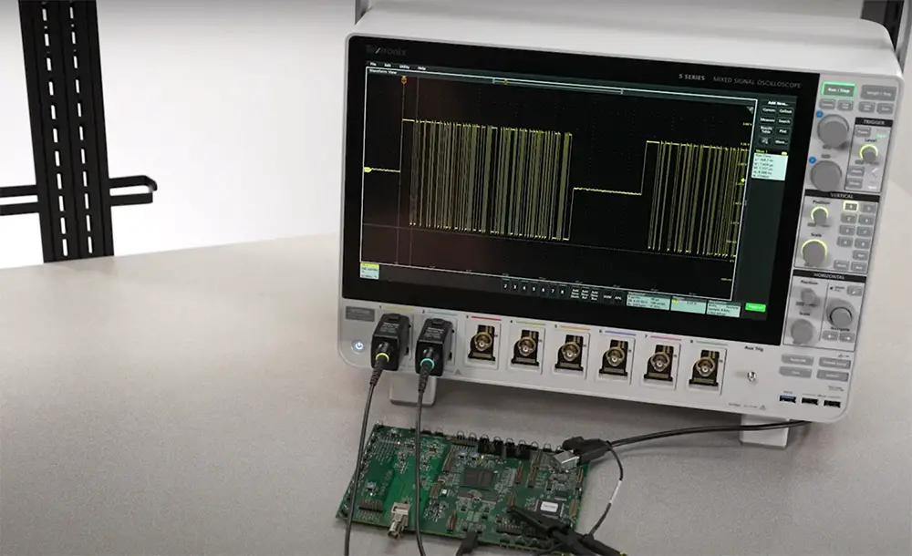
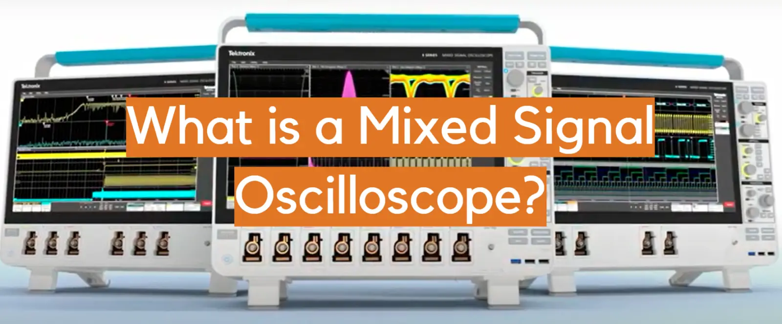
A mixed-signal oscilloscope, or MSO, is a type of oscilloscope that can measure and display both digital and analog signals. This type of oscilloscope is perfect for measuring and debugging electronic systems that contain both digital and analog components.
MSOs typically have four input channels, two of which are dedicated to analog signals and two of which are reserved for digital signals. Most MSOs also come equipped with a built-in logic analyzer, which makes them ideal for debugging digital systems [1].
An MSO can be perfect for anyone who is working with mixed-signal electronics because it can save you a lot of time when debugging your system.
In this blog post, we will discuss the basics of MSOs and how they can be used to troubleshoot electronics systems.
The Mixed Signal Oscilloscope/MSO Definition
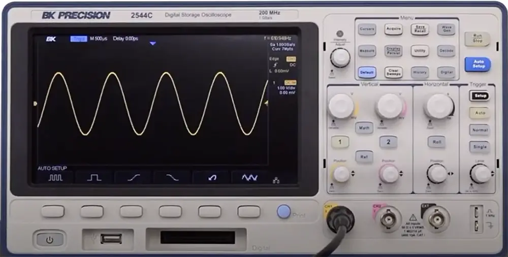
An MSO, or mixed-signal oscilloscope, is a piece of test equipment that combines the analog measurement channels of an oscilloscope with the logic channels of a logic analyzer. As the demand for combining analog and logical measurement channels on one device grows, so does the popularity of MSOs [2].
The term “mixed signal” generally refers to any system or device that uses both digital and analog signals. In an MSO, the addition of digital channels allows for the acquisition and display of time-correlated analog and digital data on a single screen. This correlation is vital when trying to debug mixed-signal designs.
Analog channels measure voltage levels while logic channels measure the state of digital signals (usually represented as high or low voltage levels). Most MSOs have between two and four analog input channels and 16 or more logic input channels. The number of available logic input channels is especially important because it determines how many buses can be monitored simultaneously.
When analyzing boards with logic components such as embedded systems using a microcontroller or MPU, it’s sometimes necessary to combine the analog channels of a traditional scope in order to examine waveforms while still seeing the logic levels on other parts of the circuit. Combining all of these elements together makes studying these systems much easier.
Why Use Mixed Signal Oscilloscopes?
It’s possible to examine these embedded systems using an MSO, which provides much more detail into their operation. A 2- or 4-channel scope combined with a 16-channel logic analyzer function would not be feasible, but it is conceivable to have a two- or four-channel scope linked with a 16-channel logic analyzer capability [3].
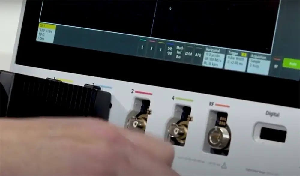
This is where MSOs come in. A mixed-signal oscilloscope has the ability to take measurements of both analog and digital signals, providing you with a comprehensive view of your circuit’s behavior. By combining the best features of both an oscilloscope and a logic analyzer, MSOs give you the power to debug and troubleshoot your circuits with ease.
If you’re working with embedded systems, then an MSO is a valuable tool that can save you time and hassle when trying to find problems. If you don’t need the extra channels, then a traditional scope will suffice; but if you find yourself needing more visibility into your circuit’s behavior, then an MSO is definitely worth considering.
MSO Capabilities
Most digital oscilloscopes have at least two channels, and many have four or more. Mixed-signal oscilloscopes (MSOs) take this a step further by adding one or more analog channels to the mix. This gives you the ability to not only see what’s happening on your digital lines but also correlate it with activity on your analog lines.
The MSO handles the oscilloscope and logic channels differently [4]:
1) Oscilloscope channels. These are true analog signals, which use an ADC to convert the analog inputs into a digital format. The waveform is then modified so that the analog features of the signal can be seen. This is useful for viewing digital and analog signals at the same time, as well as for quickly identifying any problems with your digital lines. Digital oscilloscopes usually have a bandwidth of around 20MHz, while MSOs can go up to 100MHz or more. This means that they can be used to view high-speed digital signals, as well as slower analog signals;
2) Logic channels. The mixed-signal oscilloscope’s logic channels are directly converted to a digital format. The screen displays the signals as a high or low level, and no analog information is shown. There are many more of these logic channels to allow for a comprehensive insight into the logic on a circuit, but because they don’t require complete analog to digital conversion, they are much simpler to implement. If you want to view the analog elements of a digital signal, connect it to one of the analog connections;
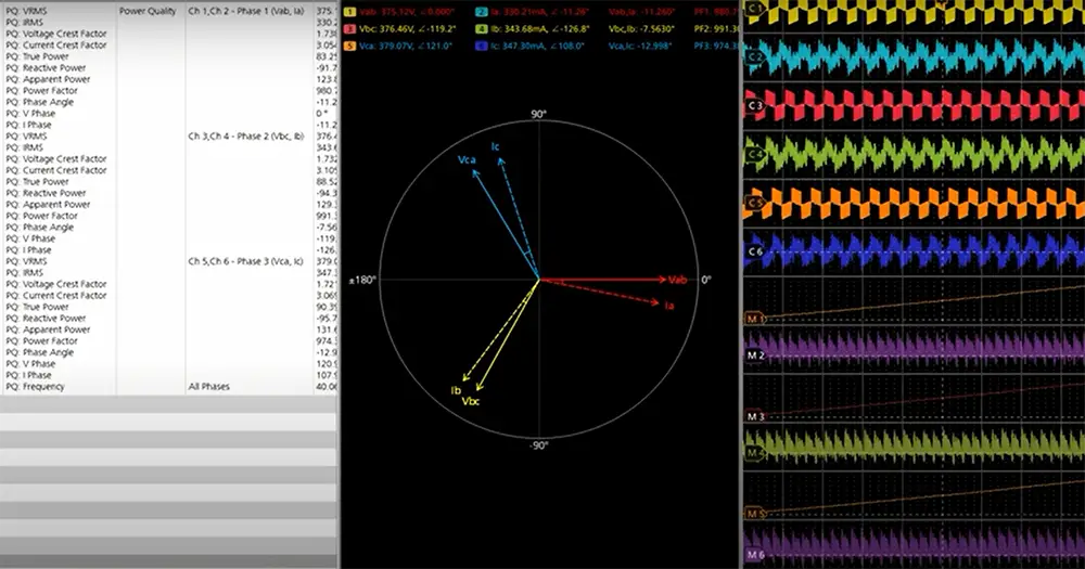
This is incredibly useful when you’re trying to debug mixed-signal designs, as you can quickly and easily see what’s going on with both your digital and analog signals at the same time. MSOs usually have all of the features and capabilities of a high-end digital oscilloscope, including deep memory, advanced triggering, and fast sample rates.
Comparison of Logic Analyzer and MSO
Oscilloscopes are the most accurate instruments for detecting and analyzing analog electronic signals, as well as assessing signal integrity and analog circuit performance. Logic analyzers are the most effective instruments for examining and monitoring digital electronic communications such as I2C, SPI, and Serial [15].
The key differences:
- Oscilloscopes are used to observe the behavior of an electrical signal over time, while logic analyzers are used to test digital circuits and systems by observing the logic states or voltages present at various points in the circuit;
- Oscilloscopes can measure both AC and DC signals, while logic analyzers can only measure digital signals;
- Oscilloscopes typically have two channels, while logic analyzers usually have eight or more;
- Oscilloscopes are generally more expensive than logic analyzers;
MSO Format
Oscilloscopes can be purchased in a variety of forms. The usual bench-top box design is popular, and many scopes use this style<. Many oscilloscope manufacturers expand their ranges by adding mixed-signal capabilities to certain instruments within their ranges.
USB PC-based mixed-signal oscilloscopes are also available, in addition to benchtop versions. These feature a maximum of 16 logic channels and may be expanded to two or four analog channels, giving them a highly powerful instrument [6].
What’s The Difference Between A Mixed-Signal Oscilloscope And A Logic Analyzer:
1) Which Instrument Is Home Base
Mixed-signal oscilloscopes (MSOs) are often thought of as the home base for digital measurements. MSOs offer more than just digital timing measurements; they also include analog channels to measure voltage. This is important when you’re debugging a system because you can see both digital and analog activity on the same time base. Oscilloscopes are ideal when your goal is to understand how a signal changes over time.
Logic analyzers are better suited for analyzing digital signals that occur at specific times, or events. A logic analyzer lets you trigger off of specific patterns in the data so you can view interesting sections of a long acquisition. Logic analyzers have a limited number of channels, but each channel can be multiplexed to observe many signals. This is useful when you want to know what a group of signals are doing at a specific moment in time.
2) State And Timing Analysis
Both MSOs and logic analyzers have fundamental architecture differences in how they acquire and show signals. An MSO exclusively utilizes asynchronous sampling, like an oscilloscope. Because it feels like a scope, for many individuals this makes getting started with an acquisition on digital channels simpler. There’s no need to understand the difference between timing and state analysis or to provide a clock signal. When running repeatedly in MSO systems, users get timely updates.
Logic analyzers, on the other hand, feature a wider range of acquisition modes, including both timing and state analysis. State analysis is an excellent method to collect information on buses with clocks that run in sync. The state captures only take place on valid clock conditions, which eliminates the capture of unimportant transition activity between valid clock signals. They also narrow down the captured time window by only utilizing logic analyzer memory when genuine states occur. Logic analyzers are optimized for detecting and displaying single-shot occurrences, but they have long gaps of dead time between acquisitions while operating repeatedly.
3) Triggering
Another big difference between MSOs and logic analyzers is in the triggering. Oscilloscopes feature a large variety of trigger types to select from, including edge, width, pulse, video, pattern, and serial triggers. With all these choices, you can set up an oscilloscope trigger to detect just about any kind of signal behavior.
Logic analyzers have a more limited selection of triggers because they are designed for digital signals. The most common type of logic analyzer trigger is the state trigger. State triggers let you specify a certain pattern of digital states (high or low) that must occur before the logic analyzer will start acquiring data. This lets you focus on specific events while ignoring other digital activities that might be going on.
Some logic analyzers also have edge triggers, which let you trigger a digital signal that makes a transition from one state to another (high-to-low or low-to-high). Edge triggers are less common on logic analyzers than state triggers because they are less specific. With an edge trigger, you might end up capturing a lot of data that is not relevant to what you are trying to troubleshoot [7].
There are a few things to keep in mind when choosing an MSO for your needs:
- First, make sure that the scope has enough channels to cover all of the signals in your design;
- Second, be sure to check the bandwidth and sample rate specs to ensure that the scope can handle the high-speed digital signals in your design;
- Finally, look at the feature set and make sure that the scope has all of the features and capabilities that you need;
Comparison of Mixed Signal Oscilloscopes
A Mixed Signal Oscilloscope (MSO) is a versatile electronic test instrument used to analyze both analog and digital signals. It combines the features of a traditional oscilloscope and a logic analyzer, making it ideal for debugging and analyzing complex electronic systems. Here, we present a comparison of key indicators for various Mixed Signal Oscilloscopes.
| Indicator | Definition | Importance |
|---|---|---|
| Number of Analog Channels | The count of input channels for analog signal measurement. | More channels offer simultaneous monitoring of multiple analog signals, useful for multi-channel systems. |
| Number of Digital Channels | The count of input channels for digital signal capture. | More channels allow capturing numerous digital signals concurrently, aiding in complex digital system analysis. |
| Bandwidth | The range of frequencies the oscilloscope can accurately measure. | Higher bandwidth ensures precise signal representation, especially for high-frequency applications. |
| Sample Rate | The rate at which the oscilloscope captures data points. | Higher sample rates provide more detailed signal visualization, crucial for capturing fast transients. |
| Memory Depth | The amount of data points the oscilloscope can store for analysis. | Greater memory depth allows capturing and analyzing longer-duration signals without loss of information. |
| Analog Resolution | The smallest voltage difference the oscilloscope can distinguish. | Higher resolution provides better accuracy when measuring small signal variations. |
| Record Length | The duration of time the oscilloscope can capture at the highest sample rate. | Longer record lengths are essential for observing rare or intermittent events over extended periods. |
| Trigger Types | The different signal conditions that can trigger data capture. | Various trigger options help isolate specific events or patterns in complex signals for in-depth analysis. |
| Display | The type and size of the oscilloscope’s screen. | A clear, large display enhances user experience and allows better observation of signals. |
| Connectivity Options | The available ports for connecting the oscilloscope to external devices. | Diverse connectivity options enable easy data transfer and remote control. |
The presented table offers a comparison of key indicators for Mixed Signal Oscilloscopes. These indicators include:
- Number of Analog Channels: The more channels an oscilloscope has, the more analog signals it can simultaneously measure, which is advantageous for monitoring complex systems.
- Number of Digital Channels: A higher count of digital channels allows the oscilloscope to capture multiple digital signals simultaneously, making it suitable for analyzing intricate digital systems.
- Bandwidth: A higher bandwidth ensures that the oscilloscope can accurately represent signals with higher frequencies.
- Sample Rate: A higher sample rate enables the oscilloscope to capture and display fast-changing signals more accurately.
- Memory Depth: A greater memory depth allows the oscilloscope to store more data for analysis, particularly useful for long-duration signal capture.
- Analog Resolution: A higher analog resolution results in better measurement accuracy for small signal variations.
- Record Length: Longer record lengths allow capturing rare or intermittent events over extended time periods.
- Trigger Types: Various trigger options help isolate specific events or patterns in complex signals for detailed analysis.
- Display: A clear and large display enhances user experience and allows better observation of signals.
- Connectivity Options: Diverse connectivity options facilitate data transfer and remote control of the oscilloscope.
By considering these indicators, users can make informed decisions when choosing a Mixed Signal Oscilloscope that suits their specific measurement requirements and applications.
FAQ
What is a mixed-signal oscilloscope used for?
A mixed-signal oscilloscope (MSO) is a type of electronic test instrument that allows you to measure both digital and analog signals on the same screen. This can be extremely helpful when trying to debug or troubleshoot circuits, as you can see how the different signals are interacting with each other.
What are the different types of oscilloscopes?
There are three main types of an oscilloscope:
- Analog oscilloscopes are the most basic type and measure the voltage over time;
- Digital oscilloscopes convert the voltage into a digital signal that can be displayed on a screen;
- Mixed-signal oscilloscopes, as the name suggests, can measure both digital and analog signals;
What is a digital sampling oscilloscope?
A digital sampling oscilloscope is a type of digital oscilloscope that uses a technique called “sampling” to measure the voltage of a signal. Sampling involves taking snapshots of the signal at regular intervals and then reconstructing the signal from these samples. This allows for very accurate measurements, but can also be quite slow depending on the speed of the ADC (analog-to-digital converter) [8].
What is a dual-beam oscilloscope?
A dual-beam oscilloscope is a type of oscilloscope that has two electron beams instead of just one. This allows for more accurate measurements, as the two beams can be used to cancel out each other’s errors [9].
How do you read Lissajous figures?
The X-Y plot’s shape indicates the phase difference in the Lissajous pattern. A straight line indicates a 0° or 180° phase difference. The angle of the line is determined by the difference in amplitude between the two signals; a line at 45° to the horizontal indicates that the amplitudes are equal [10].
Can an oscilloscope measure DC voltage?
Yes, an oscilloscope can measure DC voltage. However, most oscilloscopes are designed for AC signals, so you may need a special adapter in order to measure DC voltages.
Is an oscilloscope a voltmeter?
A voltmeter is a device that measures the difference in voltage between two points. If the oscilloscope is a Cathode Ray Oscilloscope (CRO), it may be used as a voltmeter. This technique can be utilized to measure potential differences between the two locations [11].
What is the difference between a mixed-signal oscilloscope and a digital oscilloscope?
Analog oscilloscopes can only display analog signals, while digital oscilloscopes can capture and analyze digital signals. However, a mixed-signal oscilloscope combines the capabilities of both, enabling the observation of both analog and digital signals simultaneously.
How does a mixed-signal oscilloscope handle digital signals?
A mixed-signal oscilloscope uses digital channels to capture and display digital signals. These channels can represent binary data, making it easier to analyze the digital characteristics of a system along with the analog waveforms.
What are the advantages of using a mixed-signal oscilloscope over separate instruments?
One significant advantage is the ability to correlate analog and digital signals in real-time. This correlation helps in debugging complex systems where analog and digital signals interact. Additionally, it saves bench space and reduces costs compared to having separate oscilloscopes for analog and digital signals.
Can a mixed-signal oscilloscope handle high-speed digital signals?
Yes, modern mixed-signal oscilloscopes are designed to handle high-speed digital signals commonly found in digital communication protocols and advanced electronic circuits. They offer high sampling rates and deep memory to capture and analyze these fast signals accurately.
What is the use of the trigger function in a mixed-signal oscilloscope?
The trigger function in a mixed-signal oscilloscope helps stabilize the waveform display. It allows users to set specific conditions for signal capture, such as triggering on specific voltage levels, edge transitions, or pulse widths, ensuring consistent and reliable waveform observations.
How does the acquisition memory depth affect a mixed-signal oscilloscope’s performance?
Acquisition memory depth plays a crucial role in capturing and displaying long-duration signals accurately. A larger memory depth allows the mixed-signal oscilloscope to capture more data points, providing a better representation of the signal’s behavior over time.
What is the function of protocol analysis in a mixed-signal oscilloscope?
Protocol analysis in a mixed-signal oscilloscope helps decode and interpret various digital communication protocols, such as UART, SPI, I2C, CAN, and more. This capability simplifies the debugging process and enables engineers to identify issues within the digital data transmission.
Can a mixed-signal oscilloscope be used for power analysis?
Yes, many advanced mixed-signal oscilloscopes come with built-in power analysis features. They can measure parameters like voltage, current, power, and calculate power-related values such as RMS, power factor, and energy consumption.
What are the applications of a mixed-signal oscilloscope in embedded systems?
In embedded systems, mixed-signal oscilloscopes are invaluable for debugging and verifying the interactions between analog components, digital logic, and communication interfaces. They help analyze the system’s performance, identify timing issues, and ensure overall reliability.
Can I perform serial bus analysis with a mixed-signal oscilloscope?
Yes, mixed-signal oscilloscopes equipped with protocol analysis capabilities can perform detailed serial bus analysis. They can decode and display bus transactions, making it easier to troubleshoot communication issues in I2C, SPI, CAN, LIN, and other serial bus protocols.
Useful Video: 5 Series MSO Mixed Signal Oscilloscope: 5-minute Overview
References:
- https://www.picotech.com/library/oscilloscopes/mixed-signal-oscilloscope-mso
- https://www.electronics-notes.com/articles/test-methods/oscilloscope/mixed-signal-oscilloscope-mso.php
- https://www.electronicdesign.com/technologies/test-measurement/article/21800885/whats-the-difference-between-a-mixedsignal-oscilloscope-and-a-logic-analyzer
- https://www.electronics-notes.com/articles/test-methods/oscilloscope/mixed-signal-oscilloscope-mso.php
- https://blog.saleae.com/what-is-the-difference-between-a-logic-analyzer-and-an-oscilloscope/
- https://www.electronics-notes.com/articles/test-methods/oscilloscope/mixed-signal-oscilloscope-mso.php
- https://www.picotech.com/library/oscilloscopes/mixed-signal-oscilloscope-mso
- https://www.electronics-notes.com/articles/test-methods/oscilloscope/digital-sampling-scope.php
- https://www.electrical4u.com/double-beam-oscilloscope
- https://wiki.analog.com/university/courses/alm1k/intro/intro-lissajou-curves
- https://byjus.com/jee-questions/is-oscilloscope-a-voltmeter/





Leave a Reply