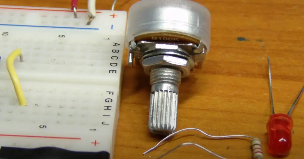
A potentiometer, also known as a “pot”, is a type of variable resistor that is commonly used in electronic circuits to control the flow of electrical current. They are used in a wide range of applications, including audio equipment, lighting systems, and motor speed controllers. Wiring a potentiometer may seem intimidating for the inexperienced, but it is actually a fairly simple process [1].
In this article, we will go over the steps required to wire a potentiometer, including the necessary tools and materials, and provide some tips and tricks to help you get the job done easily and efficiently. By the end, you will have a working understanding of how to use this versatile component to control the flow of electricity in your circuits and be equipped to tackle a wide range of potentiometer-based projects.
Whether you’re a hobbyist, a student, or just looking to improve your electronics skills, learning how to wire a potentiometer is a useful and important skill that can take your projects to the next level. So let’s dive in and get started!
What Is A Potentiometer?
It is a three-terminal device with a sliding contact, also called a wiper, that moves along a resistive element. The resistive element is typically a long, narrow strip or a coiled wire made of resistive material, such as carbon or metal.
The basic principle of a potentiometer is that it acts as a variable voltage divider. By adjusting the position of the sliding contact along the resistive element, the output voltage between the wiper and either of the outer terminals can be varied. The two outer terminals are connected to the ends of the resistive element and provide a fixed voltage across it [2].
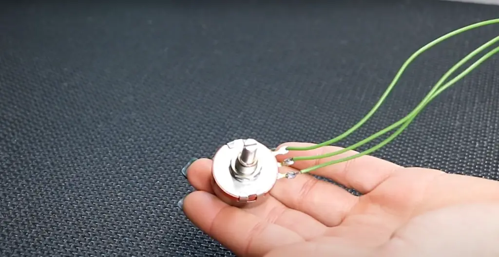
Potentiometers are widely used for various purposes, such as volume control in audio devices, brightness control in displays, and variable resistors in electronic circuits. They allow users to manually adjust and fine-tune parameters in electronic systems. The output voltage of a potentiometer can be analog (continuous range of values) or digital (discrete steps), depending on its design.
Potentiometers come in different forms, including rotary potentiometers (where the wiper is rotated using a knob) and slide potentiometers (where the wiper is moved linearly by sliding a lever or button). They are available in various resistance values, power ratings, and physical sizes to suit different applications.
Different Types Of Potentiometers:
Linear Potentiometers
Linear potentiometers, also known as linear taper pots, are the most commonly used type of potentiometer. As the name suggests, they have a linear response, meaning that the resistance changes in a linear manner as the potentiometer knob is rotated. Linear potentiometers are typically used in applications where a consistent change in resistance is required, such as volume controls in audio equipment and dimmer switches in lighting systems.
Logarithmic Potentiometers
Logarithmic potentiometers, also known as audio taper pots, have a logarithmic, or exponential, response. This means that the resistance changes more rapidly at the lower end of the potentiometer’s range, and more slowly at the upper end. Logarithmic pots are commonly used in audio circuits, where they provide a more natural and smoother response when controlling volume or tone.
Rotary Potentiometers
Rotary potentiometers, or rotary pots, are similar in shape and function to linear potentiometers, but with a rotating shaft. They are commonly used in applications where the potentiometer needs to be mounted on a panel or in a control knob. Rotary pots are available in a variety of resistance values and taper types and can be used in a wide range of applications, from motor speed controllers to guitar pedals.
Slide Potentiometers
Slide potentiometers, or slide pots, have a linear response and are operated by sliding a knob along a track. They are commonly used in applications where space is limited or where a linear control is needed, such as in DJ mixers or modular synthesizers. Slide pots are available in a range of sizes and resistance values, and can provide a reliable and compact solution for controlling various parameters in a circuit [3].
Trimmer Potentiometers
They are typically used during the construction or testing process and are often soldered directly onto a circuit board. Trimmer pots are available in a range of sizes and resistance values, and are often used in conjunction with other potentiometers to fine-tune a circuit’s overall response.
Digital Potentiometers
Digital potentiometers, or digipots, are a newer type of potentiometer that use digital signals to control the resistance. They are available in both linear and logarithmic taper types and are often used in applications where precise control over resistance or voltage is required, such as in audio processing or automation systems. Digital potentiometers offer several advantages over traditional potentiometers, including higher precision, greater reliability, and the ability to be controlled remotely through a microcontroller or other digital signal source.
Choosing the Right Potentiometer:
Resistance Matters
The amount of resistance in a potentiometer is the primary factor that determines how it will function in a circuit. Potentiometers are generally rated in ohms (Ω), so it’s important to choose a potentiometer with the correct resistance rating for your application. If the resistance rating is too high, the circuit may not function at all. On the other hand, if the resistance rating is too low, the circuit may be overloaded and fail.
Tolerance
Another important factor to consider when selecting a potentiometer is tolerance. Tolerance refers to the percentage of error between the resistance value specified by the manufacturer and the actual resistance value. Potentiometers with a high tolerance will have a wider range of resistance values, which can be useful for some applications but can cause issues for others. For example, a high-tolerance potentiometer may not be the best option for a circuit that requires precise control over resistance.
Power Rating
The power rating of a potentiometer is also an important consideration. The power rating indicates the maximum amount of power that can be safely dissipated by the potentiometer. If the power rating is exceeded, the potentiometer can become damaged or even fail completely. It’s important to choose a potentiometer with a power rating that matches the requirements of your circuit [4].
Type Of Potentiometer
There are several types of potentiometers to choose from, each with its own unique advantages and characteristics. Linear pots are the most common type, but logarithmic and digital potentiometers may be more suitable for some applications. Rotary pots are often used when precise control is required, while slide pots are perfect for space-limited designs. Trimmer pots are used for adjusting the resistance in a circuit, while digital pots can be controlled remotely and offer exceptional precision.
Physical Dimensions
The physical dimensions of a potentiometer can also play a crucial role in selecting the appropriate component. If the potentiometer is too large, it may not fit within the available space in your system. Similarly, if it is too small, it may not provide enough resistance or power handling capabilities.
Mounting Type
Finally, the mounting type of the potentiometer should also be considered. Potentiometers can be mounted in a variety of ways, including through-hole, surface mount, or panel mount. Through-hole potentiometers are designed to be mounted directly onto a PCB, while surface-mount potentiometers are smaller and are mounted onto the surface of a PCB. Panel mount potentiometers are designed to be mounted onto the front panel of a device, making them easy to access and adjust.
How To Wire Potentiometer:
1) Selecting and Preparing a Pot
- Understanding potentiometer specifications: Familiarize yourself with the key specifications of a potentiometer, such as resistance value, power rating, and taper (linear or logarithmic), to ensure you choose the right pot for your application;
- Determine the resistance value: Identify the resistance range required for your circuit. Potentiometers come in various resistance values, such as 10k ohms or 100k ohms, so choose one that suits your needs;
- Consider power rating: Determine the power rating based on the maximum power dissipation your circuit requires. Select a potentiometer with a power rating that can handle the anticipated current and voltage levels;
- Choose the potentiometer type: Decide between single-turn and multi-turn potentiometers based on the precision and resolution needed for your application. Multi-turn pots provide finer adjustments but may require more turns to reach the desired resistance value;
- Prepare the potentiometer: Remove any protective covers or packaging from the potentiometer and inspect it for any visible damage. Ensure the terminals are intact and free from debris [5];
2) Soldering Your Terminals
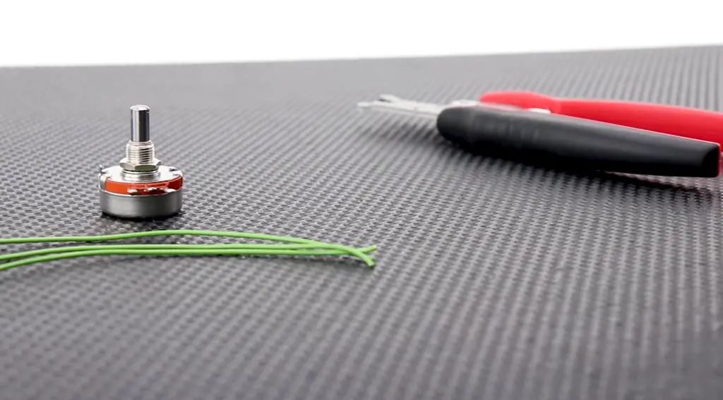
- Prepare the soldering station: Set up a clean and well-ventilated workspace with a soldering iron, solder, soldering flux (if necessary), and appropriate safety equipment like goggles and heat-resistant gloves;
- Trim and strip the wire ends: Cut the wire to the desired length, leaving some allowance for flexibility. Use wire strippers to remove a small section of insulation from the wire ends, exposing the conductive metal;
- Tin the wire ends: Apply a small amount of solder to the exposed wire ends to ensure better conductivity and easier soldering;
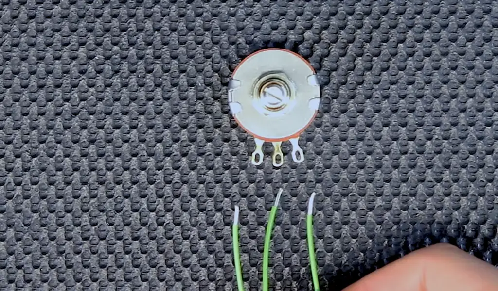
- Prepare the potentiometer terminals: Identify the three terminals on the potentiometer. If necessary, refer to the datasheet or markings on the potentiometer for terminal identification. Make sure the terminals are clean and free from oxidation or debris;
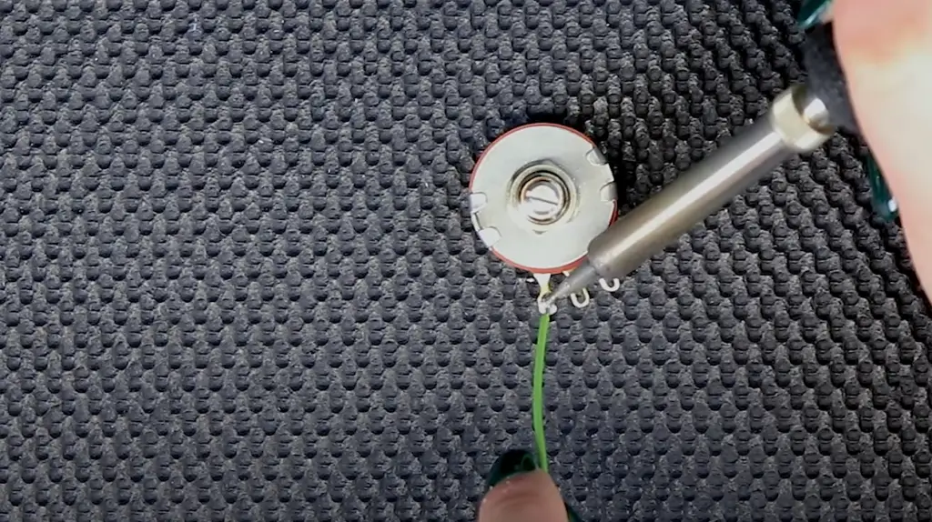
- Solder the wires to the terminals: Align the wire ends with their respective terminals and heat the terminal with the soldering iron. Apply solder to the heated terminal, allowing it to flow and create a secure connection between the wire and the terminal. Repeat this process for all three terminals, ensuring the connections are solid and free from solder bridges or cold joints;
- Insulate the connections: After soldering, use heat-shrink tubing, electrical tape, or other suitable insulation materials to cover the soldered connections and prevent short circuits or unintentional contact;
3) Using Your Potentiometer:
- Connect the potentiometer to the circuit: Identify the specific terminals required for your circuit application. Typically, a potentiometer consists of three terminals: T1, T2 (wiper), and T3. Connect T1 and T3 to the desired points in your circuit, while T2 serves as the adjustable wiper terminal [6];
- Adjusting the potentiometer: Depending on your application, turning the shaft or slider of the potentiometer will change the resistance, allowing you to control variables like volume, brightness, or sensitivity. Observe the behavior of your circuit as you adjust the potentiometer;
4) Test the potentiometer
Once the potentiometer is wired and connected to your circuit, test its functionality. Gradually adjust the potentiometer and observe the corresponding changes in the circuit’s behavior. Ensure that the resistance smoothly varies and the desired control or adjustment is achieved:
- Fine-tuning and calibration: If necessary, fine-tune the potentiometer by making small adjustments to achieve the desired resistance or control range. Calibration may be required to ensure precise and accurate adjustments;
- Mounting and securing: Once you are satisfied with the potentiometer’s performance, consider mounting it securely in your circuit or system. Use appropriate mounting hardware or techniques to ensure stability and prevent accidental movements or damage to the potentiometer;
Potentiometer Wiring Diagram:
Linear Potentiometer Wiring Diagram
Linear potentiometers are commonly used in volume and tone control applications. They have a linear taper, meaning the resistance changes evenly throughout the potentiometer’s rotation. The wiring diagram for a linear potentiometer typically consists of three terminals: the wiper terminal, the top terminal, and the bottom terminal.
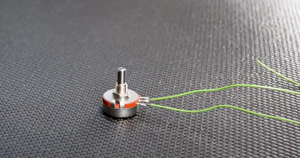
The wiper terminal is the middle terminal used for controlling the resistance. It is often connected to an output device, such as an amplifier. The top terminal is the input terminal, meaning it is the point where the voltage or signal is applied, while the bottom terminal represents the ground reference.
Logarithmic Potentiometer Wiring Diagram
Logarithmic potentiometers are often used for audio applications such as volume and tone controls. They have a logarithmic taper, meaning the resistance changes logarithmically throughout the potentiometer’s rotation. The wiring diagram for a logarithmic potentiometer is almost identical to that of a linear potentiometer, with the exception of the capacitor that is connected between the input and wiper terminals. This capacitor helps stabilize the potentiometer and eliminate noise.
Multi-Turn Potentiometer, Slide Potentiometer Wiring Diagram
Multi-turn and slide potentiometers are frequently used in precision applications, such as test equipment and calibrators. Multi-turn potentiometers require several rotations to cover the entire range of resistance, while slide potentiometers have a linear slider that is moved to adjust the resistance.
The wiring diagram for both multi-turn and slide potentiometers typically consists of three terminals: the input terminal, the output terminal, and the wiper terminal.
In a slide potentiometer, the slider is used to control the resistance, while the input and output terminals represent the points where the voltage or signal is applied and the output is taken, respectively. In a multi-turn potentiometer, the input and output terminals are flipped, meaning the input is taken from the wiper terminal, and the output is taken from the output terminal.
Troubleshooting Potentiometer Wiring
Check For Loose Connections
One of the most common issues with potentiometer wiring is loose or poorly connected wires. Loose connections can cause erratic readings or a total loss of signal. To check for this issue, inspect the wiring and make sure that all the wires are secure and tightly connected to their respective terminals. Ensure that the connections are tight enough but not too tight that they damage the wires.
Check For Shorts In The Potentiometer Wiring
The second common issue with potentiometer wiring is shorts or open circuits. These issues arise when two wires that were not supposed to come into contact do so, resulting in a short circuit, or when a wire is disconnected, leading to an open circuit.
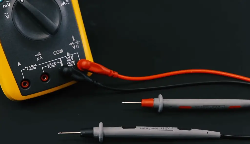
To troubleshoot these issues, measure the resistance across each wire terminal and see if there are any discrepancies in values. Then, use a multimeter in the continuity mode to check for shorts between wires. If there are any shorts or opens in the circuit, it’s necessary to make the correct alignment to prevent further damage [7].
Check For Damaged Components
The third common issue with potentiometer wiring is damaged components such as burnt resistors, or damaged diodes, transistors, or capacitors that could cause false readings, overloads or instability in the circuit operation. To check for damaged components, visually inspect the potentiometer and circuitry, and replace any components that appear damaged. You may have to use a multimeter to check the resistance values of the resistor and other components to confirm that they are working correctly.
Check For Incorrect Wiring
Another common issue in potentiometer wiring is incorrect wiring. This issue may arise when you are not sure which terminal to connect the potentiometer wire to. To avoid this problem, it is essential to read the potentiometer’s datasheet for the specific wiring scheme and guidelines. Also, drawing schematics and labeling all terminals and wire connections can help ensure the right wiring procedure.
Check The Potentiometer
If all the above steps have been followed with no success, the next step is to check the potentiometer itself. Use a multimeter to measure the potentiometer resistance, try turning the potentiometer knob or slider and observe if the resistance value changes smoothly or abruptly in steps. If the resistance value doesn’t change or changes erratically, it may need replacing. Before replacing the potentiometer, check for any signs of damage or corrosion for any terminals before the new installation to ensure that the problem is not from other areas of the circuit.
Check For Grounding Issues
The last issue to check for in potentiometer wiring is grounding issues.
To check for grounding issues, inspect the ground wire, and ensure it is tightly connected to the potentiometer and other circuit components. You should also inspect that the grounding surface is clean and clear of rust or dirt that can lead to poor grounding.
Advanced Potentiometer Wiring Usage:
Use Shielded Potentiometer Wiring
One of the most common issues that occur in potentiometer circuits is the introduction of unwanted noise or interference from external sources. By using shielded wiring, users can reduce noise and interference and improve the overall performance of their potentiometer circuit. Shielded wires have a metallic coating that encases the wire, shielding it from external noise, and ensuring smooth, stable voltage or resistance readings.
Use Dual-Gang Potentiometer Wiring
Dual-gang potentiometers are those with two sections and two separate wipers. By utilizing these types of potentiometers, users can control two separate resistive loads or voltage outputs simultaneously using the same knob or slider. This technique makes the potentiometer circuit more efficient than using two separate potentiometers, conserving space and reducing complexity.
Use Tapered Potentiometer Wiring
Tapered potentiometers are potentiometers that have different resistance values at different points of the potentiometer’s rotation. This technique allows users to achieve a more gradual change in resistance or voltage output, resulting in more precise control. Tapered potentiometer wiring is best used when a gradual change is required, such as in volume controls where a smooth increase or decrease in output is necessary [8].
Use Trimmer Potentiometers
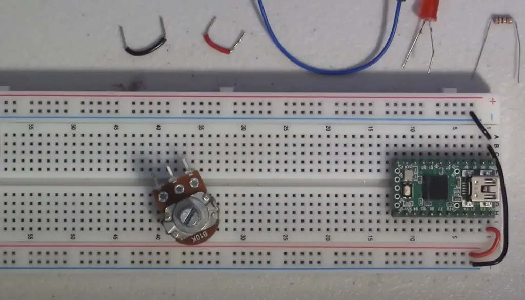
Trimmer potentiometers are miniature potentiometers that are used to calibrate or adjust other components in the circuit. They are small but precise, making them ideal for applications where precise control is needed. Trimmer potentiometers allow users to adjust the circuit’s output to the desired level, ensuring that the circuit operates correctly and efficiently.
Use Potentiometer Splitters
Potentiometer splitters are used to split the voltage or resistance output of a single potentiometer to control multiple resistive loads or voltage outputs. This technique is useful when controlling multiple circuits with one potentiometer or when space is limited. Potentiometer splitters allow for efficient control of multiple circuits without the need to use several potentiometers, saving space and reducing complexity.
Use Digital Potentiometer Wiring
In digital potentiometer wiring, users replace the traditional potentiometer with a digital potentiometer that uses a series of digital signals to control resistance or voltage. This technique is useful in applications where precise and repeatable control is required, such as in audio mixing consoles, where the level of each audio channel needs to be precisely adjusted. Digital potentiometer wiring eliminates the need for mechanical potentiometers, which can wear over time, resulting in inconsistent or erroneous readings.
FAQ
1. How should a potentiometer be wired?
A potentiometer is typically wired in a circuit using three connections: two outer terminals and a central terminal. The two outer terminals are connected to the power supply or ground, depending on the specific circuit requirements. The central terminal, also known as the wiper terminal, is connected to the circuit where the variable resistance is needed. By adjusting the position of the wiper along the resistive element, the resistance between the wiper terminal and either of the outer terminals can be varied.
2. What are the 3 pins on a potentiometer?
The three pins on a potentiometer are typically labeled as follows:
- Terminal 1 (T1): This is one of the outer terminals of the potentiometer;
- Terminal 2 (T2): This is the wiper terminal or the central terminal of the potentiometer;
- Terminal 3 (T3): This is the other outer terminal of the potentiometer [9];
3. Does a potentiometer have a positive and a negative terminal?
No, a potentiometer does not have a positive and a negative terminal in the same sense as a battery or power supply. The two outer terminals of a potentiometer are typically used to connect to a voltage source or ground, depending on the circuit requirements. The voltage applied to the potentiometer determines the range of resistance that can be obtained by adjusting the wiper position.
4. How do you wire a 3-post potentiometer?
To wire a 3-post potentiometer, you need to connect the terminals appropriately.
The specific wiring depends on the circuit requirements, but a common configuration is as follows:
- Connect one outer terminal to a voltage source or ground, depending on the circuit;
- Connect the other outer terminal to the opposite voltage source or ground;
- Connect the central terminal (wiper terminal) to the circuit where the variable resistance is needed. This can be connected to other components or used as a voltage divider;
5. How do you test a 3-wire potentiometer?
To test a 3-wire potentiometer, you can use a multimeter set to the resistance (ohms) measurement mode. Follow these steps:
- Disconnect any power supply connected to the potentiometer;
- Connect the multimeter’s positive lead to one of the outer terminals of the potentiometer;
- Connect the multimeter’s negative lead to the central terminal (wiper terminal) of the potentiometer;
- Read the resistance value displayed on the multimeter. As you adjust the wiper position, the resistance should change accordingly;
- Repeat the measurement by connecting the multimeter’s negative lead to the other outer terminal of the potentiometer to test the full range of resistance [10];
6. Is a potentiometer wire 1.5 m long?
The length of the wire used in a potentiometer can vary depending on the specific application and design. Potentiometers come in various sizes and configurations, and the length of the wire can be customized according to the requirements.
Therefore, it is possible to find potentiometers with wire lengths of 1.5 meters or even longer. However, it’s important to check the product specifications or consult the manufacturer to confirm the wire length of a specific potentiometer model, as it can vary based on the intended use and design [11].
7. What is the color code for the potentiometer wire?
The color code for potentiometer wires may vary depending on the manufacturer and specific model. There is no universal standard color code for potentiometer wires.
However, common color coding practices for potentiometer wires include:
- Terminal 1 (T1): Black, brown, or another dark color;
- Terminal 2 (T2): Red or another bright color;
- Terminal 3 (T3): Blue, white, or another light color;
8. Can we use a potentiometer instead of a resistor?
In certain situations, a potentiometer can be used instead of a fixed resistor. A potentiometer is a variable resistor, meaning it can provide a range of resistance values by adjusting the position of the wiper. By connecting the appropriate terminals, you can set the resistance to a desired value within the potentiometer’s range.
9. Why do we prefer a potentiometer with a longer wire?
A potentiometer with a longer wire is preferred in certain situations for the following reasons:
- Flexibility in placement: A longer wire allows for greater flexibility in positioning the potentiometer within a circuit or system. It provides more options for mounting or locating the potentiometer in a convenient and accessible location;
- Remote control or adjustment: If the potentiometer needs to be adjusted or controlled from a distance, a longer wire allows for the potentiometer to be placed in a remote location while still maintaining the ability to adjust the resistance value;
- Signal transmission: In applications where the potentiometer is used to control or adjust a signal, a longer wire ensures that the resistance change is accurately transmitted to the desired location, minimizing signal degradation;
10. Is a potentiometer analog or digital?
A potentiometer is an analog component. It provides a variable resistance that can be adjusted smoothly and continuously, allowing for infinite values within its specified range. The output of a potentiometer is a continuous analog signal that represents the resistance value set by its position.
In contrast, a digital component provides discrete values or states, typically represented by binary digits (0s and 1s) [12].
Examples of digital components include microcontrollers, logic gates, and digital sensors. While a potentiometer can be used in conjunction with digital components or circuits, the potentiometer itself is an analog device.
11. What is the lifespan of a potentiometer?
The lifespan of a potentiometer can vary depending on various factors, including its quality, usage conditions, and environmental factors. Generally, potentiometers have a relatively long lifespan and can endure a large number of adjustment cycles.
However, over time, factors such as mechanical wear, exposure to contaminants, and electrical stress can contribute to degradation or failure.
Higher-quality potentiometers with robust construction and better materials tend to have longer lifespans. In some applications, potentiometers can last for many years or even decades if they are well-designed, properly used, and maintained.
12. How much power can a potentiometer handle?
The power rating of a potentiometer is usually specified in watts (W) and can vary widely depending on the specific potentiometer model. Common power ratings for potentiometers range from 0.1W to several watts.
13. Can Arduino replace a potentiometer?
No, Arduino cannot directly replace a potentiometer.
While Arduino can read analog input signals through its analog-to-digital converter (ADC) pins, it does not provide a variable resistance output like a potentiometer.
14. What is the use of a 100K potentiometer:
A 100K potentiometer refers to a potentiometer with a total resistance of 100 kilohms (100,000 ohms).
The specific use of a 100K potentiometer depends on the circuit or system requirements. Some common applications include:
- Volume control: 100K potentiometers are commonly used in audio amplifiers or devices to control the volume level;
- Tone control: They can be used in audio systems to adjust the tone or equalization of the audio signal;
- Light dimming: In lighting applications, a 100K potentiometer can be used to dim or adjust the brightness of light sources;
- Sensitivity control: They are used in various sensor circuits to adjust the sensitivity or threshold level;
- Voltage divider: Potentiometers can be used as voltage dividers in circuits where a specific voltage level needs to be obtained;
15. Which wire is more suitable for a potentiometer?
Common wire types used in potentiometer applications include stranded or solid copper wires with suitable insulation, such as PVC (Polyvinyl Chloride) or Teflon. The gauge or thickness of the wire should be selected based on the current carrying capacity required for the specific application.
Thicker wires with lower gauge numbers (e.g., 18 AWG) are generally used for higher currents, while thinner wires with higher gauge numbers (e.g., 24 AWG) are suitable for lower current applications.
Useful Video: How to Wire a Potentiometer
References
- https://www.wikihow.com/Wire-a-Potentiometer
- https://www.linquip.com/blog/potentiometer-connection/
- https://www.kynix.com/Blog/How-to-Wire-a-Potentiometer.html
- https://www.instructables.com/Wire-a-Potentiometer-as-a-Variable-Resistor/
- https://www.homemade-circuits.com/potentiometers-pots-explained/
- https://www.build-electronic-circuits.com/potentiometer/
- https://www.etechnophiles.com/potentiometer-wiring-circuits/
- https://www.nextpcb.com/blog/potentiometer-wiring
- https://tipsmake.com/how-to-wire-a-potentiometer
- https://linuxhint.com/wire-potentiometer-arduino/
- https://www.techwalla.com/articles/how-to-wire-a-potentiometer-to-a-fan
- https://ask-the-electrician.com/how-do-i-wire-a-potentiometer-to-my-pump-vfd/electric/









Leave a Reply