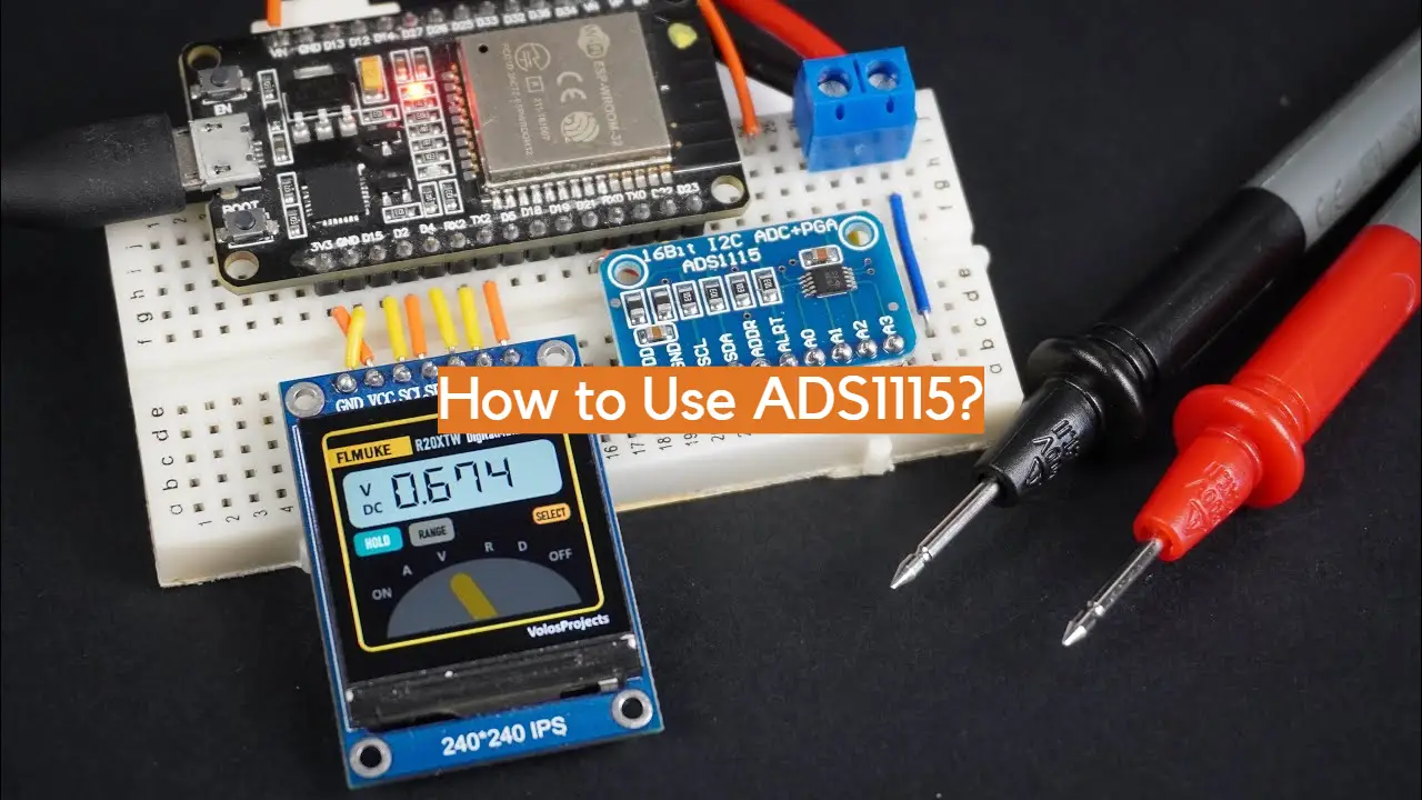
Unlocking the potential of ADS1115 is an exciting endeavor, one which requires careful consideration and a comprehensive understanding of the device. With this guide, you’ll learn how to use the ADS1115 accurately and effectively to make the most out of this incredible single-chip analog-to-digital converter. From designing your circuit to configuring the software, this guide has it all – get ready to unlock a whole new realm of possibilities with the ADS1115!
What is ADS1115 16-Bit ADC?
The ADS1115 is a 16-bit Analog-to-Digital Converter (ADC) that allows you to measure analog voltages with greater resolution than the Arduino’s 10-bit ADC can provide. The ADS1115 has a programmable gain amplifier (PGA) and an input multiplexer (MUX) for selecting between differential or single-ended conversions, as well as four conversion modes; one shot, continuous, triggered, and power down. It also includes high-accuracy references for both the VDD and GND terminals to ensure accurate measurements over varying temperature ranges.
With its wide range of features and low power consumption, it’s ideal for use in industrial data logging applications or any project requiring precise voltage measurements. The ADS1115 can be easily interfaced with an Arduino, Raspberry Pi or other microcontroller via I2C protocol to read temperature, pressure, and a variety of other sensors.
The ADS1115 is particularly useful when precise voltage readings are necessary such as in battery monitoring systems, solar panel performance tracking systems, medical instruments, and many more. With its low power consumption and high accuracy, it’s perfect for long-term data-logging applications that require accurate measurements over time.
What are the Benefits of Using the ADS1115 16-Bit ADC?
The ADS1115 offers several benefits that make it ideal for use in data logging applications or projects requiring accurate analog-to-digital conversions. Firstly, its wide input range allows it to measure voltages from 0V to 4.096V with greater accuracy than standard 10-bit ADCs can provide.
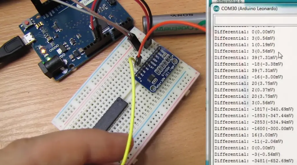
Secondly, its programmable gain amplifier (PGA) and input multiplexer (MUX) allow you to select between differential or single-ended conversions as well as four conversion modes; one shot, continuous, triggered, and power down.
Thirdly, its high-accuracy references for both the VDD and GND terminals ensure accurate measurements over varying temperature ranges.
Lastly, with its low power consumption and ease of interfacing via I2C protocol it can be used in a variety of applications without impacting battery life or requiring much programming effort.
Overall ADS1115 16-Bit ADC is a good option for obtaining accurate voltage readings in applications like battery monitoring systems, solar panel performance tracking systems, medical instruments, and more. It can be easily connected to various microcontrollers using the I2C protocol, making it a great fit for projects that require precise voltage measurements.
When shouldn’t you use ADS1115?
The ADS1115 is not suitable for applications where voltages exceed 4.096V or require very high sampling rates. It has a maximum sample rate of 860 samples per second, which may be too slow for some applications. Additionally, its low voltage range can make it unsuitable for measuring higher voltage signals such as AC power supplies and motor control systems. Furthermore, its accuracy can decrease over temperature variations making it unsuitable for certain temperature-sensitive applications.
In conclusion, the ADS1115 16-Bit ADC is best suited for lower voltage readings with greater precision than what’s available in traditional 10-bit ADCs. With its wide input range, programmable gain amplifier (PGA) and input multiplexer (MUX), high accuracy references, and low power consumption it’s a great choice for data logging applications or projects requiring precise voltage measurements. However, it is not suitable for applications with higher voltage readings or those requiring very high sampling rates.
It’s important to consider the type of application you are building and select the best ADC based on the needs of your project. The ADS1115 16-bit ADC provides excellent accuracy and resolution at lower voltage ranges, making it an ideal choice when precision is required. When used correctly, it can provide accurate measurements over varying temperatures to ensure reliable operation in your application.
ADS1115 16-Bit ADC Module Features
The ADS1115 is a 16-bit ADC module designed for high accuracy and low power consumption, making it perfect for battery-powered applications. The ADS1115 offers several features that make it ideal for a range of applications:
- Low Voltage Operation – Operating at 2.0V to 5.5V, the ADS1115 can be used in any system with voltages up to 3.3V or 5V without extra circuitry.
- High Resolution & Accuracy – With its 16-bit resolution and ±2 LSB (least significant bit) INL (integral linearity error), the ADS1115 offers exceptional accuracy and precision when measuring analog signals.
- Easy Programming – Programming is easy thanks to two types of communication protocols: I2C and SPI. Both are easy to use and can be implemented quickly in most systems.
- Low Power Consumption – The ADS1115 offers extremely low power consumption, allowing it to run for long periods on battery power or even solar energy.
- Flexible Input Range – Its input range supports both single-ended and differential inputs, making the ADS1115 perfect for a wide variety of applications such as thermocouples, bridge sensors, current sensing, and more.
These features make the ADS1115 one of the most popular ADC modules on the market today. It’s ideal for a range of projects that require precise measurements with low power consumption. Whether you need basic temperature sensing or complex current monitoring, the ADS1115 is your go-to solution.
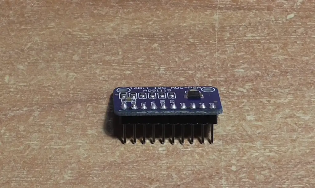
ADS1115 16-Bit ADC Module Pinout
The ADS1115 is a module that can be used to measure the voltage level present on an electrical signal. It is an analog-to-digital converter (ADC) and uses the I2C communication protocol to communicate with other devices. The pinout of this device is as follows:
- VDD: This pin connects to the positive supply voltage, typically in the range of 2V to 5V.
- GND: Connect this terminal to ground or 0V for power supply decoupling and noise reduction.
- SCL & SDA: These two pins are used to establish an I2C serial data bus between multiple devices. The address of individual devices can be set by connecting these pins together with a pull-up resistor.
- A0, A1 & A2: These are the address pins and their values determine the slave address of the device. The possible combinations are 0x48 to 0x4B depending on which pins have been connected to the ground or VDD.
- ALRT/READY: This pin is an active low output that can be used to indicate when data is ready for conversion or an alarm condition has occurred.
- ADDR: This pin allows you to connect one or more additional I2C devices for expanded functionality such as setting gain or configuring multiple ADCs in parallel mode.
- CONVST: This is the analog input high voltage endpoint commonly referred to as the conversion start point.
- SINGLE/CONTINUOUS: This pin is used to select either single-shot or continuous conversions.
- PGA/VREF: These two pins are used to set the reference voltage for analog input and gain selection by connecting a pull-up resistor.
- VIN+ & VIN- : These two pins are used for connecting an external voltage source that will be measured by the ADC. It should be connected between 0V and 2V.
The ADS1115 module is a great choice for any project requiring an accurate 16-bit reading of an analog signal, as it provides reliable performance with low power consumption in a small package. With its easy I2C interface and integrated address pins, it is an ideal choice for any application that requires precise analog measurements.
Interfacing ADS1115 16-Bit ADC Module with Arduino
Required Materials
In order to interface the ADS1115 16-bit ADC Module with Arduino, you must have the following materials to get started:
- An Arduino board such as the UNO or Mega2560
- A breadboard and jumper wires
- The ADS1115 16-bit ADC Module
- A potentiometer (5k)
Connecting the ADS1115 16-Bit ADC Module to Arduino
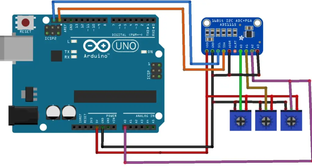
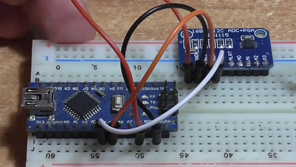
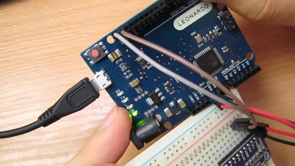
You should begin by connecting the ADS1115 module to your Arduino board. Firstly, identify all four pins on the module and connect them up as shown below:
- Connect SCL on the module to A5 on your Arduino board
- Connect SDA on the module to A4 on your Arduino board
- Connect GND on the module to GND on your Arduino board
- Connect VDD on the module to 5V pin on your Arduino board
Once you have connected up all four pins, you can then connect the potentiometer across pins 3 and 4 of the ADS1115. Now, plug in your Arduino board into a power source such as a USB port or battery pack and you are ready to begin programming!
Programming with Arduino IDE
Now that you have connected up your circuit, let’s turn your attention to writing some code. For this project, you will be using the Arduino IDE which can be downloaded for free from the official Arduino website. Open up a new sketch and begin by including the Wire library at the top:
“`
#include
“`
Now, create two constants to store the address of your ADS1115 module and the number of bytes you want to read in each transaction:
“`
const int ads_address = 0x48;
const int num_bytes = 2;
“`
Next, set up the serial connection with your Arduino board:
“`
void setup() {
Serial.begin(9600); // Set up serial connection
Wire.begin(); // Start I2C communication
}
“`
In the loop() function, start by declaring a variable to store the analog reading from your Arduino board:
“`
int analog_reading; // Variable to store analog data
“`
Now, write a Wire requestFrom command with parameters such as your device address and number of bytes to read:
“`
Wire.requestFrom(ads_address, num_bytes); // Request 2 bytes from ADS1115
“`
Once you have received two bytes of data from the module, use bit shifting and masking operations on them in order to get an accurate result. Then print out this result and delay for one second before repeating the loop():
“`
if(Wire.available() == 2) { // Check if we received 2 bytes
analog_reading = (Wire.read() << 8) | Wire.read(); // Bit shifting and masking operations
Serial.println(analog_reading); // Print the result
delay(1000); // Delay for one second
}
“`
Once you have finished writing code, upload it to your Arduino board and open up the serial monitor in order to observe the output of your program. With this, you should now be able to successfully interface the ADS1115 16-bit ADC Module with Arduino [2]!
FAQ
How does ADS1115 work?
The ADS1115 is an analog-to-digital converter (ADC). It takes in a voltage signal from a sensor and converts it to digital form so that it can be read by a microcontroller or other device. The ADS1115 has 16-bit resolution, meaning it can convert up to 65536 different values from 0V to 3.3V.
What type of sensors can I use with the ADS1115?
The ADC is compatible with almost any kind of sensor that has an output in the range of 0-3.3V, including pressure, temperature, humidity, optical and motion sensors. You may need additional circuitry such as amplifiers if you are using very low amplitude signals.
What is the maximum sampling rate of ADS1115?
The ADS1115 has a maximum sample rate of 860 Hz, meaning it can read up to 860 samples per second. The actual sample rate will depend on the chosen configuration and will be either 8-bit (128 samples per second) or 12-bit (816 samples per second).
Can I use the ADS1115 with Arduino?
Yes, you can use the ADS1115 with an Arduino board. You can use either the I2C or SPI protocol for communication between the two devices. The library for this chip is widely available and easy to install and use.
Are there any safety considerations when using ADS1115?
Yes, it is important to make sure that the power voltage supplied to the ADS1115 does not exceed its operating range. It is also worth noting that static electricity can damage the chip and cause irregular readings or failure. A proper grounding system should be used for all electronic components to avoid such issues. Additionally, when connecting sensors to the input pins of the ADS1115, make sure their voltages are within the allowed range of 0-3.3V and comply with all safety regulations. When soldering or handling any electrical components, be sure to wear proper ESD protection gear.
How to use ADS1115 with Raspberry Pi?
The ADS1115 can be interfaced with a Raspberry Pi using the I2C protocol. The Raspberry Pi has several I2C communication channels, so you will need to determine which one your ADS1115 is connected to before writing any code. Once the connection is established, you can use various libraries and packages such as SMBus or Adafruit_ADS1x15 in Python to interface with the ADC and read data from it. It is also possible to use C/C++ for this purpose. Please refer to the official documentation of your Raspberry Pi board for more details on setting up an I2C connection between it and the ADS1115.
Can I use multiple ADS1115 chips together?
Yes, you can use multiple ADS1115 chips together in a system. You will need to configure each chip differently and connect them to the same I2C bus or other communication channel. It is also important to ensure that all of the chips are powered by the same voltage so they work correctly. Additionally, make sure that your microcontroller has enough memory and processing power to handle multiple ADC readings at once. Refer to the datasheet of your particular microcontroller for more details on how many ADCs it can support simultaneously.
What are some common applications of ADS1115?
The ADS1115 is commonly used for monitoring and controlling various sensors such as temperature, pressure, humidity, optical, motion, and more in embedded systems. It is also used in robotics, wearable technology, home automation, and industrial control applications. Additionally, it can be used for data logging and recording as well as in digital signal processing. The 16-bit resolution of the ADS1115 makes it ideal for precision measurement and accurate readings.
The ADS1115 is an incredibly versatile converter that allows you to interface with almost any type of sensor while providing reliable, high-precision measurements. With its wide range of features and low power consumption, the ADC is one of the most popular components used in a variety of projects today!
What is the power consumption of ADS1115?
The ADS1115 consumes very little power, making it suitable for battery-powered applications. It has a supply current of only 150uA, and when operating in single-shot mode, its quiescent current drops to less than 10uA. Additionally, it can be powered down completely to conserve energy when not in use. This makes it an ideal choice for low-power systems where long battery life is important.
How to use ADS1115 with ESP32?
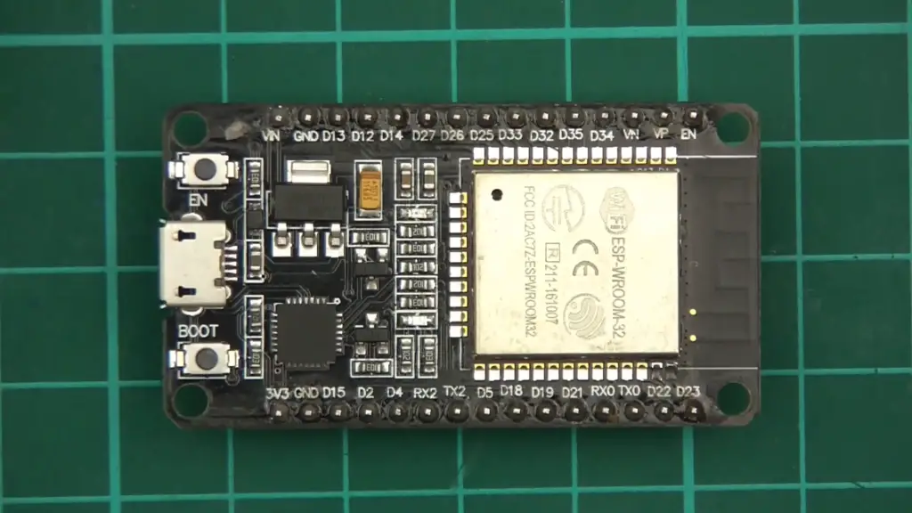
The ADS1115 can be interfaced with the ESP32 using either I2C or SPI protocols. The ESP32 has three hardware I2C channels, so you will need to determine which one your ADS1115 is connected to before writing any code. Once the connection is established, you can use either a library such as Adafruit_ADS1x15 in Arduino IDE or a package like SMBus in Python to interface with the ADC and read data from it. It is also possible to write your code for this purpose in C/C++. Please refer to the official documentation of your ESP32 board for more details on setting up an I2C connection between it and the ADS1115.
Can I use ADS1115 with a PIC microcontroller?
Yes, you can use the ADS1115 with most PIC microcontrollers. You will need to configure the ADC correctly and connect it to either an I2C or SPI bus on your microcontroller. There are libraries available for this chip that make interfacing with it easy. Additionally, if you are writing your code in C/C++ then you can follow the datasheet of the ADS1115 for more information on how to set up a communication link between it and your PIC microcontroller. It is important to note that not all PIC microcontrollers have hardware support for I2C communication channels, so please check the documentation of your particular device before attempting to use the ADS1115 with it.
Finally, make sure that your microcontroller has enough memory and processing power to handle multiple ADC readings at once when using multiple chips. Refer to the datasheet of your particular microcontroller for more details on how many ADCs it can support simultaneously.
Overall, the ADS1115 is an incredibly versatile converter that allows you to interface with almost any type of sensor while providing reliable, high-precision measurements. With its wide range of features and low power consumption, it is one of the most popular components used in a variety of projects today!
How to connect ADS1115 to Arduino Uno?
The ADS1115 can be interfaced with the Arduino Uno using either I2C or SPI protocols. The I2C interface requires only two pins (SCL and SDA) whereas the SPI interface requires four pins (SDI, SDO, SCK and SS). Once you have determined which communication protocol you will use, you need to connect the corresponding pins of your Arduino board to those of the ADS1115.
Once the connection is established, you can use various libraries such as Adafruit_ADS1x15 in Arduino IDE to interface with the ADC and read data from it. It is also possible to write your code for this purpose in C/C++. Please refer to the official documentation of your Arduino Uno board for more details on setting up an I2C or SPI connection between it and the ADS1115.
Overall, the ADS1115 is a powerful converter that allows you to interface with various sensors while providing reliable, high-precision measurements. With its wide range of features and low power consumption, it is one of the most popular components used in a variety of projects today!
How to connect a GPS sensor to Arduino?
To connect a GPS sensor to an Arduino board you will need to use the Serial Peripheral Interface (SPI) protocol. The GPS module should have four pins, and these must be connected to the SPI pins on the Arduino board.
Once the connection is established, you can use various libraries such as TinyGPS or u-blox UBX in Arduino IDE to interface with the GPS module and read data from it. It is also possible to write your code for this purpose in C/C++. Please refer to the official documentation of your Arduino Uno board and GPS module for more details on setting up an SPI connection between them.
Overall, a GPS sensor provides accurate location data that can be used in a variety of applications including autonomous drones, navigation systems, and more. It is an incredibly useful component for any project that requires precise location data! Finally, make sure that your Arduino board has enough memory and processing power to handle the multiple readings from the GPS sensor when used in conjunction with other components.
How to connect a CO2 sensor to Arduino?
To connect a CO2 sensor to an Arduino board you will need to use either the I2C or SPI communication protocols. The CO2 module should have four pins, and these must be connected to the corresponding I2C or SPI pins on the Arduino board.
Once the connection is established, you can use various libraries such as Adafruit_CCS811 in Arduino IDE to interface with the CO2 sensor and read data from it. It is also possible to write your code for this purpose in C/C++. Please refer to the official documentation of your Arduino Uno board and CO2 sensor for more details on setting up an I2C or SPI connection between them.
When using multiple ADC chips, how much memory and processing power is required?
When using multiple ADC chips, it is important to make sure that your microcontroller has enough memory and processing power to handle the multiple readings from each chip. Generally speaking, each ADC requires its own dedicated memory buffer for storing data. Additionally, if you plan on taking simultaneous readings from multiple ADCs then your microcontroller must have enough clock cycles available to handle the tasks associated with each one. It is also important to note that not all microcontrollers have support for I2C or SPI communication channels, so please check the documentation of your particular device before attempting to use multiple ADCs with it. Refer to the datasheet of your particular microcontroller for more information on how many ADCs it can support simultaneously.
Useful Video: ADS1115 16-Bit Analog-to-Digital Converter: In-Depth Tutorial with Arduino, ESP8266 & ESP32
Conclusion Paragraph
ADS1115 Analog-to-Digital Converter can be used to measure analog signals and convert them into digital format. This makes it a powerful tool for data acquisition as well as signal conditioning. Its high precision, low power consumption, and wide range of input voltage make it suitable for a variety of applications. With the help of its integrated onboard reference, differential inputs, and programmable gain amplifier, accurate measurements can be taken easily. It is also compatible with various microcontrollers including Arduino and Raspberry Pi which makes it easy to integrate with any project or system. The ADS1115 ADC offers great flexibility in capturing analog signals at low cost which makes it an ideal choice for hobbyists and professionals alike who are looking to process analog signals in their projects.
References
- https://how2electronics.com/how-to-use-ads1115-16-bit-adc-module-with-arduino/
- https://www.circuits-diy.com/interfacing-ads1115-16-bit-adc-with-arduino/






Leave a Reply