
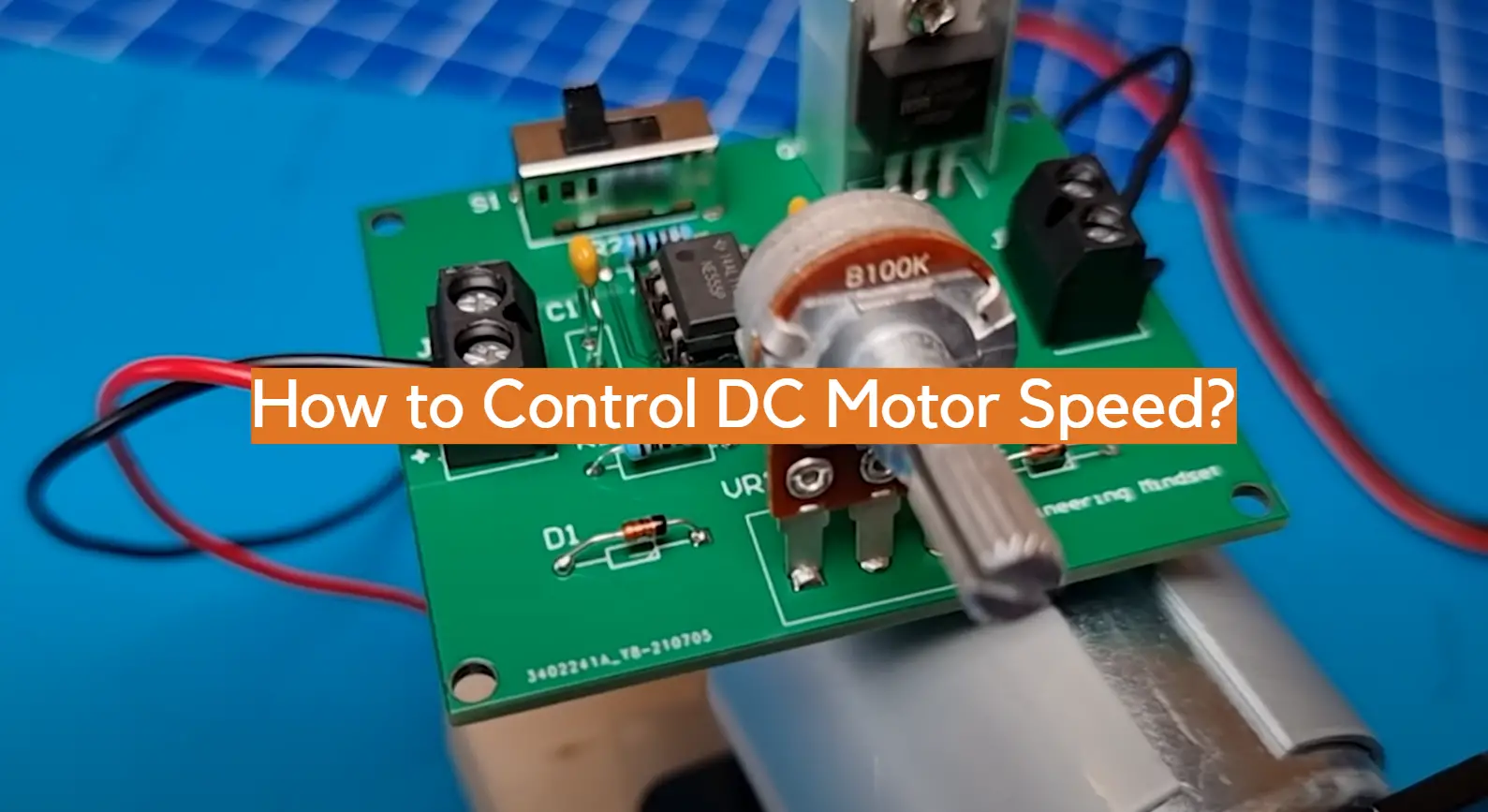
If you want to know how to control the speed of a DC motor, then this blog post is for you! We’ll go over some of the basics of how DC motors work, and then we’ll discuss various ways to control their speed. By the end, you should have a good understanding of how to use PWM signals or voltage regulators to slow down or speed up your DC motor. So let’s get started!
What Is DC Motor?
The speed of the motor is determined by the applied voltage and can be precisely adjusted by controlling its current. This makes it an ideal choice for applications such as robotics, automation, and home appliances. In order to control the speed of a DC motor, you need a controller that can adjust its currents accordingly.
There are two main types of controllers used for DC motors: PWM (pulse width modulation) and PID (proportional integral derivative). PWM controllers send pulses at regular intervals to the DC motor, which adjusts its speed accordingly. PID controllers, on the other hand, use a closed-loop control system that continuously monitors and adjusts the current being supplied to the motor in order to maintain a desired speed.
No matter what type of controller you choose, it’s important to ensure that it can handle the power requirements of your DC motor. If you don’t have enough power available, then it won’t be able to properly adjust the current and thus not achieve an optimal performance from your DC motor. Additionally, make sure that your controller is compatible with whatever software or hardware you plan to use for controlling your motors. With these considerations taken care of, you should have no problem finding the ideal controller for your DC motor.
By using a controller to adjust the current being supplied to your DC motor, you’ll be able to precisely control its speed and thus achieve optimal performance in whatever application it’s used for. With the right setup and maintenance, this can be an invaluable addition to any project. [1]
DC Motor’s Working Principle
DC motors use the process of electromagnetic induction to operate. If an electrical current flows through a conductor situated in a magnetic field, the conductor will experience an attractive or repulsive force causing it to move. This is known as the Lorentz Force Law and applies to any current-carrying conductor moving through a magnetic field. In DC motors, this effect is used to cause rotation of an armature (a coil of wire) within the motor’s permanent magnet field. The amount of torque produced by the motor depends on both the strength of the permanent magnet field and the current flowing through the armature. By varying either or both, it is possible to control the speed at which the motor spins.
Why is DC Motor Speed Control Important?
Controlling the speed of a DC motor is important for a variety of reasons. In industrial applications, such as manufacturing and production processes, it allows for precise control over the machinery and its output. This type of precision can be extremely helpful when working with delicate materials or components that require specific speeds to operate properly.
In addition, controlling the speed of DC motors also helps improve efficiency by reducing energy costs through lowering idle running times. Furthermore, when incorporated into robotics or other automated systems, having the ability to control a motor’s speed can allow for more accurate movements and smoother operation overall.
Finally, regulating the speed of DC motors can provide greater stability in a system overall as well as increase its lifespan by removing unnecessary strain on its components. [2]
Multiple Techniques of DC Motor Speed Control
Flux Control Method
This technique of DC motor speed control uses the armature circuit resistance to vary the flux produced by the field winding. This is done by controlling the amount of current that flows through the field winding. The armature voltage remains constant in this method and only a fraction of it passes through the armature winding due to a varying amount of resistance in series with it. As a result, more or less current will flow through the armature and thus more or less flux will be produced corresponding to which motor speed can be regulated accurately.
Voltage Control Method
In this method, DC motor speed control is achieved by varying applied voltage across its terminals. When supply voltage is increased above its normal value, then torque developed by the motor also increases along with the speed. As a result, its speed will increase until it reaches its no-load speed and further increasing the supply voltage will not affect its speed.
Armature Control Method
Armature control method is used when a large amount of torque is required along with precise control over the motor’s speed. This method involves varying current flowing in the armature winding by using variable resistance in series or parallel with it. When more current flows through the armature winding, then more torque can be developed at higher speeds. Similarly, decreasing armature current results in lower torque and speed of rotation as well. [3]
Field Control Method
This technique of DC motor speed control is also known as the field weakening method in which field flux is weakened by decreasing the field current. This results in a lower torque at higher speeds which is ideal for high speed applications like electric drills, etc. Also, this method has the advantage of increased control range as compared to other methods since it can operate from zero speed all the way up to rated speed.
Tacho-generator Feedback Control Method
This is an advanced technique of DC motor speed control that uses tachogenerator feedback for controlling its output speed accurately and precisely. In this method, actual motor speed is measured without contact using a tachogenerator and then this information is fed back to an amplifier circuit which compares it with reference input signal and accordingly adjusts its gain so that desired output voltage can be achieved. This provides accurate control over the motor speed and is used in applications that require high precision.
Each of these methods has its own advantages and disadvantages depending upon the application they are used in. Hence, appropriate technique should be chosen which can provide maximum efficiency along with desired results. Additionally, safety precautions should also be taken whenever working with DC motors to avoid any accidents or injuries. [4]
DC Motor Speed Control in Series Types
Using a series type DC motor offers the greatest control and power efficiency compared to other types of motors. In a series type DC motor, the armature is connected in series with the field winding. This arrangement gives greater torque and better speed regulation at all speeds. The speed of the motor can be varied by changing either the supply voltage or by varying the resistance in one or both of the windings.
When operating in a series circuit, any change in current will cause an equally proportional change in torque and speed. By increasing or decreasing resistance introduced into one or both windings, either gradually or abruptly, this will result in decreased speed for increased resistance and increased speed for decreased resistance. For example, if you want to slow down a motor, you can introduce a resistor into one of the windings. This will decrease the current flowing and reduce the magnetic field strength, causing the rotor to slow down.
In addition to resistance control, another way to vary speed in series type DC motors is through voltage regulation. By changing the supply voltage you can increase or decrease the current in both windings which will cause a proportional change in torque and speed. For example, if you want to increase speed, then increasing the applied voltage will do just that due to increased current flow in both windings.
Since varying either resistance or voltage provides reliable speed control methods for DC motors operating in series types, it is important to understand how these changes affect your motor operation. Knowing how and when to adjust resistance or voltage is key in obtaining the desired speed for your DC motor.
Shunted Armature Control
The current flowing through the armature windings creates the magnetic field that interacts with the field magnets to produce torque. The armature voltage equals the sum of the back EMF and the voltage drop across the armature resistance. This relationship is represented by Ohm’s law:
V = E + IR
where V is the armature voltage, E is the back EMF, I is the armature current, and R is the armature resistance.
If a resistor is connected in series with the armature, it is called a shunt-wound or shunt motor. Shunt-wound motors are the most common type of DC motor used for speed control. The shunt resistance can be adjusted to vary the armature current and, hence, the speed of the motor.
When using a shunt-wound motor for speed control, it is important that its operating voltage remain constant because any variation in voltage will cause a corresponding change in back EMF, which affects speed. Therefore, an adjustable power supply or regulator should be used with a shunt-wound motor to ensure that the required level of voltage is applied at all times. This will enable the motor to run at a steady speed despite changes in load or system disturbances. Additionally, good ventilation and heat dissipation practices must be implemented to prevent the motor from overheating.
By adjusting the shunt resistance, it is possible to precisely control the speed of a DC motor. However, this method does not offer the best efficiency and can lead to power loss due to heat generated by the shunt resistor. As such, this approach should only be used when precise speed control is required without regard for energy conservation. [5]
Field Diverter Technique
Field Diverter Technique is a control methodology used to alter the speed of DC motors. This technique works by controlling the current in the field windings of the motor, which controls both its torque and speed. By adjusting the current in these field windings, the back EMF can be shifted up or down, causing an increase or decrease in motor speed.
The Field Diverter Technique provides precise and accurate control over motor speeds with minimal power consumption. Furthermore, this technique allows for smooth and efficient acceleration and deceleration of a motor. In some cases, it may also be combined with other methods such as pulse width modulation (PWM) for optimal performance. Due to its efficiency and low cost, the Field Diverter Technique has become a popular choice for controlling DC motor speed in various applications.
To use the Field Diverter Technique, one must first install field diverters, which are components that regulate the flow of current through the motor’s field windings. Once installed, an external power source can be used to adjust the speed of the motor by changing the amount of current passing through the field diverters. It is important to note that this method can be used with both series and shunt motors but may require additional steps depending on which type is used.
Overall, the Field Diverter Technique provides an effective way to control DC motor speeds while maintaining accuracy and efficiency. The simplicity of installation and cost-effectiveness makes it ideal for many applications. Furthermore, by combining it with other control techniques such as PWM, one can optimize performance and achieve the desired motor speed.
Controlling of Tapped Field
DC Motor is done by varying the tapped field current or armature voltage while keeping a constant speed. This type of motor has an added advantage of having variable speed and can be used in applications that require variable speed control.
To vary the tapped field current, a transistorized DC (TDC) amplifier circuit is used which consists of transistors, resistors, capacitors and diodes. The TDC amplifier converts a small input signal into a large output signal which is applied across the tapped field winding for controlling its current. Resistance connected in series with the tapped field winding limits the current to safe value and also provides high starting torque at low speeds. Potentiometer connected across the dc supply permits to adjust maximum tapping current. A simple method of controlling the speed is to vary the applied voltage across the armature by means of a rheostat or SCR (Silicon Controlled Rectifier). An electronic regulator called chopper can also be used for varying the voltage across the armature.
Armature Resistance Control Method for DC Shunt Motor
The armature resistance control method of controlling the speed of a DC shunt motor is one of the most common and simplest techniques used to adjust motor speed. By adding resistance in series with the armature circuit, the current through it can be reduced, thus slowing down the motor. This technique is especially useful for low-power motors because it requires no external power source and does not affect other parameters such as efficiency or power factor.
The disadvantage of this method is that it is inefficient since some energy is lost in the resistors due to heat dissipation. Additionally, adding too much resistance can cause excessive heating which will eventually lead to damage to the motor winding insulation. For this reason, armature resistance control must be used carefully and only for short-term speed adjustments.
Another limitation of the armature resistance control method is that it cannot be used to reduce the speed of a motor below its base speed, since at some point, adding more resistance will not further reduce the current. As such, this technique should be used when only small increases or decreases in motor speed are needed. In cases where more accurate and predictable performance is required, other techniques such as field flux control or variable frequency drives may be preferable.
By using armature resistance control effectively and safely, DC motors can easily be adjusted to run faster or slower depending on the application requirements. This makes it an excellent choice for applications where precise and economical speed adjustment is needed. [6]
FAQ
What are the methods of speed control of a DC motor?
The speed of a DC motor can be controlled through various methods, including the use of mechanical friction brakes, electronic drives, PWM or pulse width modulation techniques and varying field circuit resistances. Each method has its own advantages and disadvantages depending on the application. Mechanical friction brakes are the simplest form of speed control as they utilize physical forces to slow down the motor’s rotation. Electronic drives allow for precise control over the speed by varying voltage levels sent to the motor; this is often used in robotic applications. Pulse width modulation (PWM) also uses voltage to adjust speed with frequency variations; PWM is preferred for robotics due to its faster response time compared to other methods. Finally, varying field circuit resistances allows for more fine-tuned speed control but with a lower power output. All these methods can be used to maintain and regulate the speed of any DC motor.
Can the speed of a DC motor be easily controlled?
Yes, the speed of a DC motor can be easily controlled. There are several methods which can be used to control DC motor speed such as using PWM signal, changing applied voltage or current, and using an H-bridge circuit. Pulse Width Modulation (PWM) is a method that applies varying amounts of power to the DC motor over time. This technique is usually employed when precise control of the motor’s speed is desired and it involves switching the electric signal on and off at a high frequency while varying the duty cycles of these signals with respect to each other. This will cause the average power supplied to change thus adjusting the rotational speed accordingly. Another way to adjust a DC motors speed is by altering the applied voltage and current. This is commonly done through linear regulation, which adjusts the power supply to the motor according to a reference signal. Finally, an H-bridge circuit can be used for speed control by allowing the application of varying amounts of voltage or current across two terminals connected with an H-bridge circuit. By changing the direction of current flow or its magnitude, it is possible to adjust the speed of a DC motor accordingly.
How do you control the speed of a 24vdc motor?
The speed of a 24VDC motor can be controlled using a variety of methods. The most common method is to use pulse width modulation (PWM) to adjust the power being applied to the motor. PWM works by varying the duty cycle, or amount of time that power is applied to the motor, in order for it to reach its desired speed. Additionally, you can also use variable resistors such as potentiometers and rheostats to control the voltage level being sent to the motor, thereby controlling its speed. Finally, you could also use a combination of both PWM and variable resistors in order to fine-tune your desired speed.
What is the rpm of a 24V DC motor?
It is important to note that the voltage applied to a DC motor has a direct correlation with its operating speed; increasing the voltage will result in an increase in speed, while decreasing it will decrease the speed of the motor. It is also important to ensure that your power source for the motor is capable of supplying enough current for its operation as well. If not, you could end up causing damage to both the motor and power source due to overheating or overloading.
How can I increase the speed of my 12v DC motor?
You can increase the speed of your 12v DC motor by increasing the voltage sent to it. This can be done using a step-up converter that will boost the voltage from 12V to 24V or higher. Additionally, you can also use pulse width modulation (PWM) to achieve higher speeds without directly increasing the voltage. PWM works by rapidly switching the power on and off, thereby controlling the amount of power being sent to the motor and allowing for finer control of its speed. Finally, if you have access to a variable-voltage transformer, you can use this as well in order to precisely set your desired operating speed.
Can any DC motor be variable speed?
The answer to this question depends on the type of DC motor you have. A brushed DC motor can be controlled by varying the voltage applied, however brushless motors require a speed controller to vary the output speed. Brushed motors are relatively easy and inexpensive to control, with mechanical components such as gears or pulleys being used. These methods tend to suffer from wear and tear over time, so they may not be suitable for continuous operation. Brushless DC motors must use an electronic speed controller (ESC) to change the speed of rotation. An ESC converts electrical energy from a power source into mechanical energy that turns the motor’s shaft at a desired speed. The ESC is typically battery-powered, but it can also be powered by other sources such as solar cells or mains power.
Useful Video: How To Make Simple DC Motor Speed Controller Circuit
Conclusion
By controlling the speed of a DC motor, you can customize the performance of your equipment for specific applications. The most common ways to regulate a DC motor’s speed are by changing its voltage, changing its current, and changing the number of poles in its stator winding. By investing in quality components and proper wiring techniques, you can be sure that your equipment will run safely and efficiently at any desired speed. With the right choice of components and some knowledge on how to control DC motor speed, anyone can get their machine up and running faster than ever before.
References
- https://www.elprocus.com/what-are-the-best-ways-to-control-the-speed-of-dc-motor/
- https://robu.in/speed-control-of-dc-motor/
- https://www.instructables.com/Controlling-Motor-Speed/
- https://www.electricaleasy.com/2014/01/speed-control-methods-of-dc-motor.html
- https://www.aspina-group.com/en/learning-zone/columns/what-is/011/
- https://www.circuitbasics.com/introduction-to-dc-motors-2/