
Are you ready to take on the challenge of building your very own Arduino Ball-Balancing Robot? With the rise of robotics and technology, learning how to create an Arduino ball-balancing robot can be a fun and exciting way to explore the world of robotics. In this blog post, you will get access to all the tips and tricks you need in order to have a successful build. So get ready for an epic journey into the world of Arduino Ball-Balancing Robots!
What is an Arduino
It contains an Atmel AVR processor and a set of input/output pins that allow it to communicate with various electronic components such as sensors, motors, relays, LCDs, etc. The board is programmed with the Arduino Software (IDE), which allows you to write and upload code to the board. With this software you can create custom programs that interact with your hardware project in ways limited only by your imagination!
The Arduino platform simplifies programming of electronics by providing basic building blocks that you can use to easily create complex designs. For example, you can have a light blink when motion is detected or receive data from a remote sensor. You can also use the Arduino to control motors, read analog and digital inputs, or send data to a computer or other devices. The possibilities are endless thanks to the simple yet powerful programming language. [1]
Assembly Instructions
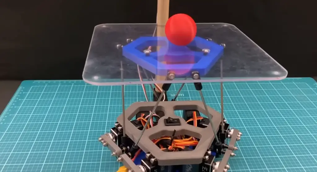
The Arduino ball-balancing robot is a good example of how this technology is used in robotics projects. It can be used to create a self-balancing robot that can move around and react to its environment. The Arduino board is used as the brains of the robot, while motors and sensors provide the necessary inputs and outputs for it to maneuver. By programming the board with a few simple instructions, you can easily control how your robot moves and reacts within its environment.
Make a base platform
First, you will need to make a base platform for your robot. This can be as simple as a flat piece of wood or acrylic, or you can use something more elaborate such as an aluminum frame. Whatever material you decide to use, make sure it is strong enough to support the weight of the robot and its components.
Once you have chosen your material, cut it into the desired shape and size using a saw or cutter if necessary. Depending on your design, you may also want to drill some holes for mounting components later on.
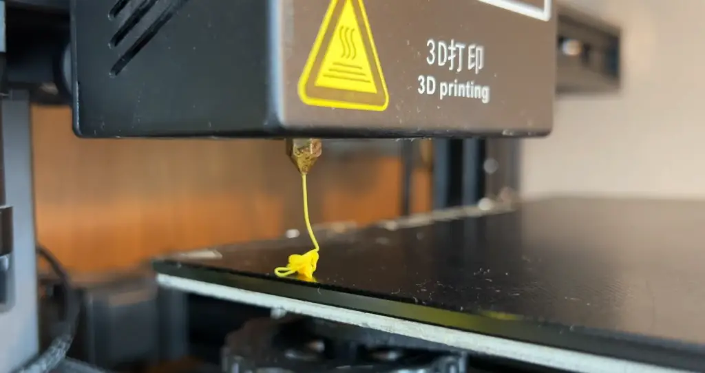
3D print the parts
Next, you will need to 3D print the parts for your robot. You can either design these yourself or download pre-made models from various websites such as Thingiverse. Once you have chosen the models and downloaded them, you can use a 3D printer to print out all of your parts. Depending on the complexity of your robot, this could take anywhere from several minutes to several hours. Once finished, you should have all the components necessary for assembly! Parts should include a ball, mount, a base plate and a form.
It’s not necessary for you to print the ball as you can easily find one at a hobby store. But a self-printed one will be able to fit your robot perfectly and make assembly much easier.
Assemble the ball
The star of your show will be the ball. If you choose to print your own, you will need to do some sanding and filling of the print lines to make it smooth and round. If you bought one from a store, you should check it for any defects or bumps that could affect your robot’s performance.
Once the ball is prepared, assemble it with the mount using screws. Make sure that all parts are secured firmly as this will be crucial for our ball-balancing robot’s performance.
Add inserts into the printed parts
Next we will check the other parts for any defects and then add inserts into the holes of the base platform frame, base plate, cover plate, and four center markers. You can use screws to secure them or use a hot glue gun to quickly attach them in place. As you can see, not all parts require inserts, as some of them are designed to hold the components in place without any additional tools.
Create the microcontroller circuit
Now it’s time to add some brains to your robot. To create the microcontroller circuit, you will need an Arduino board and all of its accompanying components, such as resistors, capacitors and transistors.
We will use a Teensy 4.1 microcontroller board as the main processor for our robot and connect it to a power supply with a 5V regulator. You will need to download Teensyduino, an extension of the Arduino IDE, in order to program it.
While you’re at it, you can modify your microcontroller a bit. Cut the VIN to USB trace on the back of the Teensy board so that it can receive power from an external source. This will allow you to attach an external power source, such as a battery or solar panel, and make your robot more energy-efficient. In our case it’s a 7.4V LiPo battery.
Attach a servo controller
The next step is to attach a servo controller. This will be used to manage the movement of the servos and keep them in sync. We recommend using a Polulu Maestro as it has plenty of power output and is easy to use. Just connect its input pins to the Teensy board’s digital output pins, and you’re ready to go!
The 6 pin Polulu Maestro is responsible for controlling the servos, which connect to the Maestro, which in turn connects to the Teensy via its RX and TX pins. The Maestro is the only component that directly connects to the 7.4V battery, and it has a 5V regulator that will power the Teensy. To connect the Teensy, two wires (+5V and ground) are soldered to the Maestro.
To set up the Polulu Maestro, one needs to download the Maestro Control Center software and verify/change two settings. After downloading the software and connecting the Maestro, plug in one of the servos and move it around from the software to check if the board works. Then go to the Serial Settings tab to verify/change two settings – Serial mode and CRC.
Finally, to modify the Maestro, one needs to solder a wire connecting the VIN to servo power (+). This allows the servos and the Maestro board to be powered by the 7.4V battery.
Install a camera
Your little robot will need something to use as eyes. That’s where the camera comes in. You can either buy a ready-made one or build your own using an Arduino Camera Shield and a microSD card reader. For our project, we’ll be using the Pixy2 camera, which is a high quality image sensor with excellent low light performance.
To view the camera footage and set up object detection, one needs to download Pixymon v2. The camera should be plugged into the computer, and Pixymon should be used to verify that it works. Object recognition can be tested by setting up a random object to be detected, and the manual method is recommended for setting up object detection.
We will need to power the Pixy2 camera into the computer via micro USB as the battery isn’t reliable this time. The Teensy, the Pololu Maestro, and the servos will be powered by the 7.4V battery whenever the robot is in use, while the camera will be powered by the computer.
Install the Arduino libraries
You’ll need to install a few libraries for your robot’s components.
The first library is for the Pololu Maestro, and the second library is for the Pixy2 camera. These libraries need to be installed to ensure that the build works as intended.
Build the circuit
Now that you have all the components and know how to set them up, it’s time to build the circuit.
To create the full circuit for the robot project, you will need the modified Teensy 4.1 microcontroller, modified 6-pin Polulu Maestro servo controller, Pixy2 camera, 3.3 to 5v logic level converter, half proto board, and a switch. The first three components were explained earlier, while the logic level converter (LLC) and servos are the remaining ones. The LLC steps down the logic level from 5V to 3.3V to connect the Maestro’s RX and TX pins to the Teensy, which uses 3.3V logic level. The six high-speed JX CLS6336HV servos connect to the six channels on the Pololu Maestro.
You can find the actual schematics for this project online. Begin by connecting the power supply to the proto board, then connect all components except for the servos in their respective positions. Double-check before you solder everything together, and make sure all connections are correct.
Solder the Teensy and LLC onto the protoboard, and connect the Maestro and Pixy to the Teensy via wires. Use header pins for removable electronics, heat shrink tubing to insulate wires, and a multimeter to test connectivity. Servo extension cables allow for plug-and-play functionality, making troubleshooting easier. The switch turns the robot on and off by completing the circuit on one lead of the battery, and the ground pins on all components should be connected together for common ground.
Assemble the base
Next, we need to put together the base of our robot. The base is composed of two parts: the platform and the legs.
To assemble the base of the robot, you will need six servos, a base plate, a pixy2 bottom mount, eight M3 x 5mm screws, and four M3 x 15mm screws. The assembly process involves first mounting the pixy2 bottom onto two of the servos using the M3 x 15mm screws and then attaching them to the front of the base plate. The remaining four servos should be screwed onto the other sides of the base plate using the M3 x 5mm screws.
Next, the half protoboard should be screwed onto the top of the base plate, which requires removing the teensy 4.1 and LLC to access the holes on the protoboard. The polulu maestro should be hot glued onto the base plate, and finally, the six servos should be connected to the six channels on the maestro in a specific order.
Cover should be installed next, and this is where the plexiglass or acrylic cover for the robot comes in. The cover should be slightly larger than the base plate to ensure a snug fit, and it should be secured with double sided tape or hot glue along the edges. You will need 12 m3 x 5mm screws, and a switch that should be glued onto a cover plate.
Assemble and install servo arms
To assemble the servo arms, you will need six 3D printed links, six 25T servo discs, 18 m3 lock nuts, six m3 x 120mm pushrod connectors, 12 22mm long m3 tie rods, and 12 m3 x 12mm screws. Begin by screwing each servo disc onto each link using two locknuts and two m3 x 12mm screws per disc. Assemble the six tie rods by attaching two tie rod ends to each pushrod connector, then screw the other end of each link onto one of the ends of the tie rods using an m3 x 22mm screw and a locknut for each link to form six servo arms.
To mount the servo arms onto the servos, an Arduino sketch must be uploaded that will move all the servos to their home location. Make sure the battery is plugged in and the switch is turned on before uploading the sketch to the teensy. Screw the servo arms onto the servos using m3 x 12mm screws, ensuring they are as close to perpendicular to the servos as possible. Fine tuning of the arms will likely be necessary.
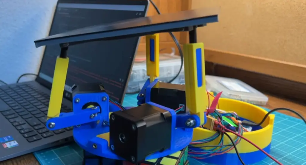
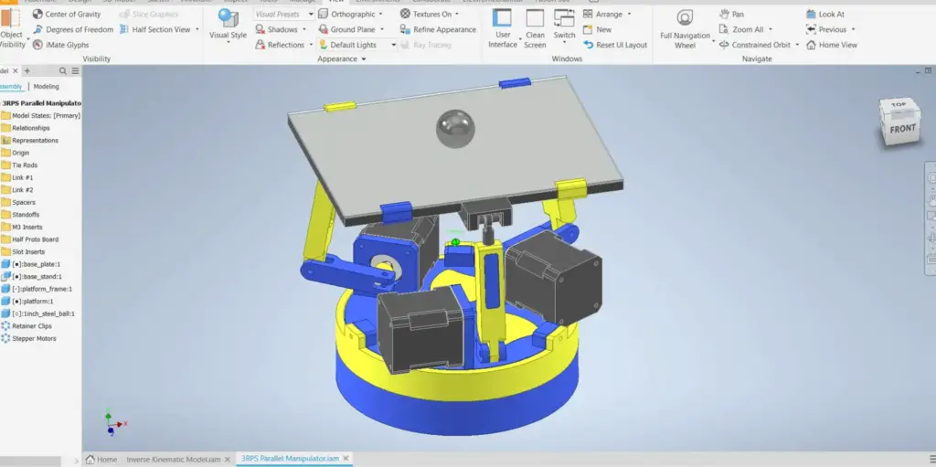
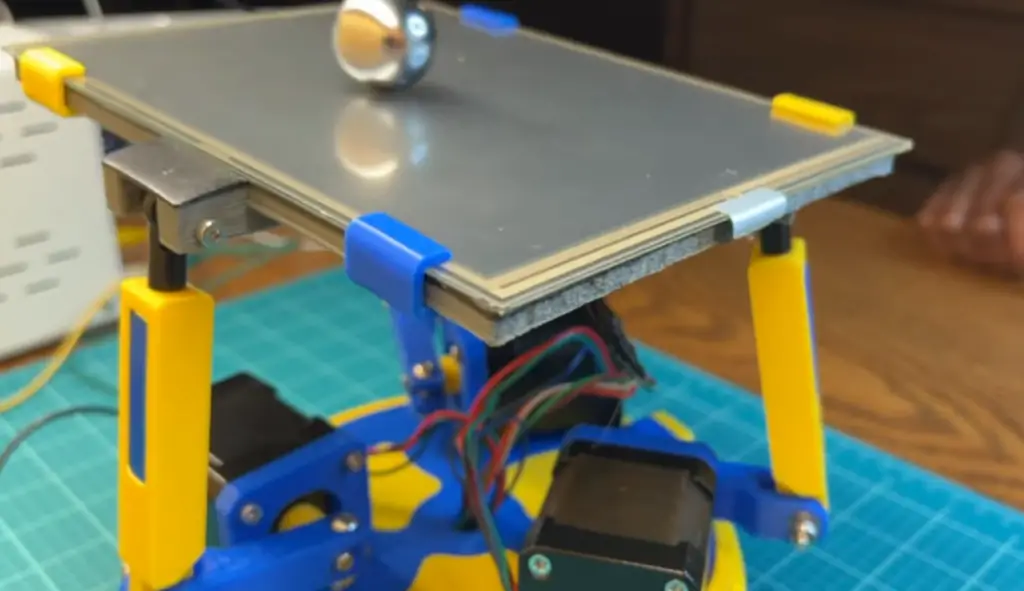
Build and attach the platform
Now, the platform needs to be built and attached to the robot. To build the platform for the robot, you will need a polycarbonate platform, a platform frame, m3 x 20mm button head screws (x3), m3 lock nuts (x3), and m3 x 5mm standoffs (x3). Attach the polycarbonate platform to the printed platform frame using the m3 x 20mm screws and locknuts. Remember to add a 5mm standoff on each screw in the space between the platform and the platform frame.
Next, attach the platform to the main body of the robot using m3 x 5mm standoffs (x6) and m3 x 14mm screws (x6). Attach each m3 x 14mm screw onto the end of each servo arm. On the other side of the screw, screw on each m3 x 5mm standoff. Finally, screw the servo arm onto the platform frame where the threaded inserts are located.
Attach a camera mount and a camera
The camera mount and the camera are necessary components for the robot since it allows us to see where we’re going. First, a wooden dowel is cut to 19 inches and attached to the Pixy2 bottom mount using two #6 screws. Then, the Pixy2 top mount is screwed onto the other end of the dowel with two #6 screws.
Next, the Pixy2 camera is attached to the top mount using three M3 x 30mm screws, three M3 x 10mm standoffs, and three M3 lock nuts. It is important to ensure that the camera has a good view of the platform by checking the footage on Pixymon. If the entire platform is not visible, the placement of the top mount should be adjusted.
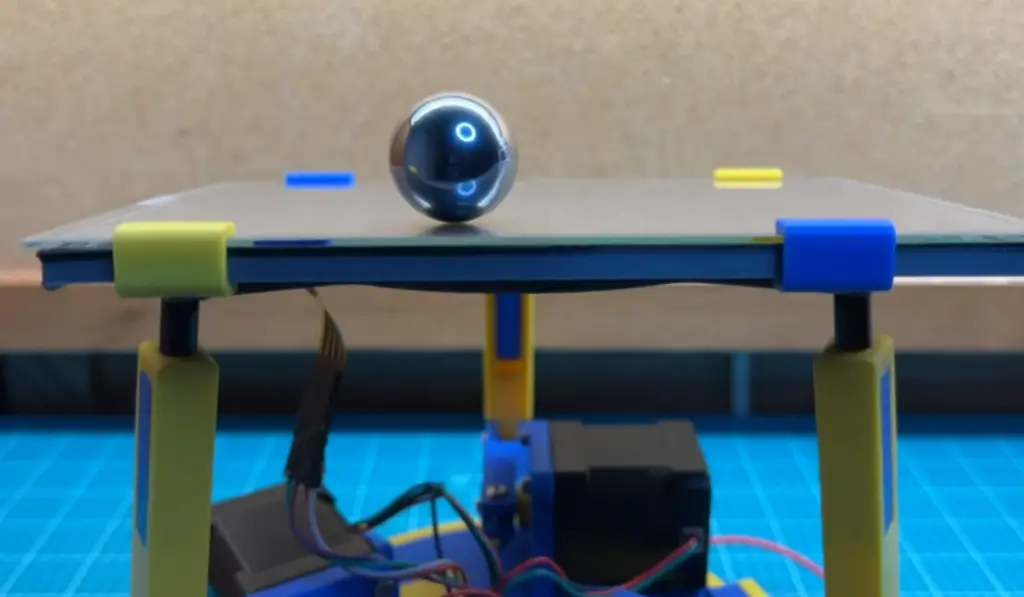
Teach the robot to detect the ball and calibrate the platform
Once the robot is fully constructed and all components are working, it’s time to teach the robot to detect the ball. There are many guides on how to do this that can be found online. Generally, the process of teaching the robot to detect the ball involves uploading a sketch onto the teensyduino and running some code. The code will allow us to see what the Pixy2 camera is seeing in real time, allowing us to adjust its position if needed.
After teaching Pixy2 about your ball, you must calibrate your platform for optimal performance. To make the ball balancing program function accurately, two values are required: the center of the platform from the camera’s view and r_platform, which assists in determining if the ball is on the platform. The solution involves using red 3D-printed center markers placed on each corner of the platform using m3 x 5mm screws. The pixy cam should recognize the markers as the ball that was previously trained to identify in the prior step.
It is necessary to verify that the pixy cam can recognize each center marker by checking the camera footage on pixymon to ensure that only four signatures for the four markers are detected. If more or less than four markers are detected, the program will not function. The next step is to download the Arduino program and replace the offset values from 0 to the values discovered in step 13. After that, the sketch should be uploaded.
Finally, the program will move each servo to its home position and display values on the serial monitor. With this, the ball balancing program will be operational.
Upload the code
Lastly, the code for the ball-balancing robot needs to be uploaded to the Arduino. This code will allow us to control all of the components of our robot, such as the servos and sensors. To upload code, again, you’ll need an Arduino IDE that can be downloaded from the official website. Once installed, open up the folder containing your source code and select “Upload” under Sketch in the menu bar. The Arduino will then compile and upload your program onto your robot. If successful, you should see a message confirming that it has been successfully uploaded. [2]
FAQ
How does an Arduino-based balancing robot work?
The main component of any Arduino-based balancing robot is an Arduino microcontroller which functions as its “brain”. This microcontroller can read data from various sensors including accelerometers, gyroscopes, and infrared range finders. All of this data is then sent to the Arduino which uses the information to calculate how much effort and power needs to be applied to each wheel in order for it to move and remain balanced.
The robot also relies on a variety of other components such as motors and wheels, batteries, a frame, and various other parts like an IR receiver or Bluetooth module. This combination allows the robot to maneuver accurately while staying upright with minimal power consumption.
Which motor is best for a self-balancing robot?
The stepper motor is the most suitable for a self-balancing robot. It has high resolution, accuracy and stability which are essential for controlling its movement. The stepper motor offers precise control to keep the ball balanced on top of it. Additionally, the stepper motor requires minimal maintenance and is highly efficient, making it an ideal choice for this type of project.
What is a robot that balances on a ball?
A that balances on a ball is a type of machine that utilizes a computer and locomotion system to about and remain balanced atop a. This can be achieved through use of an Arduino, sensors, motors, gyroscopes, and other components. The user must program the Arduino board with code to enable the robot to balance itself when moving around on top of the ball.
Useful Video: I Built a Ball Balancing Robot
Conclusion
Arduino ball balancing robots are a fun, educational project that can help teach basic robotic concepts in a hands-on way. This guide has provided an introduction to Arduino ball balancing robot projects from start to finish. We have discussed the basics of building a robotic platform using an Arduino, including the necessary components and wiring. We have also discussed how to program a ball-balancing robot using various sensors and servo motors.
By understanding the basics of how robots work and how to program them, you’ll be able to create more complex robots as your skills improve. We hope this guide has given you all the information you need to start building your own Arduino ball balancing robot! Happy creating!
References
- https://docs.arduino.cc/learn/starting-guide/whats-arduino
- https://www.instructables.com/Ball-Balancing-Robot/