Take your electronics projects to the next level with this advanced PIC frequency counter project. You’ll learn how to use a single IC timer and some easy-to-find components to construct an inexpensive digital frequency display that is both accurate and reliable. This project will be a great enhancement for any electronics hobbyist, giving them the ability to accurately measure and monitor frequencies in their creations. With this comprehensive guide, you’ll find out how to create a functional frequency counter using a PIC microcontroller.
What is PIC Frequency?
PIC (Programmable Interval Controller) Frequency is an electronic device that can be programmed to control frequency in AC electric motors. It works by providing a variable frequency of alternating current to the motor, allowing it to adjust speed and torque as needed for various applications. PIC Frequency offers users precise control over the speed and torque of their motor, making it ideal for applications like conveyor systems, industrial machinery, and even computer cooling fans.
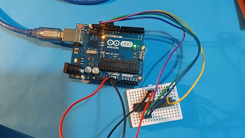
Additionally, PIC Frequency devices are incredibly reliable and require very little maintenance or repairs. This makes them perfect for long-term use in any industrial setting. With its intuitive programming interface and range of available features, PIC Frequency is one of the most popular solutions on the market today.
By using specialized tools like oscilloscopes, power analyzers, or tachometers, technicians can easily measure frequency and analyze performance in real-time. This data can then be used to ensure that the motor is running at the correct speed and taking advantage of all available torque. Proper measurement of PIC Frequency can help prevent costly repairs or downtime due to incorrect settings. Understanding how to properly measure this type of frequency is essential for any experienced engineer or technician.
What is a PIC Frequency Counter for?
A PIC frequency counter is a tool used for measuring the frequency of an alternating electric current. It is typically used to measure the frequencies of oscillators, sine waves, and other electrical signals. The counter works by counting the number of pulses in a given period of time and then converting this count into hertz (frequency).
By using a PIC frequency counter, you can accurately measure frequencies from anywhere between 0 Hz up to 100 MHz. This makes them ideal for use in laboratories or other environments where precise measurements are needed. They are also small and lightweight which makes them portable and easy to use. In addition, many models come with features such as auto-ranging, displays that can be customized to show different formats like dials or bars, and memory to store readings.
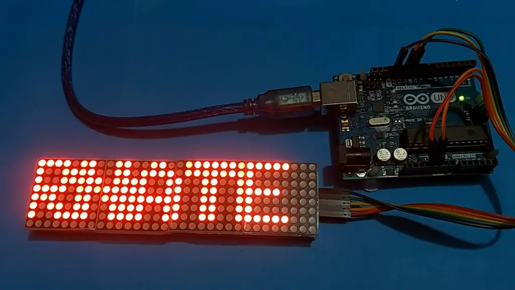
PIC frequency counters are used in a wide variety of fields such as audio engineering, telecommunications, radio broadcasting, electronics design/manufacturing, automotive diagnostics, and more. They can be used to measure the frequencies of sound waves for recording or playback purposes, test transmission signals for quality control purposes, check the tuning of antennas or other RF systems for optimal performance and even verify that parts being manufactured are working correctly. With their accuracy and range of capabilities, PIC frequency counters are essential tools for many professionals.
Specification: LCD frequency counter circuit
Description
The LCD frequency counter circuit is designed to accurately count the frequency of a signal. It uses an integrated LCD for easy readability and features a wide range of input voltage frequencies, making it suitable for various applications. The device can be powered using either AC or DC power sources. Its accuracy is ensured by its low-power consumption design, which ensures long battery life and reliability in varying temperatures and environments.
This frequency counter includes a backlight that can be turned on or off when needed, allowing users to easily view readings even in dimly lit areas. Additionally, the device contains several buttons that allow for manual input of data into the display, such as maximum or minimum values needed for specific measurements. The LCD frequency counter offers excellent value and is a great choice for any DIY project or hobbyist.
Hardware
The LCD frequency counter comprises a variety of components, including an integrated LCD display, several buttons for manual input, and a wide range of voltage frequencies. Additionally, the device includes backlighting that can be turned on or off with the press of a button.
Software
The software for this LCD frequency counter is designed to accurately count the signal frequency and store it in memory for future readings. It also offers user-friendly settings such as maximum/minimum values and alarm settings that can be customized according to individual preferences. The device supports multiple languages, allowing users from different regions to read data without any difficulties [1].
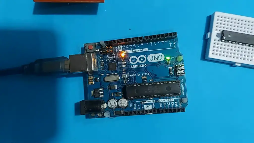
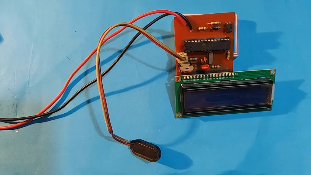
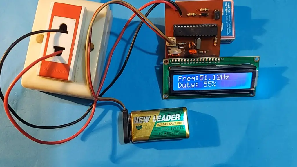
Frequency Counter Using PIC16F628A (with Prototype PCB and Built in Crystal Oscillator) for HAM Shacks
Step 1: Gathering the Parts
To make a frequency counter using the PIC16F628A microcontroller, you will need to gather some components. You can purchase most of these directly from your local electronics store:
- PIC16F628A – The main microcontroller component for controlling all operations
- Prototype PCB (PCB) – This is what the circuit board will be made on, it acts as a platform for all components to be soldered together
- Built-in Crystal Oscillator – This oscillator provides timing pulses for the microcontroller, and helps synchronize its operation with other devices in the shack
- LCD Display – For displaying any information related to frequency or time
- Buttons/Switches – To control the frequency counter and provide user input for frequency settings
- Miscellaneous Connectors, Wires, etc. – All necessary connectors, wires, and other materials to safely power up and connect all components.
Step 2: Building the Circuit
Once you have gathered all of the components listed above, it’s time to start building the circuit for your PIC16F628A Frequency Counter project. This will involve soldering all of the parts together on a prototype PCB board according to a predetermined schematic layout. The exact details of this process are beyond the scope of this article, but there is plenty of information online that can help with this step.
Step 3: Programming the Microcontroller
The next step in the process is to program the PIC16F628A microcontroller with your desired code. This can be done using any number of programming languages, such as assembly language, C++, or even Visual Basic. Programming a microcontroller requires a fair amount of knowledge and experience, so it’s best to research this step thoroughly before attempting it.
Step 4: Testing the Frequency Counter
Once you have successfully programmed your microcontroller and connected all components on the prototype PCB board, you are ready to start testing your frequency counter. This will involve connecting it up to a test signal generator and running tests at various frequencies and settings. All connections and wires must be securely fastened in place for accurate readings. After running tests at various frequencies, you should then be able to read the frequency counter’s display and make any necessary adjustments to its settings.
Step 5: Finalizing Your Frequency Counter
The final step in completing your frequency counter project is to make sure that all connections are secure, all wires are properly connected, and everything is working as expected. After this has been done, you can now enjoy the benefits of having a reliable frequency counter in your HAM shack! With it, you will be able to accurately measure signal strength and other important parameters related to radio communication.
Optional Step: Making Your Frequency Counter Portable
If you’d like to make your frequency counter more portable, there are a few simple steps that can be taken. First, you can add an enclosure or case for the circuit board and components to be placed in. This will help protect them from dirt, dust, and moisture. Secondly, if desired, you can power your frequency counter with a battery instead of an AC adapter. This will allow you to take it anywhere without having to worry about access to a wall socket.
FAQ
What is a PIC Frequency Counter?
A PIC Frequency Counter is a type of instrument used to measure the frequency of an electrical signal. It can measure signals with frequencies ranging from hundreds of hertz up to gigahertz. A PIC Frequency Counter is often used in fields such as electronics, communications, and engineering research. It generally consists of a device that counts the number of cycles in a given time period and then displays this value as a frequency measurement. The accuracy and resolution of the counter are usually determined by its design and construction. The use of microcontroller based systems can greatly improve accuracy and resolution while also providing additional features like data logging capabilities or digital interfaces for communication with other equipment.
What is the Difference Between Periodic Measurement & Non-Periodic Measurement?
Periodic measurement is the process of measuring an electrical signal’s frequency at a certain point in time. This can be done by using a PIC Frequency Counter, which counts the number of cycles that occur within a given time period. Non-periodic measurement involves counting all cycles that occur over a larger time frame and then calculating an average frequency. The advantage to non-periodic measurement is that it can measure frequencies even if there are short fluctuations in cycles or gaps between them. It also allows for more accuracy since you can take more measurements over a longer period of time.
How Accurate is a PIC Frequency Counter?
The accuracy and resolution of a PIC frequency counter depend on its design and construction. Generally, the accuracy of a PIC frequency counter can range anywhere from 0.1% to 1%, depending on the model. The highest resolution counters will be able to measure frequencies with an accuracy of up to 0.01%. In addition, some counters include features such as data logging capabilities or digital interfaces for communication with other equipment, which can further increase their accuracy and resolution.
What Are Some Applications of a PIC Frequency Counter?
A PIC Frequency Counter is used in a variety of fields including electronics, communications, and engineering research. It is often used in applications such as measuring oscillator performance, testing radio frequency filters and amplifiers, monitoring power supply stability, and performing analog-to-digital conversions. It can also be used to measure signals with a range of frequencies, from hundreds of hertz up to gigahertz. In addition, some PIC Frequency Counters are capable of providing data logging capabilities or digital interfaces for communication with other equipment, such as computers and test systems. This allows for further analysis and display of the measured frequency values.
What Are Some Advantages of Using a PIC Frequency Counter?
PIC Frequency Counters are often more precise than analog counters since they use microcontroller-based systems which allow them to count cycles more accurately. They are also typically faster in operation due to their digital nature, meaning that measurements can be taken more quickly and efficiently. Additionally, many PIC Frequency Counters have features such as data logging capabilities or digital interfaces, which can allow them to be integrated into a larger system and provide more control over the measurement process. This makes it easier to analyze and display frequency values accurately. Finally, since many of these devices are relatively low cost compared to other types of frequency counters, they are often the preferred choice for applications that require precision measurements on a budget.
How to use a PIC Frequency Counter correctly?
Using a PIC Frequency Counter correctly is important in order to ensure accurate measurements. First, set the counter to the appropriate range for the frequency you are measuring. This can usually be done via some type of control knob or by selecting a setting on a digital interface. Next, connect the signal source that you want to measure to the input of the counter and activate it. Once this is done, start the measurement process by pressing the “Start” button on the counter.
Finally, read off the displayed value and record it if necessary. It is important to note that environmental factors such as temperature and humidity can affect accuracy when using a PIC Frequency Counter, so these should be taken into consideration during operation. Additionally, some counters may require some calibration before they can be used, so it is always best to consult the manufacturer’s instructions when doing this. Following these steps will ensure that you get accurate measurements with your PIC Frequency Counter.
What to avoid when using a PIC Frequency Counter?
When using a PIC Frequency Counter, it is important to avoid any activities that could potentially cause damage to it or the signal source. This includes connecting the wrong type of signal (e.g., voltage instead of frequency) to the input and overloading the counter with too much power. Additionally, some counters may require special calibration procedures in order to provide accurate measurements, so these should always be followed when necessary.
Finally, environmental factors such as temperature and humidity can impact accuracy, so care should be taken to ensure that these are controlled if possible. By following these tips you can ensure that your PIC Frequency Counter provides accurate measurements every time you use it.
Why is a PIC Frequency Counter Useful?
A PIC Frequency Counter is an extremely useful tool for measuring the frequency of electrical signals accurately and quickly. It can be used in a variety of applications, from testing radio frequency filters and amplifiers to performing analog-to-digital conversions. Additionally, features such as data logging capabilities or digital interfaces allow it to be integrated into larger systems for further analysis and display of results. Finally, its relatively low cost compared to other types of counters makes it ideal for applications that require precision measurements on a budget. All of these features make the PIC Frequency Counter a valuable tool for any engineer or technician working with electrical signals.
How to maintain a PIC Frequency Counter?
In order to keep your PIC Frequency Counter in top condition, it is important to follow proper maintenance procedures. This includes cleaning the device regularly with compressed air or an electronics-specific cleaner, as well as checking all connections for any signs of corrosion or damage. The counter should also be inspected for physical damage such as cracks or dents and the battery should be replaced if necessary. Additionally, some frequency counters may require calibration in order to provide accurate measurements. If this is the case, then you should consult the manufacturer’s instructions for specific details on how to do this properly. Following these steps will help ensure that your PIC Frequency Counter is always working correctly when you need it.
Useful Video: Arduino Scrolling Text Display Using 8×32 MAX7219 Dot Matrix LED Display | Digital Sign Board
Conclusion Paragraph
PIC Frequency Counter is an efficient tool for validating the frequency of words in text documents. It has a number of advantages over manually counting the frequency of words, such as its speed and accuracy in the analysis of large texts. Additionally, it can be used to analyze both single words and multi-word phrases, making it versatile enough to suit a variety of research needs. In conclusion, PIC Frequency Counter is a powerful and reliable tool that can be used to quickly and accurately measure word frequencies in any kind of text document.
References
- https://www.best-microcontroller-projects.com/pic-frequency-counter.html
- https://www.instructables.com/Frequency-Counter-Mine-Worked-Up-to-70MHz-Using-PI/




Leave a Reply