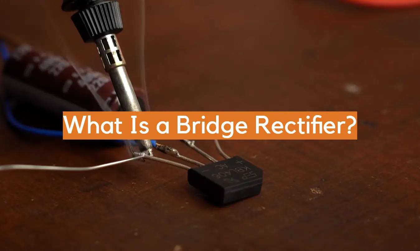
Do you know what a bridge rectifier is? Most people don’t, but if you’re working with electrical circuits, it’s important to have at least a basic understanding of these devices. To put it simply, bridge rectifiers are utilized to transform alternating current (AC) into direct current (DC). Read on to learn more about how they work and why they’re used.
What is a Bridge Rectifier?
By transforming alternating current (AC) to direct current (DC), a bridge rectifier enables electrical energy to be appropriately used and managed. This circuit comprises of four or more diodes arranged in a bridge configuration, ensuring optimal efficiency. When AC voltage is applied, the diode bridge rectifies the input, resulting in a unidirectional output. Bridge rectifiers are used in many consumer electronics and appliances, such as televisions and computers.
They can also be found in industrial applications such as pumps and motors. Bridge rectifiers offer several advantages over other types of rectifying circuits, including better efficiency and higher power ratings. Additionally, they require fewer components than other circuits, making them simpler to assemble and less expensive to manufacture. Part of the reason why bridge rectifiers are so popular is because they can easily be constructed using standard components like diodes. With the right parts and instructions, anyone can build a bridge rectifier circuit.
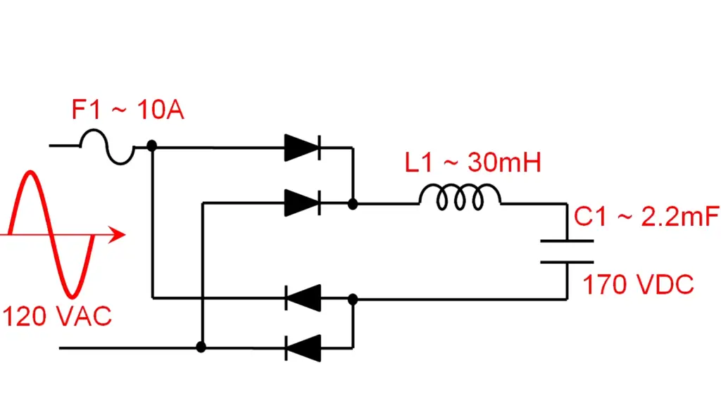
Overall, bridge rectifiers provide an effective and affordable way to convert AC voltage into DC voltage. They are useful in many different applications where conversion from AC to DC is required, such as in power supplies for consumer electronics or industrial equipment. As a result, bridge rectifiers remain a popular choice for engineers when it comes to designing electronic circuits. [1]
Construction
The bridge rectifier has two distinct inputs: one for each phase of an AC source. When the AC voltage alternates between positive and negative, it allows current to flow through each diode in alternating directions. This causes both positive and negative half cycles to be filtered out, creating a smooth DC output waveform. This also results in the DC output voltage being lower than the AC input voltage, due to the drop across each diode.
In order to minimize power loss, it is important to use a bridge rectifier with low resistance diodes and adequate heat sinking. The higher the quality of the components used in a bridge rectifier, the more efficient it will perform.
Bridge rectifiers are commonly found in many electronic circuit applications such as AC/DC adapters, motor controllers, battery chargers, and power supplies. It is also used for high-frequency switching operations since diodes have better switching characteristics compared to other components like transistors.
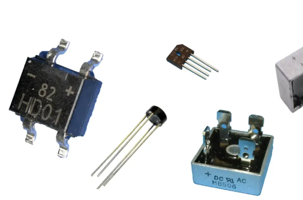
Working
This type of rectification is an efficient means to convert AC power into DC power and is used in applications such as charging batteries, motor speed control, supplying DC loads, and many others.
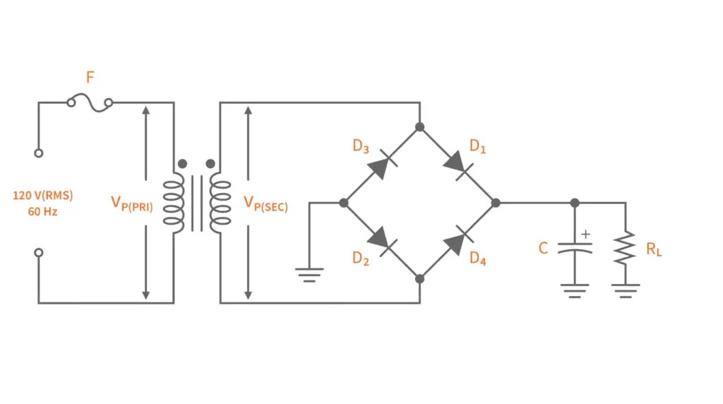
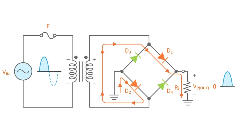
The basic mechanism behind the operation of a bridge rectifier involves connecting two opposite terminals of an AC source to two diode pairs connected together in a “bridge” configuration. When the input voltage is applied at the two ends of the bridge, current flows through two diodes while the other two remain reverse biased.
This creates a pulsating DC output waveform on one side of the bridge which can be smoothed out by a filter capacitor in order to get a constant DC output. The advantage of using this type of rectification is that it allows the control of both positive and negative voltage swings, which enables better utilization efficiency as compared to other topologies. [2]
Bridge Rectifier Circuit Diagram
A bridge rectifier circuit diagram consists of four diodes connected in a ‘bridge’ configuration, with two AC input terminals and two DC output terminals. The diodes are arranged so that the positive half cycle of the AC waveform is converted to a positive DC voltage across the load resistor, while the negative half cycle of the waveform is converted to an equal magnitude but opposite polarity DC voltage. This creates an output waveform which has all negative-going or all positive-going pulses, depending on the direction of current flow through the load resistor.
Types of Bridge Rectifiers
A bridge rectifier consists of four diodes in a full-wave circuit configuration that provides the same output polarity regardless of the input polarity. There are two main types of bridge rectifiers: center-tapped and non-center-tapped.
Center-tapped Bridge Rectifier: The center-tapped bridge rectifier is composed of two diode pairs arranged in a bridge formation around a common center point or tap. This type of rectifier works by converting both half cycles of an AC signal into DC current, with the positive half cycle being converted to one polarity and the negative half cycle being converted to the opposite polarity.
Non-Center Tapped Bridge Rectifier: In this type of bridge rectifier, two diode pairs are arranged in a bridge formation, but there is no common center point. This type of rectifier works by converting only one half cycle of the AC signal into DC current, with the positive half cycle being converted to one polarity and the negative half cycle being ignored.
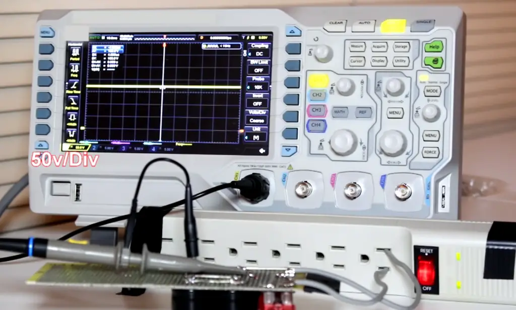
Each type of bridge rectifier has its own advantages and disadvantages. Generally speaking, non-center-tapped bridge rectifiers have fewer components and thus can be more efficient than center-tapped designs. However, they also produce a slightly lower output voltage compared to center-tapped designs. Additionally, non-center-tapped designs require more complex circuitry for full wave rectification compared to center-tapped designs. [3]
Bridge Rectifier Waveform
The waveform has two parts: positive and negative. During the positive part, electricity flows from the anode of one diode to the cathode of another diode. During the negative part, electricity flows in the opposite direction.
The result is a flat line with peaks at each end where the polarity changes from positive to negative or vice versa. This is also known as a full-wave rectified voltage. While this type of waveform does not have any sine waves like AC does, it still produces relatively clean DC power for use in most applications.
In addition to producing a bridge rectifier waveform, full-wave rectifiers can also contain diodes that are arranged in such a way that they function as voltage multipliers. For example, one type of diode called a “voltage doubler” is used to double the output voltage of the rectifier circuit. This is useful for applications that require higher voltages than what AC provides.
Characteristics of Bridge Rectifier
It consists of four diodes connected in the form of a bridge as shown in the diagram below.
The main characteristics of bridge rectifiers are:
- A bridge rectifier can handle large peak inverse voltage values and generate relatively low ripple factor compared to other types of full-wave rectifiers.
- It can also provide higher power efficiency than half-wave rectification due to its ability to use both positive and negative cycles of input AC waveform to produce DC output.
- Bridge rectifiers are easy to construct with the help of a limited number of parts, such as four diodes.
- They are suitable for both low and high voltage rectification applications.
- Further, they also offer better protection against overvoltage conditions compared to other types of full-wave rectifiers due to their ability to withstand large peak inverse voltages.
Bridge Rectifiers have numerous advantages and find use in many applications including power supplies, DC motor controllers and various other industrial electronics applications. It is important to note that these devices should be chosen carefully according to the requirements of the application and installed properly following safety standards applicable in your region. [3]
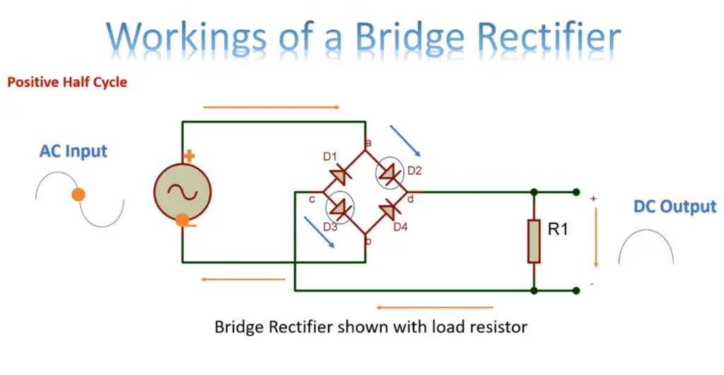
Advantages
A bridge rectifier has several advantages over other types of rectifiers. First, it is more efficient than a half-wave or full-wave rectifier because it allows for the transmission of both positive and negative cycles of alternating current (AC) to be converted into direct current (DC). This means that less energy is wasted by dissipating as heat during the conversion process.
Additionally, a bridge rectifier can also provide improved AC voltage regulation due to its ability to smooth out any fluctuations in the incoming AC signal. Furthermore, unlike some other types of rectifiers, bridge rectifiers are usually quite reliable and require minimal maintenance.
Finally, they tend to be much smaller in size than their counterparts which makes them easier to integrate into a variety of designs and applications.
As can be seen, bridge rectifiers have a wide range of advantages that make them a popular choice for use in many different electronic circuits and systems. As such, they can be found in everything from computers to power supplies, electrical appliances, and automotive systems.
Despite these advantages, however, it is important to remember that like all other types of rectifiers, bridge rectifiers also come with their own set of limitations which should be considered when making the decision to include one in your design. With this in mind, it may still prove to be a worthwhile investment for many projects!
Disadvantages
Bridge rectifiers are not ideal for all uses. Their biggest disadvantage is that the output voltage does not remain stable over time, but instead decreases with increasing input voltage. Additionally, bridge rectifiers require four diodes as opposed to a single diode in other rectifier designs, making them more expensive and complex than other types of rectifiers.
Finally, they generate substantial amounts of heat due to the power loss caused by their internal resistance and switching transients. Heat must be managed carefully to ensure that the components do not become damaged or malfunction. In some cases, additional cooling components may need to be added for proper operation.
Overall, bridge rectifier circuits are effective at converting AC electrical signals into DC ones, but they also present a number of disadvantages that must be taken into consideration. It is important to evaluate the pros and cons of bridge rectifiers before selecting them for a particular application. [4]
History of Bridge Rectifiers
The history of bridge rectifiers can be traced as far back as the 19th century. The first use of a bridge rectifier was documented in 1891, when Charles Proteus Steinmetz invented the four-layer structure for AC to DC conversion. This was initially used for powering streetcars and later proved to be an efficient way of converting alternating current (AC) into direct current (DC). Since then, the design has been refined and improved upon over time, leading to more reliable models with higher efficiency ratings.
Today, most modern electronics rely on bridge rectifiers to power their components or create stable voltage supplies. Bridge rectifiers are found everywhere from computer motherboards and electric vehicles to household appliances.
Bridge rectifiers are typically composed of four diodes arranged in a bridge configuration, which allows AC input to be rectified into DC output. This device can also be used as an inverter; by reversing the polarity of the current and voltage, it is possible to convert from DC input to AC output.
Full-Wave Bridge Rectifiers vs. Half-Wave Bridge Rectifiers
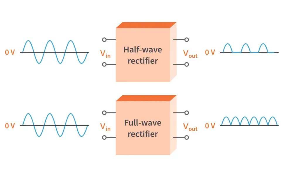
Bridge rectifiers are divided into two categories: full-wave and half-wave.
Full-wave bridge rectifiers are the most common type of bridge rectifier in use today, due to their superior efficiency compared to half-wave variants. In a full-wave bridge rectifier, both positive and negative cycles of an AC input signal are used, allowing for smoother DC output with fewer spikes than half-wave designs. The four diodes of a full wave bridge form two branches which approximate a sinusoidal voltage waveform across the load resistor connected between them.
Half-wave bridge rectifiers take only one-half cycle of an AC input signal, and can only be used in applications with a single-phase AC supply. This type of bridge rectifier is less efficient than full-wave designs, since it does not utilize both cycles of the AC input signal. Maximum power delivery to the load is also lower when compared to full wave bridge rectifiers. The output voltage from this type of circuit contains more ripples than the smooth DC output from a full wave design.
Regardless of which type you choose, bridge rectifiers are extremely popular power conversion circuits due to their ease of use and high efficiency ratings. When selecting a bridge rectifier for your application, think carefully about whether you need a half or full-wave design in order to get the best performance from your circuit. [5]
Applications of the Bridge Rectifier
The bridge rectifier is a widely used device, found in a variety of electronics applications. It is frequently used as an AC-to-DC power converter, to convert alternating current (AC) into direct current (DC). Bridge rectifiers are also used in DC motor speed controls and voltage doubler circuits. Additionally, they can be employed in switching power supplies and audio amplifiers.
The bridge rectifier’s ability to block reverse-current flow from the load makes it ideal for preventing damage or electrical shocks from occurring due to short circuits or other unexpected events.
Furthermore, its four diodes provide low cost protection against overvoltage surges. Therefore, bridge rectifiers are essential components in many types of electronic products and vehicles such as cars, boats, and aircraft.
The bridge rectifier’s simple construction also makes it a reliable and cost-effective device for many applications where higher power levels are not required. Finally, bridge rectifiers can handle relatively high peak currents. As a result, they are commonly used in AC motor controllers, battery chargers, and de-magnetizing systems.
In summary, the bridge rectifier is an important component in many types of electronics applications due to its low cost, durability, and ability to block reverse-current flow from the load. Its wide range of applications includes motor speed controls, voltage doublers circuits, switching power supplies and audio amplifiers as well as other consumer products such as cars and boats. [6]
FAQ
What is the purpose of a bridge rectifier?
It works by using four diodes arranged in a “bridge” configuration that allow the current to flow in only one direction. This type of circuit is commonly used in power supplies, appliance control circuits, and other applications which require DC voltage as an output.
What are the advantages of a bridge rectifier?
Bridge rectifiers offer several advantages over other types of rectifiers. They are simple and easy to construct with just four diodes, require minimal components, provide full-wave rectification, have low voltage drop across the diodes for efficiency, and operate at high frequencies. Additionally, they can be used for both low- and high-voltage applications.
What are the disadvantages of a bridge rectifier?
The main disadvantage of a bridge rectifier is its higher cost compared to other types of rectifiers. Additionally, it has lower efficiency at very low load currents due to the voltage drop across the diodes. Finally, it requires heatsinking in order to dissipate heat generated by the diodes when operating with large currents.
What is an example application where a bridge rectifier could be used?
A common application where a bridge rectifier can be used is in power supplies for electronic devices such as computers, printers, and TVs. In this type of setup, an AC supply from an external source is connected to the bridge rectifier, which then converts it to DC power suitable for powering the device.
How do I select a bridge rectifier for my application?
When selecting a bridge rectifier for an application, make sure to consider the current rating of the circuit and its maximum reverse voltage rating. Additionally, pay attention to other factors such as frequency, temperature range, terminal type, insulation class, and noise level. Finally, ensure that the selected bridge rectifier meets all safety standards applicable in your area.
How does a bridge rectifier convert AC to DC?
A bridge rectifier is an electronic circuit that converts alternating current (AC) to direct current (DC). It does this by using four diodes arranged in a bridge circuit. The AC voltage enters the bridge, and each diode only allows electricity to flow in one direction through it. This changes the AC voltage into unidirectional DC voltage, which can then be used for power applications such as motor control or charging batteries. By changing the frequency of the AC input signal, the output of a bridge rectifier can also be changed. This makes it an extremely versatile device for many different types of applications.
What is a bridge type rectifier diode?
A bridge type rectifier diode is a diode that can withstand higher voltages and currents than regular rectifier diodes. They are used in power supply circuits to help convert AC power into DC power. Bridge type rectifier diodes are typically rated for upwards of 600 volts, and often have reverse breakdown voltages of up to 1,000 volts. They also come in many different types, such as Schottky barrier, fast recovery, and ultra-fast recovery. Each type has its own advantages and disadvantages depending on the application it will be used for.
What are some common uses for bridge rectifiers?
Bridge rectifiers are used in a variety of applications from motor control to battery charging. In motor control applications, they can be used to convert AC signals into DC signals for motor control circuits. They are also commonly used in power supplies as a means of converting AC current into DC current for powering electrical equipment. In addition, bridge rectifiers can be used for charging batteries, as well as being employed in high voltage and low voltage systems. Lastly, they are often used to provide variable frequency or pulse width modulation (PWM) signals for various applications.
Does a bridge rectifier increase voltage?
No, a bridge rectifier does not increase voltage. It is used to convert AC current into DC current, and it may change the frequency of an AC signal or provide PWM signals, but it does not increase voltage. The output voltage of a bridge rectifier depends on the input voltage, so if you want to increase the output voltage you must first increase the input voltage.
What is the output voltage of a bridge rectifier?
The output voltage of a bridge rectifier depends on the input AC power source and the number of diodes used. Generally, two or four diodes are used in a traditional bridge rectifier configuration. When two diodes are used, the output voltage is approximately 1/2 of the input AC voltage. When four diodes are used, the output voltage is closer to the full input AC voltage. The addition of capacitors and other components can further increase this output voltage stability. In some cases, it may be possible for a bridge rectifier to provide an unregulated DC supply that is slightly higher than the peak value of its input AC supply.
What causes rectifier failure?
Rectifier failure can occur when the diodes become damaged due to excessive current, voltage, temperature, or age. Additionally, an inadequate heatsink may lead to the rectifier working at higher temperatures and cause premature failure. The use of incorrect components can also lead to rectifier failure. Lastly, improper wiring and connections can cause shorts which will result in a failed rectifier. It is important to ensure that all components are rated for their intended purpose as well as proper installation techniques used.
What is the importance of bridge rectifiers?
Bridge rectifiers play a vital role in many electrical systems and devices by converting AC power into DC power. As such, it provides a stable voltage supply allowing for more efficient system operation. Additionally, its ability to convert AC power into DC power makes it a great choice for applications that require a regulated voltage supply. Finally, bridge rectifiers help protect electrical devices against potential damage from spikes and surges in the power source.
Useful Video: Bridge Rectifier Animation
Conclusion
In conclusion, a bridge rectifier is an electronic component that allows current to flow in one direction only. It consists of four diodes connected in a ‘bridge’ configuration and can be used to convert AC voltage into DC voltage. The advantages of using a bridge rectifier include its ability to provide stable output voltages, low cost, easy installation, durability and high efficiency. However, it has some drawbacks such as high reverse leakage current and large losses caused by the internal power dissipation of the diodes. To avoid these issues, proper selection and sizing should be done before installing a bridge rectifier.
Ultimately, bridge rectifiers are essential components in many electronics applications and play an important role in ensuring safety and reliability.
References
- https://byjus.com/physics/bridge-rectifier/
- https://www.derf.com/how-a-bridge-rectifier-works-step-by-step-tutorial/
- https://www.elprocus.com/bridge-rectifier-circuit-theory-with-working-operation/
- https://www.analog.com/en/design-center/glossary/full-bridge-rectifier.html
- https://www.electrical4u.com/bridge-rectifiers/
- https://www.physics-and-radio-electronics.com/electronic-devices-and-circuits/rectifier/bridgerectifier.html










Leave a Reply