
In the world of electronics, there are many different types of amplifiers. One type is the non-inverting op-amp, which has several unique properties that make it useful in a variety of applications. In this blog post, we’ll take a closer look at what a non-inverting op-amp is, how it works, and some of the ways it can be used.
What Is A Non-Inverting Input?
An op-amp’s non-inverting input has a voltage gain of less than one, meaning it maintains the same polarity as its initial signal. When connected correctly, a non-inverting input will output an amplified version of the original signal. This type of amplifier is commonly used in applications such as active filters and audio amplifiers.
The main advantage of using a non-inverting input over other types of amplifier inputs is that it can provide greater gain with very little distortion or noise. Additionally, this type of amplifier can be made more stable by adjusting additional components like resistors and capacitors, which makes them suitable for use in high-frequency circuits where stability is critical. [1]
How Does Non-Inverting Op-Amp Work?
The non-inverting op-amp is designed with the presumption that one of its inputs (the non-inverting) will be operating at a higher voltage than the other input (the inverting). When this relationship holds true, the gain is determined by the ratio of resistors in the circuit.
Constructing a non-inverting op amp circuit is an uncomplicated task that only requires three components: an operational amplifier, two resistors and an input voltage source. The initial resistor, R1, is bridged between the positive input and earth; whereas the second resistor, R2, interlinks with the negative input and ground. Subsequently, the input voltage origin should be coupled with the non-inverting entrance of an operational amplifier.
When an input voltage is applied to this circuit, a current flows through each of the resistors. This current causes a voltage drop across each resistor which can be calculated based on Ohm’s law (V = I*R). Since these voltages differ depending on their respective resistances, they will cause an amplification or gain in the output voltage of the op amp. The gain is determined by the ratio of R1 divided by R2.
So if we have R1 set at 10kΩ and R2 set at 5kΩ, the gain of the circuit will be 2. By adjusting the values of R1 and R2, you can modify the gain of your non-inverting op amp circuit to whatever value you desire.
The simplicity of this circuit structure makes it one of the most preferred configurations when it comes to amplifying electrical signals, as it provides a high degree of accuracy and reliability in terms of output voltage level variations. Moreover, due to its low cost compared to other types of operational amplifiers, it is widely used in many everyday applications such as audio systems and scientific instruments. [2]
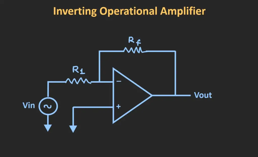
What Is The Difference Between An Inverting And Non-Inverting Amplifier?
The gain of this amplifier can be controlled by changing the resistor values in the feedback loop. On the other hand, a non-inverting op-amp amplifier is a circuit where the polarity of the output signal remains unchanged compared to the input signal. The gain of this amplifier can also be adjusted by changing resistor values in its feedback loop but with different constraints than an inverting amplifier. In addition, an offset voltage can also be applied to control both types of amplifiers without affecting their gains significantly.
Overall, depending on your application, you have to decide if you need an inverting or non-inverting amplifier, since both have different advantages and disadvantages. One major difference between the two is that an inverting amplifier has a negative gain while a non-inverting amplifier has a positive gain. This means that with an inverting amplifier, the output signal will be inverted from the input signal and with a non-inverting amplifier, the output signal will remain unchanged from the input signal. Other differences include power dissipation, bandwidth limitations, stability and noise immunity. [3]
Non-Inverting Op-Amp Voltage Gain
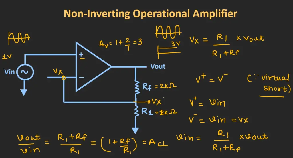
A non-inverting op-amp has a voltage gain of 1+(R2/R1). This means that for every one volt increase at the input, there is an equal and opposite change in output voltage. In most cases, this is ideal for amplifying the signal without introducing any distortion.
The voltage gain can be increased by increasing R2 or decreasing R1 to produce a greater differential between the two resistors. For example, if R1 = 10k ohms and R2 = 20k ohms then the voltage gain would be 3 (20/10+1). This means that for every three volts increase at the input, there will be nine volts of output. It’s important to remember that this only applies when using a non-inverting op-amp.
The voltage gain can also be decreased by decreasing R2 or increasing R1, however this may lead to distortion in the signal due to the increased impedance of the circuit. It is important to consider the desired voltage gain and make adjustments accordingly before connecting a non-inverting op amp.
In summary, a non-inverting op-amp has a voltage gain of 1+(R2/R1) which can be adjusted by changing the two resistors connected in series with each other. While this is an ideal way to amplify signals without introducing any distortion, it is important to keep in mind that excessively high gains may lead to undesired results. Adjusting the resistor values accordingly will ensure that the desired voltage gain is achieved. [4]
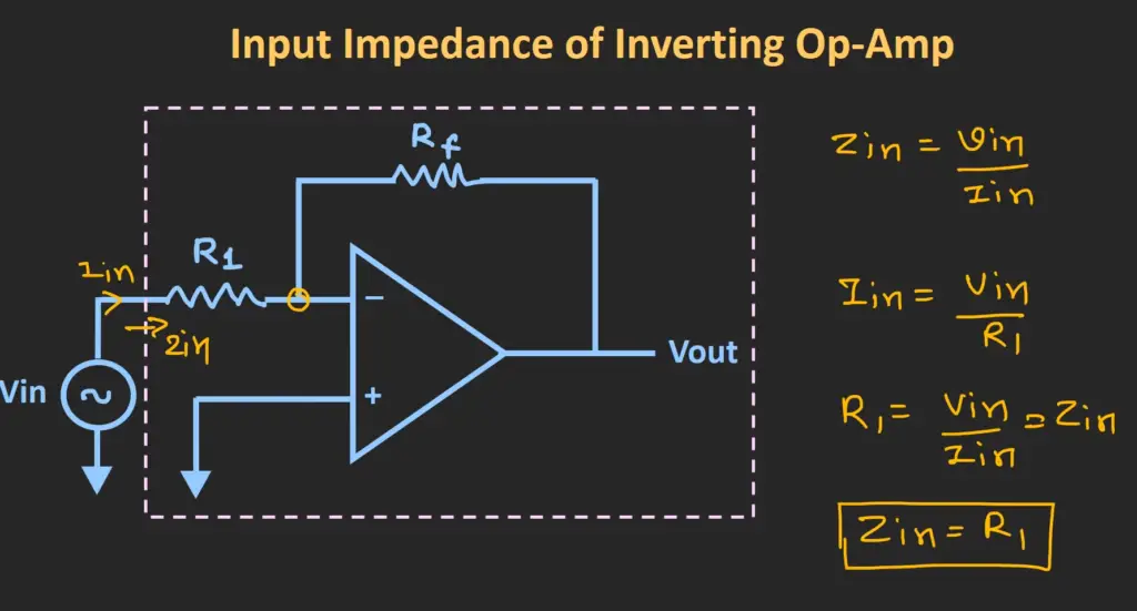
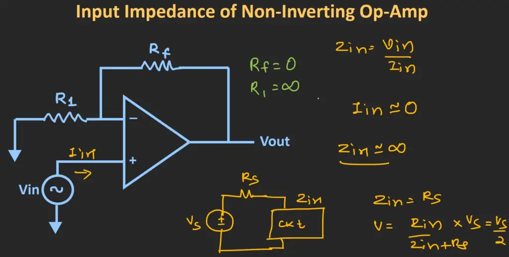
Input Impedance
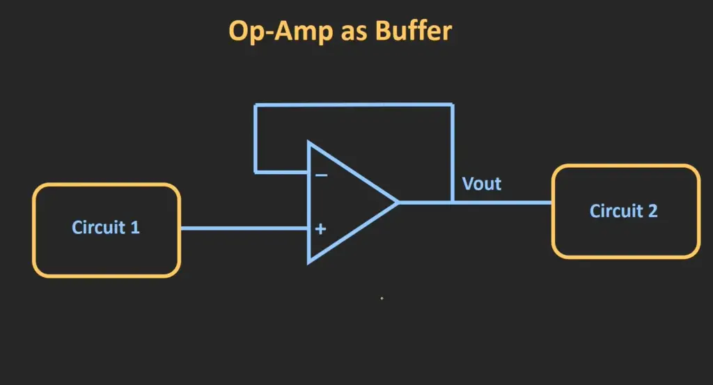
A non-inverting op-amp has an extremely high input impedance, which makes it very difficult for any current to enter the device. The output impedance of the op-amp is also very low, making it a useful buffer between circuits that have different impedances or voltages. A non-inverting op-amp is used in many applications such as amplifiers, filters, and integrators.
The input impedance of the non-inverting op-amp allows it to stay unaffected by changes in external loading conditions or by other circuit components. This feature helps to provide a wide range of frequency responses and gain settings while minimizing noise and distortion. Additionally, due to its higher input resistance, non-inverting op-amps are less susceptible to electrical noise. This makes them ideal for use in low-noise applications.
Overall, the high input impedance of a non-inverting op-amp is advantageous because it provides better signal transfer from one circuit to another and prevents any possible distortion or interference. It also helps to improve overall performance by producing more accurate results with higher fidelity. As a result, non-inverting op-amps are used broadly in many different types of circuits and systems.
Output Impedance
The output impedance of the non-inverting op-amp is very low, which is ideal for driving heavy loads. This allows the non-inverting op-amp to be used in many applications that require high current draw. At the same time, it helps reduce power losses due to voltage drop across a load.
The output impedance can also be easily adjusted by changing certain external components such as resistors or capacitors connected to the circuit. Because of this versatility and ease of adjustment, it is often used in applications that require precise control over signals and maximum efficiency with minimal power consumption.
Additionally, because of its low output impedance, there are generally very little signal distortions caused by the non-inverting op-amp regardless of load conditions. This makes the non-inverting op-amp ideal for applications that require clean, accurate signals.
Overall, the low output impedance of the non-inverting op-amp is one of its key advantages compared to other types of amplifiers, and it greatly expands the range of applications where this amplifier can be used. It also ensures high efficiency and minimal power losses in many applications.
Non Inverting Op Amp Waveform
It is a type of feedback amplifying device in which the output voltage is proportional to the difference between the input and feedback signals. The gain of this circuit can be controlled by varying the ratio of two resistors, R1 and R2.
The non-inverting op amp waveform has two main components: an input voltage (Vi) and a feedback voltage (Vf). When Vi is greater than Vf, then the output voltage will increase proportionally according to the formula: Vo = A(Vi – Vf), where A is the gain of the amplifier determined by the resistor values.
The non-inverting op amp waveform can be used for a variety of applications, including voltage gain, current amplifying, filtering, signal processing and more. This type of amplifier is ideal for low-power applications due to its high gain and low power consumption.
In addition to being versatile and efficient, the non inverting op amp waveform is also relatively easy to construct. The circuit consists of only two transistors (or three if an output buffer is included), making it simple enough to fit in small packages and use in portable devices.
Overall, the non inverting op amp waveform offers great flexibility and efficiency for low-power applications. Its versatility makes it suitable for a wide range of uses, from signal amplification and processing to voltage and current gain. As such, the non inverting op amp waveform continues to be a popular choice for many electrical circuits. [5]
Non-Inverting Op-Amp Solved Problems
Non-inverting op-amp circuits are used in many applications, such as signal conditioning, filtering, and gain control. In order to ensure proper operation of these circuits, it is necessary to solve for the circuit parameters. This can be done by deriving equations for the gain and input resistance of the amplifier.
Once these equations have been derived, a number of solved problems can be used to demonstrate how to use them. These include determining the input impedance at each node of a non-inverting amplifier circuit, calculating the voltage gain and current gain based on given resistor values, finding the output current when given an input voltage, and calculating the cutoff frequency of a filter using a non-inverting op amp.
These examples illustrate the importance of understanding non-inverting op-amp circuits and their equations in order to get the best performance out of them. Additionally, by solving problems related to these circuits it is possible to become more familiar with their behavior and gain a better understanding of how they work.
In conclusion, non-inverting op amps are versatile and efficient amplifying devices that can be used for a variety of applications. By deriving the appropriate equations and solving problems related to them, designers can get a better idea of how to use this type of amplifier in various applications. Doing so will ensure that the circuit performs optimally and provides the desired results.
Non-Inverting Op-Amp With Two Voltage Sources
It uses an operational amplifier (op-amp) to add or subtract the two input voltages together in order to achieve the desired output voltage. The circuit consists of resistors, capacitors, and an operational amplifier connected in a specific configuration.
The output voltage is determined by the ratio of the resistor inputs, which will vary depending on the gain set for the op-amp. This type of configuration is often used for audio applications as it allows for amplification or attenuation of sound signals. Additionally, this type of op-amp can be used to provide adjustable level shifts between circuits with different DC operating voltages.
The non-inverting op-amp with two voltage source circuits is also used to provide gains of greater than one, as well as providing a way to isolate two circuits from each other. It can be used in instrumentation amplifiers and active filters, as it provides high input impedance while still maintaining low output impedance. This type of configuration is also commonly used in analog computers and signal conditioning applications.
Overall, the non-inverting op-amp with two voltage sources provides flexibility and accuracy when it comes to combining multiple signals together. With its wide range of applications, it is an invaluable tool for engineers who need to manipulate or amplify a signal quickly and efficiently. It also allows for quick adjustment of gain settings, allowing for further customization of audio or other signals. This versatile configuration is an important tool in many electronics applications.
Advantages
A non-inverting op amp has a number of advantages over an inverting op amp configuration. One advantage is that the circuit gain can be controlled by simply changing the values of two resistors, while in an inverting amplifier configuration, it would require several components to do this. This makes the non-inverting configuration simpler and cheaper to construct.
Additionally, the output voltage of a non-inverting amplifier is not inverted compared to its input unlike in an inverting amplifier where it is 180° out of phase with its input. This may simplify connection to other parts of a system requiring signal inputs as they will not have to be configured for inverse signals.
Lastly, because no feedback loop is present in a non-inverting amplifier design, the overall gain of the circuit is significantly higher than with an inverting amplifier. This makes it ideal for circuits requiring a high level of amplification.
In conclusion, non-inverting op amps provide several advantages over their inverting counterparts: they are simpler and cheaper to construct, they produce output that is not inverted from the input signal, and have a much higher overall gain than inverting amplifiers. All of these features make non-inverting op amps a highly desirable choice for many applications. [6]
Disadvantages
Non-inverting amplifiers have some inherent disadvantages. Most notably, the gain of these circuits can be limited by bandwidth, slew rate and noise.
Additionally, due to the presence of feedback in non-inverting configurations, settling time (the time it takes for a signal to stabilize after a change in input) may also be increased.
Finally, the voltage gain can vary significantly with changes in temperature or supply voltage, making it necessary to employ additional components such as temperature compensators or regulators. Despite these drawbacks, non-inverting amplifier circuits are often used because they provide a simple and efficient way to increase an input signal’s amplitude without introducing distortion.
Where Are Non-Inverting Op Amps Used?
Non-inverting op amps are commonly used in active filters, signal amplifiers and integrators. The non-inverting configuration enables a higher gain than the inverting op amp configuration, as well as lower distortion levels. They can be used to boost weak signals to generate stronger outputs, such as a microphone preamp or an antenna amplifier. They can also be used for audio processing applications such as tone and volume control.
In addition, they can be employed in motor speed controllers, temperature controllers and analog to digital converters. All these applications require precise and reliable voltage amplification with variable gains. Non-inverting op amps provide an ideal solution due to their versatility and accuracy.
The most common non-inverting op amp configurations are the differential amplifier, summing amplifier, and voltage follower. In each of these cases, the non-inverting input terminal is higher than the inverting input terminal so that the output signal is inverted in respect to its input. This makes them ideal for various applications where a precise amplified output is required. [7]
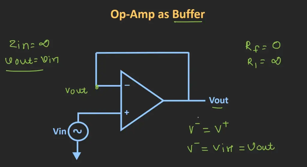
Single Supply Non-Inverting Amplifier
The output voltage is in phase with the input voltage, meaning that the polarity of both signals are the same. This kind of amplifier can operate on a single power supply and therefore it doesn’t require two separate power supplies to function properly. It has an active component, usually an operational amplifier (op-amp), which performs linear amplification of the input signal or nonlinear processing such as compression, limiting, distortion and other effects.
This type of amplifier offers significant advantages over conventional amplifiers as it requires fewer external components for operation and typically provides good accuracy and stability. The single supply non-inverting op-amp is also useful for applications such as voltage buffering, active filters and noise reduction. It can be used in a wide range of audio applications such as guitar amplifiers, studio recording equipment and hi-fi systems.
FAQ
What does a non-inverting op-amp do?
Non-inverting op-amps are commonly used to increase signal gain, improve signal linearity, and provide a buffer between devices for impedance matching. Additionally, they can be used to construct different types of analog circuits such as active filters and integrators.
How does a non-inverting op amp work?
A non-inverting op amp works by converting an input voltage at one of its two inputs into an output voltage across its output terminals. The amount of amplification is determined by the ratio of resistors R1 and R2 connected to the non-inverting and inverting inputs, respectively. The output voltage is equal to (1 + R2/R1) × Vin, where Vin is the input voltage. What are the benefits of using a non-inverting op amp? Using a non-inverting op amp provides several benefits over other circuit configurations. Non-inverting amplifiers offer higher gain than inverting amplifiers, better noise immunity compared to single transistor amplifier circuits, increased linearity due to feedback stabilization, and they can be used as an impedance matching buffer between devices. Additionally, the configuration of a non-inverting op amp makes it easier to design complex analog circuits such as active filters and integrators.
Are there any drawbacks to using a non-inverting op amp?
The main drawback of using a non-inverting op amp is that it typically requires precise gain and offset adjustments to function properly. This means that the resistors R1 and R2 must be carefully chosen and adjusted to achieve the desired gain and offset voltage. Additionally, since the input signal is amplified without being inverted, any DC offsets in the input will be retained in the output signal, which can cause problems with some applications. Finally, non-inverting op amps are not as power efficient as other types of amplifiers such as complimentary emitter follower configurations.
Useful Video: Operational Amplifier: Non-Inverting Op-Amp and Op-Amp as Buffer (Op-Amp as Voltage Follower)
Conclusion
In conclusion, non-inverting op-amps are incredibly useful and versatile components that can be used to create a variety of different circuits. They have the ability to amplify voltage signals, filter out unwanted noise, and produce logic level outputs. Non-inverting op-amps are also relatively simple to understand and use in comparison to other types of amplifiers and they offer significant advantages when it comes to cost efficiency and overall performance. For these reasons, non-inverting op-amps remain a popular choice for many electronics applications today. Additionally, due to their wide range of uses, it is likely that non-inverting op-amps will continue to play an important role in future circuit designs. With this in mind, understanding how non-inverting op-amps work and how they can be used to create high quality circuits is essential for any aspiring electronics engineer.
References
- https://www.analog.com/en/design-center/glossary/non-inverting-op-amp.html
- https://www.electronics-tutorials.ws/opamp/opamp_3.html
- https://www.elprocus.com/non-inverting-op-amp/
- https://www.electronicshub.org/non-inverting-operational-amplifiers/
- https://www.electronics-notes.com/articles/analogue_circuits/operational-amplifier-op-amp/non-inverting-amplifier.php
- https://www.electrical4u.com/non-inverting-amplifier/