Logic circuits are a type of electrical circuit which uses one or more logic gates to process and store information. Logic circuits are commonly used in computers, communication systems, industrial automation systems, electronic toys, and many other applications. The most basic components of a logic circuit are the logic gates themselves. Each gate consists of one or more circles connected by lines. These circles represent the logic inputs and outputs of the gate.
In this article, we’ll explore what do these circles mean in a logic circuit, as well as some tips on how to read them. Let’s get started!
What is a circle with an x in a circuit diagram?
For example, if a regular AND gate has both inputs set to 1, its output is 1; however, if it’s an inverted AND gate, the output is 0. This can be useful for creating complex logic circuits with multiple inputs and outputs. [1]
What is the symbol of the incandescent bulb?
The incandescent bulb is represented by a circle with an arrow pointing away from it. This symbol is universally accepted in electronic logic circuit diagrams and means “Power” or “On”. The arrow indicates the direction of flow of electricity, usually indicated as positive (+) to negative (-). [1]
Do all light bulbs use the same symbol?
No, different types of light bulbs use different symbols. Incandescent lamps use a round circle with a radius line and halogen lamps use an ellipse with a long horizontal line inside. Fluorescent and LED lights will typically have an arrow or triangle symbol to represent their unique designs. Additionally, some circuits may not include a symbol at all for the light bulb. The symbol used to represent a light bulb will depend on the power source being used in the circuit and the type of lighting device being used. [1]
Why is it important to represent components with symbols?
In the world of digital electronics, components are represented with symbols in order to make schematic diagrams easier to read. Symbols allow for a standard representation of a device that can be understood by anyone who reads it. It also makes it simpler to identify what component is being used and how it is connected to other components.
For example, when you see an “AND” gate symbol, you immediately know that this component is a logic gate which will take two inputs and produce one output. Without the symbols, it would be difficult to decipher what components are being used and how they interact with each other without spending time looking up datasheets or long descriptions of what each component does. [1]
What does a circle with a line through it mean in electrical?
A circle with a line through it in electrical diagram is usually referred to as an “open circuit” symbol. It’s used to indicate that there is no connection between two points. This means that the current cannot flow from one point to another and thus, no power will be delivered to any of the points connected by this symbol.
It can also represent a switch that is open and not allowing current to flow through it. This type of open circuit symbol is commonly used in logic circuits, where the flow of electricity needs to be interrupted for the correct operation of the overall system. [1]
Which is off I or O?
The I and O symbols stand for input (I) and output (O). The inputs are the signals that enter the logic circuit, while the outputs are the signals that come out of it. In other words, the I is what you put into a logic circuit, and the O is what you get out of it. [1]
What are the symbols for power used on a wiring diagram?
When wiring a logic circuit, it’s important to know the symbols used when representing power. The two main symbols are usually a triangle or an inverted triangle.
A triangle is typically used to represent the Positive/Voltage (+) side of the power supply, and an inverted triangle is used for the Negative/Ground (-) side of the power supply. This is the same for both AC and DC power supplies.
In addition to these primary symbols, you may also find a circle used in connection with the triangle and inverted triangle symbols. This circle means ‘Power Switch’. It is usually drawn near the beginning of a circuit diagram where it can be seen clearly. The switch will allow you to turn off the power, thereby preventing any current from flowing through the circuit. [1]
What is a conductor symbol?
A conductor symbol is a part of a logic circuit diagram. It typically appears as a small circle, and it’s used to connect two components together or to create an output from an input. A good way to think about the conductor symbol is like a wire in traditional electrical engineering diagrams. In fact, the conductor symbol can be thought of as representing either a wire or an electrical connection. [1]
What are the 6 most common symbols used for an electrical schematic diagram?
The six most common symbols used in an electrical schematic diagram are circles, rectangles, diamonds, triangles, parallelograms and stars. Each of these shapes usually represent a particular device or component such as a transistor, resistor, capacitor or switch. The circle symbol is the most commonly used for devices such as transistors and switches which have multiple connections (such as a source, drain and gate). Rectangles usually represent resistors, diamonds usually represent diodes, triangles usually represent capacitors and parallelograms (or squares) often stand for integrated circuits. The star symbol is commonly used to indicate an earth ground connection in the circuit. [1]
What does the circle mean in a circuit?
The circle is the most commonly used symbol in a logic circuit, representing a logic gate. In its simplest form, the circle consists of two inputs and one output. It’s used to express various logical operations such as AND, OR, NOT, XOR, NAND, NOR and XNOR.
For example, an AND gate has two inputs, and the output is 1 only if both inputs are 1. The circle in the logic circuit represents this simple operation.
The circles can also represent more complex logical operations such as multiplexers or decoders. In these cases, the circle may contain additional lines representing other input pins or control signals. [1]
What is the arrow symbol in a circuit?
The arrow symbol in a circuit typically indicates the direction of flow and can help you understand how the logic works. It is often used to represent a signal or voltage, with its direction indicating whether it is increasing or decreasing. The arrow can also be used to indicate a clock pulse (a periodic current that oscillates from high to low). [1]
What are the three most common symbols found on a blueprint?
One of the most common symbols found on a blueprint is a circle. This symbol is used to indicate a logic circuit, which is an electronic system designed to perform logic operations. It usually consists of multiple components and can be broken down into three main categories: input, output, and control lines.
The circles in each category are represented by different symbols — a square for the input, an arrow pointing to the output, and a triangle pointing towards the control. This is why it’s important to know what each symbol represents on the logic circuit diagram before attempting to troubleshoot any problems. [1]
What are the symbols for switches in and around the home?
Switches are used to control the flow of electricity in and around the home, so it makes sense that each switch has its own symbol. In logic circuits, you’ll often find circles with either one or two lines coming off them; these are usually referred to as “switches” for simplicity.
The symbols represent single-pole switches (SPST) and double-pole switches (DPST).
Does the US use different symbols for wiring diagrams?
Yes, the US does use different symbols for wiring diagrams. Specifically, circuit diagrams in the US use circles to represent logic gates and rectangular boxes to represent switches, relays, and other components. This distinction can help make it easier to understand how a particular circuit works. Additionally, many of these symbols are standardized so that they are easily recognizable among engineers and electricians. However, it’s important to note that different countries may use different symbols to represent the same components. Therefore, it’s important to take special care when dealing with international wiring diagrams. [1]
FAQ
What are the circles in logic gates?
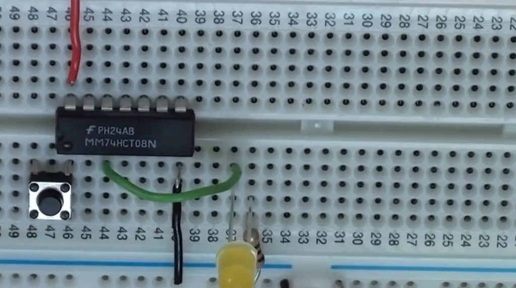
The circles in logic gates are called inputs. These inputs represent the conditions that must be met by the signals entering a gate in order for it to perform its intended function. Logic circuits are made up of different types of gates, including AND, OR, NAND, and NOR gates. Each type of gate typically has two or more inputs, each represented by a circle.
What is the circle before a logic gate?
The circle before a logic gate is called an input. It represents the conditions that must be met by the signal entering the gate for it to perform its intended function. The input signals can be either high (1) or low (0). When both inputs of a logic gate are high, the output will usually be high as well, while if one or both of the inputs are low, the output will usually be low. For example, in an AND gate, both inputs must be high for the output to be high; if one or both of the inputs is low, then the output will also be low.
What is the circle before the NOT gate?
The circle before the NOT gate is called an input. It is used to invert the signal entering the gate, meaning that a high (1) input will result in a low (0) output, and vice versa. The NOT gate is often used to create logic signals from other logic signals – for example, it can be used to create an ‘enable’ signal from an ‘active’ signal, or to invert a clock signal. It is also used for other logic operations such as setting flags and performing data comparisons.
What does the circle after a gate mean?
The circle after a gate is called an output. This is the signal that is produced by the logic gate, based on the input signals and operation of the gate. For example, in an AND gate, both inputs must be high for the output to be high; if one or both of the inputs is low, then the output will also be low. Similarly, in an OR gate, if either one or both of the inputs is high, then the output will be high. The output will usually be low if both inputs are low.
What does the circle at the end of the gate indicate?
The circle at the end of the gate is called an output. This is the signal that is produced by the logic gate, based on the input signals and operation of the gate. The output will usually be either high (1) or low (0), depending on what type of logic gate it is. For example, in an AND gate, both inputs must be high for the output to be high; if one or both of the inputs is low, then the output will also be low. Similarly, in an OR gate, if either one or both of the inputs is high, then the output will be high. The output will usually be low if both inputs are low.
What is the logic symbol for NOT gate?
The logic symbol for NOT gate is a circle with a line through it. This symbol represents the inversion of the input signal, meaning that a high (1) input will result in a low (0) output, and vice versa. The NOT gate is typically used to create logic signals from other logic signals – for example, it can be used to create an ‘enable’ signal from an ‘active’ signal, or to invert a clock signal. It is also used for other logic operations such as setting flags and performing data comparisons.
What are the symbols for logic gates?
The symbols for the different types of logic gates are as follows: AND gate (a triangle with two inputs and one output), OR gate (a circle with two inputs and one output), NAND gate (a triangle with two inputs and a line in an arc above it, representing the inverted output), NOR gate (circle with two inputs and a line in an arc above it, representing the inverted output), and NOT gate (circle with a line through it). All of these symbols are used to represent the function that each type of logic gate performs.
What is the not symbol in digital logic?
The not symbol in digital logic is a circle with a line through it. This symbol represents the inversion of the input signal, meaning that a high (1) input will result in a low (0) output, and vice versa. The NOT gate is typically used to create logic signals from other logic signals – for example, it can be used to create an ‘enable’ signal from an ‘active’ signal, or to invert a clock signal. It is also used for other logic operations such as setting flags and performing data comparisons.
The circles in logic gates are important parts of any digital circuitry and understanding what each one represents can help you create complex circuits that work the way you want them to.
Useful Video: Logic Gates | Visual Learners
Conclusion
In conclusion, understanding what the circles in logic circuits mean is important for developing an understanding of how logic gates and other components work together. Circles are used to represent inputs and outputs of logic gates. Knowing this can help you more easily solve problems related to circuit design and troubleshooting. Furthermore, it’s essential to understand the various types of logic circuits (AND, OR, NOR, XOR) and how the circles are used to represent each type. With this knowledge, you’ll be able to design your own circuits with confidence. Good luck!
References
- https://1stelectricians.co.uk/blog/what-is-a-circle-with-an-x-in-a-circuit-diagram/






Leave a Reply