SMD is an acronym that stands for Surface Mount Device. It refers to the type of electronic component that is mounted on the surface of a printed circuit board.
SMDs are typically much smaller than traditional components, which allows for more components to be packed into a given area.
They are also easier to solder, which makes them popular in modern electronics [1].
While SMDs have many advantages, they can also be more difficult to work with than traditional components.
This is because it can be difficult to identify the polarity of an SMD component and because they are often very small and close together on a circuit board. For these reasons, it is important to have a good understanding of SMD technology before attempting to work with it.
In the following blog post, our electronics experts will discuss the history and applications of SMDs!
What Is A Surface Mount Device Or SMD?
A surface-mount device (SMD) is a type of electronic device that has its components applied or seated on the surface of a printed circuit board (PCB).
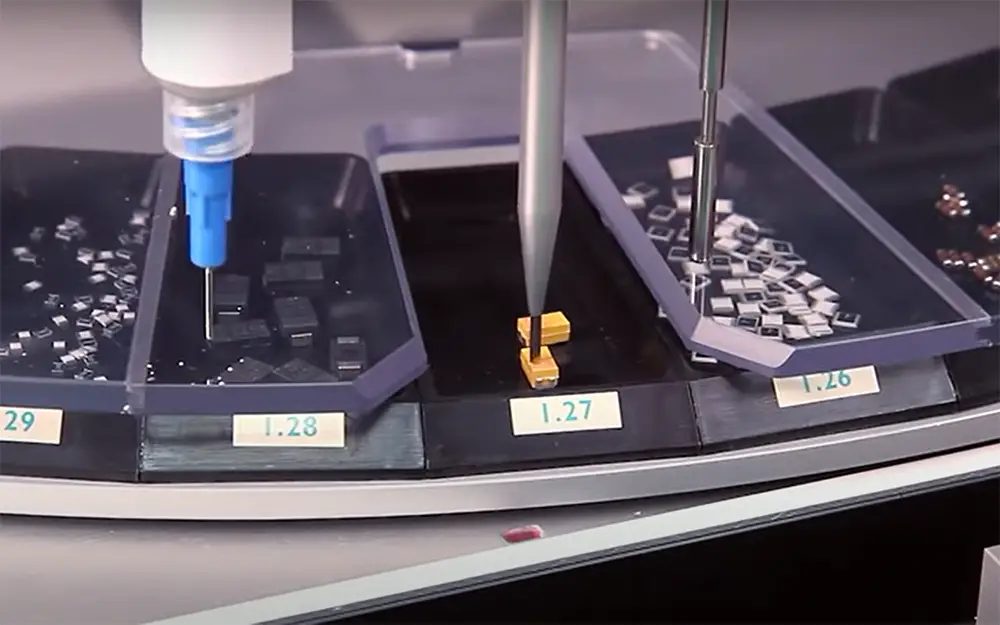
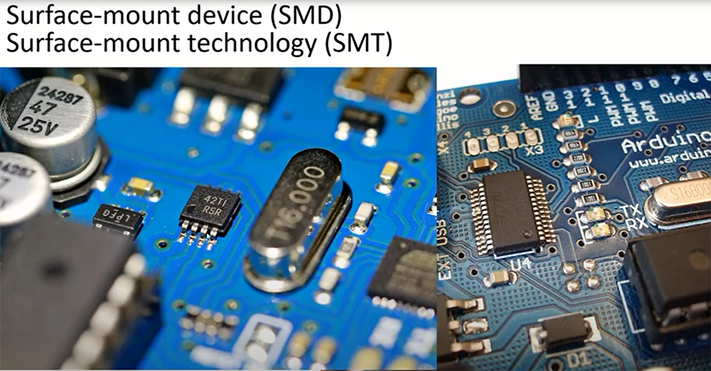
Surface-mount technology (SMT), which has largely replaced through-hole technology (THT), especially in devices that need to be tiny or flat, is based on this process of manufacturing electronic circuit boards.
When compared to the previous, SMT allows both sides of a PCB to be utilized as needed. This saves space and makes the board more flexible in design [2].
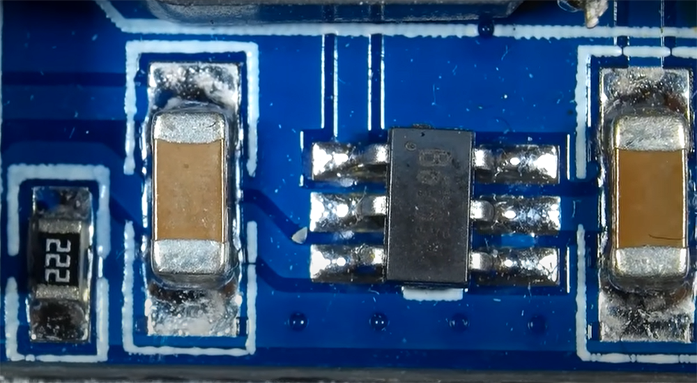
In an SMD, the leads or terminals are on the same side of the device as the body. The leads are usually much shorter than those found in devices using THT so that they can be seated closer to the PCB surface. This allows for a denser packing of components on a circuit board, which is often necessary for smaller electronic devices such as cell phones and computers.
The first thing you’ll notice about an SMD is that there are no legs protruding from its body as there would be with a through-hole component. Instead, pads or lands on the PCB correspond to where connections will be made with this type of device. In order to make a connection, the leads on an SMD are soldered directly to these pads.
SMDs can be classified into various types based on their size and function. The most common type is the leaded chip carrier (LCC), which has leads that extend from all four sides of its body. These leads are used to connect an LCC to a PCB. Other types of SMDs include ball grid array (BGA) devices, quad flat packages (QFPs), and plastic leaded chip carriers (PLCCs) [3].
Advantages:
- They are smaller in size as compared to through-hole components, which makes them more suitable for use in compact electronic devices;
- They can be placed on both sides of the PCB, which allows for greater flexibility in design;
- SMDs can be packed more densely on a circuit board than THTs, which is often necessary for today’s miniaturized electronic devices;
- They are less likely to come loose from the PCB since they are soldered directly to it;
- SMDs are less expensive to manufacture than THTs because they do not require drilling holes in the PCB;
Disadvantages:
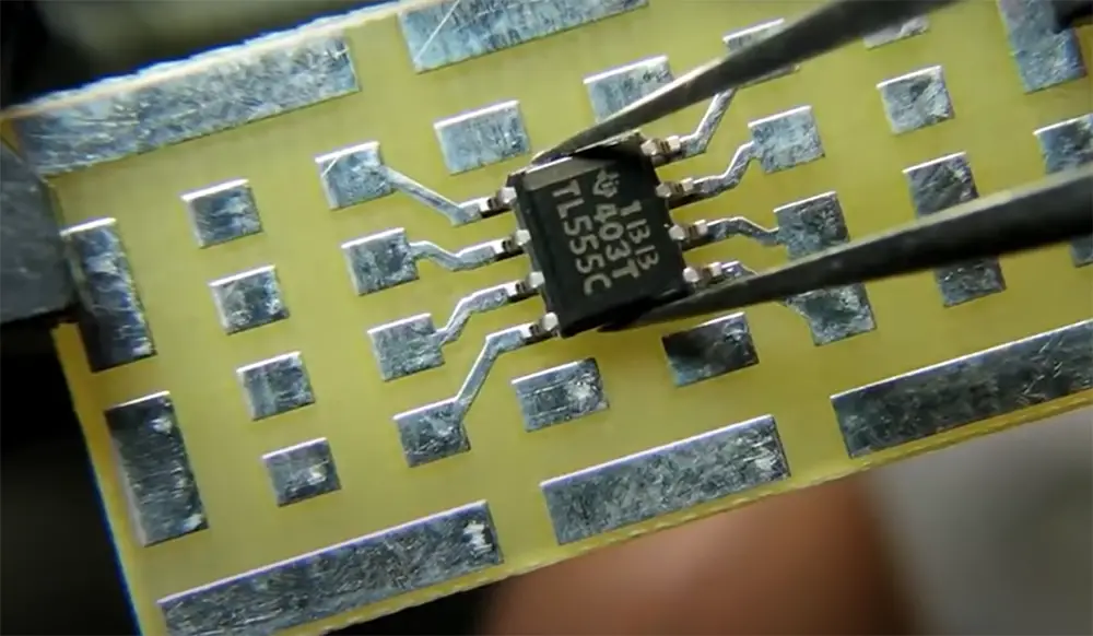
- They are more difficult to solder than THTs because of their small size and the fact that they are soldered directly to the PCB;
- They require special equipment for assembly and inspection, which adds to the cost of manufacturing;
- SMDs are not suitable for use in high-temperature or high-voltage applications;
SMT Meaning In Electronics
Surface mount technology (SMT) is a method for producing electronic circuits in which the components are mounted or placed directly onto the surface of printed circuit boards (PCBs). SMT has largely replaced through-hole technology (THT), which was the previous standard method for assembling electronic circuits.
Advantages:
- Increased production rates. Surface mount technology (SMT) equipment is generally faster than through-hole assembly equipment. This means that more products can be produced in the same amount of time, increasing production rates;
- Reduced assembly costs. SMT also usually requires less labor to assemble than through-hole components. This is because SMT components are typically smaller and require less time to place on the board. In addition, surface mount boards often have fewer holes than through-hole boards, which reduces the cost of drilling;
Disadvantages:
- Not all components are available in surface-mount packages. While most components can be purchased in a surface-mount package, some are only available in a through-hole package. This can make it difficult to find a replacement for a damaged component;
- Rework is more difficult. If a mistake is made during the assembly process, it can be difficult to remove and replace surface mount components. This is because the components are often very small and delicate. Through-hole components are easier to remove and replace if necessary;
What Is Through Hole Technology?
Through-hole technology (also known as “thru-hole”) refers to the method of mounting electronic components that employ leads inserted into drilled holes in printed circuit boards (PCB) and soldered to pads on the opposing side, either by hand placement or with automated insertion mount machines [5].
This technology is used in the manufacture of more than 90% of electronic products.
In contrast, surface-mount technology (SMT) refers to the method of mounting electronic components on the surface of a printed circuit board (PCB).
SMT does not require drilled holes; instead, leads are soldered directly to pads on the PCB.
This method is used in the manufacture of nearly all modern electronic products.
Advantages of THT:
- Can be used with through-hole and surface-mount components;
- Can be more easily repaired than SMT;
- Is less expensive for low volumes;
Disadvantages:
- More time-consuming to assemble;
- Higher assembly costs for high volumes;
- Prone to damage during handling;
Should Connectors Be SMD/SMT Or Through Hole Technology?
Capacitors that are inserted through holes have two key advantages over SMDs: increased temperature resistance and improved resistance to mechanical strain. The chip capacitor is less harmed by twists and/or vibrations on the PCB, which prevents failures and other faults [6].
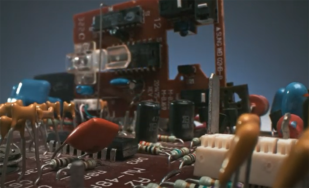
However, if cost is a major concern, SMD capacitors may be the way to go. Whichever type of capacitor you choose, make sure you select the right size and voltage rating for your application.
FAQ:
What is SMD used for?
Temperature sensors with SMD (surface mount device) components are the answer for applications where a sensor must be integrated onto a printed circuit board. The SMD construction technique makes it possible to create very small, lightweight temperature sensors.
There are many different types of SMD components, but the most common are resistors, capacitors, and inductors. These components are often used in digital circuits, such as cell phones and computers. SMD components can also be used in analog circuits, such as audio amplifiers.
SMD components are usually much smaller than through-hole components. This makes them ideal for use in compact electronic devices. SMD components can also be mounted on both sides of a printed circuit board, which saves space.
What is PCB?
PCB stands for a printed circuit board. A PCB is a board that connects all the components of an electronic device. It is made of a thin sheet of material called copper clad. The copper is etched to create the circuit traces.
There are two main types of PCBs:
- Single-sided PCBs have all their components on one side of the board;
- Double-sided PCBs have components on both sides of the board [7];
What are SMD components?
Surface-mounted devices (SMD) are electronic components that are mounted or placed directly onto the surface of a printed circuit board (PCB). SMDs have many advantages over through-hole components, including smaller size, lighter weight, and cheaper assembly costs.
However, because SMDs cannot be easily inspected or repaired once they are soldered onto a PCB, it is important to choose the right SMD for your application.
There are two main types of SMDs: passive and active.
Passive SMDs include resistors and capacitors, while active SMDs include transistors and integrated circuits (ICs).
To find the right SMD for your application, you will need to know the size, lead count, and pitch of the component. The size is the width and height of the component, in millimeters. The lead count is the number of leads or pins that connect the component to the PCB. The pitch is the distance between two adjacent leads, in millimeters.
You will also need to know the package type of the SMD. The most common package types are TO-92, SOT-23, and SOIC. TO-92 packages are used for small transistors and diodes, while SOT-23 packages are used for small ICs. SOIC packages are used for larger ICs.
Finally, you will need to know the voltage and power rating of the SMD. The voltage rating is the maximum voltage that the component can withstand without being damaged. The power rating is the maximum power that the component can dissipate without being damaged [8].
What is the difference between SMD and integrated circuit mounting?
Any electronic component soldered to only one side of a circuit board may be referred to as an SMD. The contacts on an SMD are most often made of metal “buttons” or flat metal prongs sticking out from the device’s edges or ends. A surface-mounted device can also be a type of integrated circuit.
An integrated circuit is a single, self-contained piece of circuitry. Because the package resembles a chip of plastic or ceramic, ICs are frequently referred to as “chips” [9].
How do I know what SMD components I have?
The first step is to identify the package and note how many pins it has. The package pins are sometimes located beneath the component or extended away from it. Also, get the dimensions of the part and compare them to a chart – once you’ve noted all this information, write it down for later use.
Check to see if the labeling on your board matches its size. Also, when measuring pin pitches (distance between pins), be careful that they aren’t mislabeled. It’s difficult to distinguish between a 1mm pitch and a 1.25mm pitch, for example. Make sure the measurement is correct; alternatively, divide the number of pins by the total number of pins to get the pin pitch.
The dimensions of a package are established in accordance with IPC-7351 or may be discovered by searching for the package type on Google and comparing measurements.
Package size can also be found on manufacturers’ websites via datasheets (or sometimes separate files from datasheets, which might take some digging around to discover).
Determine any markings on the component’s top. These can include a logo, a part number, or another identifier. Search for the markings online to find out more about the device [10].
What is an SMD fuse?
An SMD fuse is a type of electronic component that is used to protect circuits from overcurrent and short circuits. Fuses are made up of a thin strip of metal that melts when too much current flows through it. This interrupts the flow of current and prevents damage to the circuit.
SMD fuses are often used in automotive applications because they can be easily mounted on circuit boards. They are also available in a variety of sizes to accommodate different loads.
What is an SMD switch?
An SMD switch is a type of electronic switch that is used to control the flow of electricity in a circuit. Switches are typically made up of 2 or more conductive plates that are separated by an insulating material. When the switch is closed, the current can flow between the plates and when the switch is open, the current cannot flow.
Useful Video: SMD & Surface Mount Components Explained step by step | SMD Electronics Surface Mount Technology
References:
- https://www.eurocircuits.com/smd-surface-mount-device/
- https://www.techopedia.com/definition/12371/surface-mount-device-smd
- https://www.zaxis.net/smd-package-types-sizes/
- https://titoma.com/blog/smt-smd-bga-tht-meaning
- https://en.wikipedia.org/wiki/Through-hole_technology
- https://www.vishay.com/docs/45242/throughholevssmdcomponents.pdf
- https://en.wikipedia.org/wiki/Printed_circuit_board
- https://en.wikipedia.org/wiki/List_of_integrated_circuit_packaging_types
- https://www.edaboard.com/threads/what-is-the-basic-difference-between-an-smd-and-an-ic.46637
- https://electronics.stackexchange.com/questions/334128/how-do-i-identify-smd-components-or-how-do-i-identify-any-component





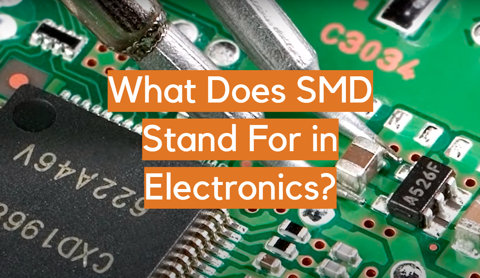
 Through Hole Technology is a vital aspect of electronics assembly. It involves mounting components on a printed circuit board (PCB) by inserting leads through holes on the board and soldering them in place. This technology is known for its durability and reliability, making it suitable for applications where robust connections are essential, such as in aerospace and automotive industries. Although surface mount technology (SMT) has gained popularity, THT remains a valuable choice for certain electronic components, providing a secure and enduring connection in various devices.






Leave a Reply