
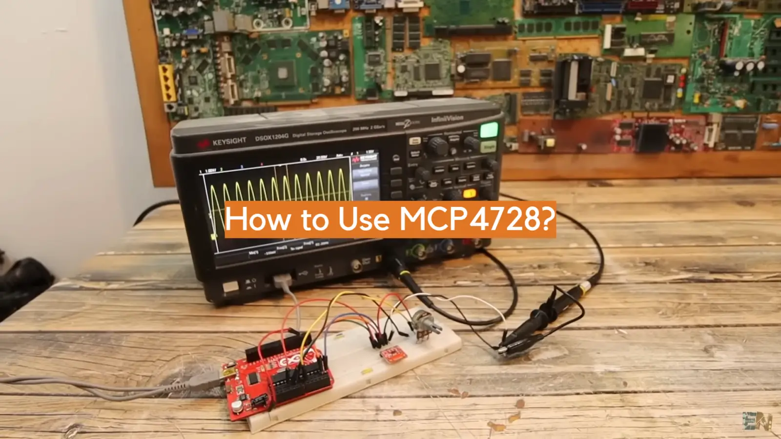
If you’re looking for a simple and intuitive way to unlock the power of MCP4728, you’re in the right place. This comprehensive guide to using MCP4728 will provide an easy-to-follow overview of its many features and capabilities, so you can start leveraging this powerful technology right away! With the help of this guide, you’ll be able to take full advantage of all that MCP4728 has to offer and use it to its fullest potential. So, what are you waiting for? Read on to find out more about MCP4728 and get unlocking today!
What is a PIC Frequency Counter for?
A PIC Frequency Counter is a device used to measure the frequency of an electrical signal. It works by counting the number of pulses or cycles per second that go through a circuit and then displaying this as a digital readout. A frequency counter can be used in many different applications including testing for accuracy on electronic systems, calibration of analog circuits, measuring radio frequencies, checking audio frequency response characteristics, and troubleshooting issues with power supplies.
With its precise readings and wide range of measurement capabilities, the PIC Frequency Counter is an invaluable tool for technicians and engineers alike. In addition to being versatile and accurate, the PIC Frequency Counter is also relatively inexpensive compared to other types of test equipment. This makes it easy to integrate into existing workflows and provides an economical way to measure frequency without sacrificing accuracy.
No matter what your application, the PIC Frequency Counter is sure to provide you with reliable and accurate results every time. From testing radio frequencies to troubleshooting power supplies, this device can help you get the job done quickly and efficiently. In addition, its low cost makes it a great choice for technicians on a budget who still need high-quality data. With its wide range of features and capabilities, the PIC Frequency Counter is sure to be an invaluable tool in any technician’s arsenal [1].
Specification: LCD frequency counter circuit
Description
The LCD frequency counter circuit is designed to measure and display the frequency of an input signal. It consists of a PIC microcontroller, an LCD, and three digital inputs – two for choosing between multiplexed or single-ended inputs of the signal to be measured, and one for selecting whether to measure 1MHz or 10MHz signals. The PIC microcontroller measures the frequency of the input signal by counting its period using its internal timer. The calculated frequency is then displayed on the LCD.
Overall, the LCD frequency counter circuit is an effective and reliable tool for measuring frequencies of various input signals in both laboratory and industrial applications.
Hardware Components
The LCD frequency counter circuit consists of the following components:
- PIC microcontroller
- LCD display
- Digital inputs (2 for multiplexed or single-ended signal input, 1 for 1MHz/10MHz selection)
- 12V DC power supply
Connections and Interfacing
The connections between the components are as follows:
- The digital inputs are connected to the PIC microcontroller’s port pins.
- The output signal from the PIC microcontroller is sent to the LCD display.
- The power supply is connected to all components in order to provide them with the necessary voltage and current.
In terms of interfacing, the LCD frequency counter circuit is designed to be user-friendly, with a simple and intuitive control menu. The user can easily select the measurement parameters such as multiplexed or single-ended input, 1MHz/10MHz selection, etc. by using the digital inputs.
Software
The LCD frequency counter circuit uses a PIC microcontroller to measure and display the frequency of an input signal. The PIC microcontroller contains the necessary software code for counting the period of the input signal to calculate its frequency. Additionally, there is also a control menu that allows users to easily select different measurement parameters [1].
Benefits of LCD frequency counter circuit
LCD frequency counter circuit is a great tool for measuring the frequency of various signals with high accuracy. Its advantages include:
- Easy to use and setup- LCD frequency counters are simple to assemble and operate. They come with clear instructions and help you quickly measure the frequency of any signal without complex wiring or calibration.
- Accurate measurements- LCD frequency counters can provide accurate measurements of frequencies up to 10 MHz with an accuracy rate of 0.001 Hz (0.1 ppm). This allows users to accurately determine the exact frequency of a signal in their system without having to worry about calibration errors or incorrect readings due to external factors like temperature, voltage, etc.
- Cost effective- LCD frequency counters are relatively inexpensive when compared to other frequency measurement systems. This makes them a great option for hobbyists and professionals who need to measure frequencies without spending too much money.
- Easy display- LCD frequency counters come with an easy-to-read display that helps users quickly identify the exact frequency of signals in their system. This eliminates any confusion or guesswork associated with conventional analog meters or similar devices.
- Versatile- LCD frequency counter circuits can be used for various applications including radio tuning, troubleshooting audio equipment, testing electronic circuits, and more. They can also be used in conjunction with digital oscilloscopes for detailed analysis of waveforms and signals.
- Durable design- LCD screens feature a durable construction that can withstand wear and tear over time. This ensures a longer-lasting product that will continue to provide accurate measurements for years to come.
Overall, an LCD frequency counter circuit is an invaluable tool for anyone who needs to measure frequencies with high accuracy and ease of use. The cost-effective design makes it great for hobbyists and professionals alike, and the versatile nature allows users to get more out of their frequency measurement systems. With all these features, an LCD frequency counter circuit is worth considering if you’re looking to take your frequency measurement projects to the next level!
Frequency Counter Using PIC16F628A (with Prototype PCB and Built-in Crystal Oscillator) for HAM Shacks
Step 1: Gathering the Parts
The parts you need to build this project are simple and inexpensive. They include:
- PIC16F628A microcontroller
- Prototype PCB for mounting the components
- Crystal oscillator
- Capacitors, resistors, LED’s and other components as required by the schematic
Step 2: Schematic Diagram and Wiring Scheme
The schematic diagram for the project is shown below:
This circuit consists of a PIC16F628A microcontroller and some other components. The crystal oscillator should be connected to pin 14 (RA6) and 15 (RA7). A 10k resistor should be connected between these two pins to ensure proper operation. Power from an AC adapter or battery pack can be used to supply the circuit with 5V DC. The LED’s are connected to digital outputs 0-7 on the microcontroller, for indicating frequency count status. The push button switch is connected to RB0, which is an external interrupt pin.
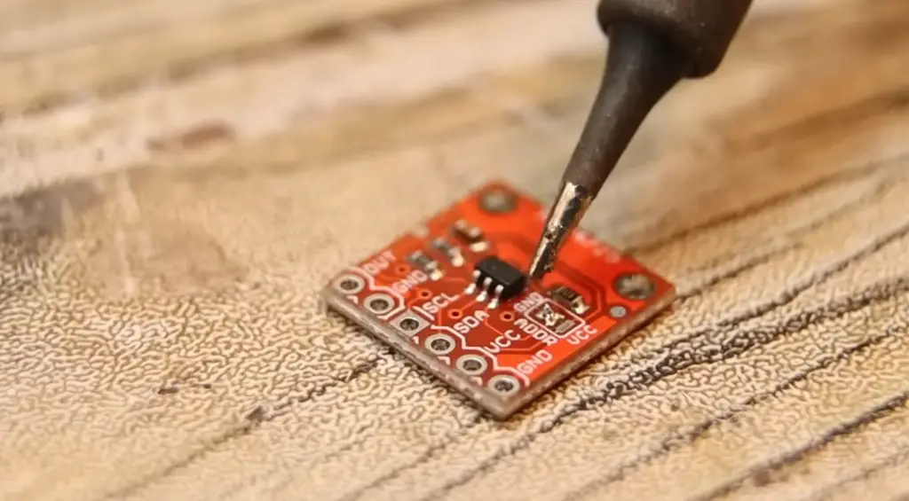
Step 3: Building the Hardware
Once you have the parts, it’s time to build the hardware. Start by soldering the components onto the PCB according to the schematic diagram. Make sure all connections are secure and free of any shorts. Once everything is soldered, insert the PIC16F628A chip into its socket on the board and connect the power.
Step 4: Editing the Software (Optional) and HEX for Burning the PIC
The software for this project can be downloaded from GitHub. It is written in assembly language, so you may need to make some changes if you want to customize it. Once the code is ready, compile it into a HEX file which can then be used to burn the PIC.
Step 5: Programming
Now that your circuit is built, it’s time to program it. To do this, you’ll need a suitable programmer such as PicKit or MPLAB-ICD2 from Microchip Technology Inc. Once you have these tools, follow the instructions to download and install them on your computer. Once done, use your programming software to upload the firmware onto your PIC microcontroller.
Step 6: Testing and Troubleshooting
Now that the hardware is built and the code is running, it’s time to test out the frequency counter. Make sure all connections are secure and power up the circuit. If all goes well, you should see your LED’s blinking according to the counts given by your frequency counter module. If you encounter any errors or unexpected behavior, check your connections first and then diagnose further using debugging tools such as an oscilloscope.
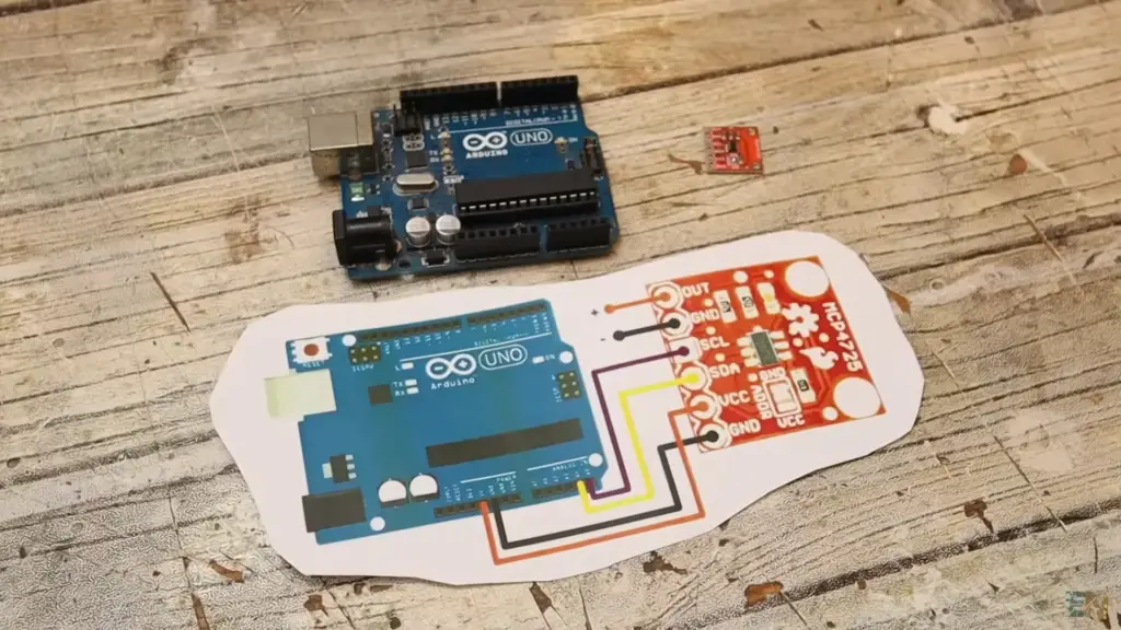
How can MCP4728 be used?
MCP4728 can be used for a variety of applications, including:
- Controlling the brightness of LEDs
- Creating custom waveforms
- Generating analog signals using digital input sources
- Modulating audio signals with pulse-width modulation (PWM)
- Implementing advanced control functions such as closed-loop sensorless motor control and variable speed drive systems.
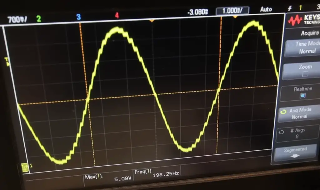
Additionally, MCP4728 is an ideal choice for creating low-distortion sine waves, as well as other complex output waveforms. It can also be used in combination with a microcontroller to create sophisticated high-precision measurement devices. Finally, MCP4728 can provide precise voltage measurements when combined with an ADC.
Types of signals you can measure using a Frequency Counter
A frequency counter measures the frequency of a signal and is an electronic device used for measuring frequency. It can measure the frequency of different types of signals such as:
- AC/DC signals – These are alternating current (AC) or direct current (DC) electrical signals that can be measured with a frequency counter.
- Audio signals – These are sound waves that can also be measured using a frequency counter.
- Radio frequency (RF) signals – RF signals refer to high-frequency electromagnetic radiation, and these too can be measured using a frequency counter.
- Digital signals – Digital signals consist of pulses or digital logic states, which can also be measured with a frequency counter. In addition, frequency counters can also measure the period of a signal, which is the time it takes for the signal to complete one full cycle.
Frequency counters are essential tools used in many different scientific and engineering applications, such as measuring the frequency of radio transmitters or oscillators. They are also used in communications systems to help ensure that signals stay within certain frequency ranges. By using a frequency counter, you can accurately measure frequencies and their associated parameters, which makes them an invaluable asset in any laboratory setting [3].
FAQ
What is a PIC Frequency Counter?
A PIC Frequency Counter is an electronic instrument or component that measures the number of cycles per second in an electrical signal. This type of device can be used to measure a wide range of frequencies from radio waves down to extremely low frequencies. It can also be used for the measurement of digital signals, such as pulse width modulation (PWM) signals. The frequency counter typically displays the results on a LED display, allowing readings to be taken quickly and accurately. Generally, these devices are small and portable, making them convenient for laboratory use and field work.
What is the difference between a Frequency Counter and an Oscilloscope?
Frequency counters are designed to measure frequency while oscilloscopes are better suited for measuring voltage amplitude levels over time. While oscilloscopes can be used to measure frequency, they are not as accurate as a dedicated frequency counter. Frequency counters typically come with more features than an oscilloscope such as automatic range switching, averaging, and temperature control. Additionally, many modern frequency counters offer computer connectivity for data acquisition and analysis purposes.
What types of signals can I measure using a Frequency Counter?
Frequency counters can be used to measure both periodic and non-periodic signals. Examples of signals that you can measure include sine waves, square waves, triangular waves, pulse width modulation signals (PWM), and various digital signal protocols such as I²C or UART. With the right type of probe or sensor connected to the input port of the frequency counter, you can measure signals from radio waves all the way down to extremely low frequencies.
What are some common applications of Frequency Counters?
Frequency counters are used in a variety of industries and for numerous purposes. Some examples include measuring PWM signals in automotive electronics, testing microcontroller speeds in computing devices, calibrating audio frequencies for sound systems, monitoring power line frequencies in electrical engineering projects, and measuring radio wave signals for communication technologies such as Bluetooth or Wi-Fi. Frequency counters are also commonly used by hobbyists and students who perform experiments and prototype designs that require precise frequency measurements.
Are there any safety precautions to consider when using a Frequency Counter?
When working with frequency counters, it is important to be aware of the range and voltage levels of the signals you are measuring. It is also important to ensure that your circuit design and probe connections are done correctly in order to avoid damaging the counter or other components. Additionally, when operating a frequency counter proper grounding techniques must be followed to avoid creating electrical hazards or interference on other devices. Always read all manufacturers’ instructions before using any device for measurements.
Are Frequency Counters expensive?
The cost of frequency counters can vary depending on their features and capabilities. For small jobs or hobby projects, less expensive models can be used with satisfactory results. However, for more intricate or rigorous work, higher-end models are often necessary. Generally speaking, simpler frequency counters may cost anywhere from a few hundred dollars up to USD 1000 while advanced models can range up to several thousand dollars or more.
How to use a PIC Frequency Counter?
Using a PIC Frequency Counter is relatively straightforward. First, connect the desired signal to the input port of the device and ensure that the connection is secure. Then, select your desired measurement settings such as range or averaging, and press start. The display will then show you an accurate reading of the frequency in Hertz (Hz). Depending on the model you are using, some additional features may be available such as graphing capability or computer connectivity. Be sure to read all instructions carefully before use for detailed information about how your particular model works.
What to avoid when using a PIC Frequency Counter?
When using a PIC Frequency Counter, it is important to avoid making connections on the input port with high voltages or frequencies that are outside of the counter’s range. Doing so may cause damage to the instrument or other components. Additionally, be sure to follow all safety guidelines and read all instructions before operating any device for measurements.
Why is it important to have a Frequency Counter?
Having an accurate frequency counter can be invaluable when working on projects that require precise measurements. This type of device can provide reliable and repeatable readings, allowing you to quickly identify any problems with your circuit or signal. By having the capability to measure all types of signals from low frequencies up to radio waves, frequency counters are incredibly versatile tools that can be applied in many different applications.
Are there any alternatives to Frequency Counters?
Yes, oscilloscopes are one alternative for measuring frequency especially when voltage levels also need to be taken into account. While they may not always be as accurate as dedicated frequency counters, oscilloscopes do offer other features such as graphing capabilities and computer connectivity which can be very advantageous. Additionally, various software programs such as Audacity or LabVIEW are available which allow you to measure frequency using your computer’s sound card and microphone. However, these methods may not always give you the most accurate results so if precision is key then a dedicated frequency counter might be your best option.
Overall, frequency counters are invaluable devices that provide quick and accurate readings for all types of signals from low frequencies up to radio waves. They come in a variety of sizes and feature sets making them suitable for many different applications. With the right precautions being taken when operating these instruments, they offer reliable measurements that can save time and money when troubleshooting circuits or analyzing data in the lab or field.
Where can I find more information about Frequency Counters?
For more information about frequency counters, there are many websites and organizations dedicated to providing detailed technical information. Additionally, the manufacturers of these devices often provide comprehensive product manuals which include setup instructions and safety guidelines.
Furthermore, online forums such as Reddit or EEVBlog have active communities where people post questions and discuss their experiences with various frequency counters. Finally, there are plenty of books available on the topic which provide in-depth explanations about how these instruments work and how to use them correctly. With all of this material readily available, you should be able to find plenty of resources for learning more about frequency counters.
What are the advantages of using a Frequency Counter?
Frequency counters offer numerous advantages over other methods of measuring frequency. They provide accurate and repeatable readings that can be used to isolate problems in circuits or detect errors in signal processing systems. Additionally, they are relatively easy to use with their simple interface and often feature computer connectivity which allows for data logging and graphing capabilities. Finally, due to their versatility, frequency counters can be used for many different applications such as sound systems or communication protocols. Overall, these devices offer reliable measurements that save time and money when troubleshooting or prototyping projects.
Useful Video: 12-bit DAC Arduino MCP4725 How To Use It – Stable Voltage Reffrence
Conclusion Paragraph
MCP4728 is an excellent choice for controlling a variety of analog systems. Its 12-bit resolution, low power consumption, and SPI interface make it ideal for a range of applications. Furthermore, its programmable gain amplifier allows flexibility in designing the system to meet different requirements. For those who want to control multiple channels with one IC, the MCP4728 has four separate DACs that can be accessed simultaneously through the SPI bus. These features make the MCP4728 an ideal solution for a variety of projects requiring analog-to-digital conversion and voltage output.
References
- https://www.best-microcontroller-projects.com/pic-frequency-counter.html
- https://www.best-microcontroller-projects.com/mcp4728.html
- https://www.ee-diary.com/2022/07/high-frequency-counter-with-arduino.html