
Building a CNC machine can be an extremely rewarding experience. Not only will you have a custom-built machine to help with your projects, but you’ll also have learned a great deal about the inner workings of CNC machines and Arduino in the process! In this article, we will answer some common questions about building a CNC machine with Arduino. We’ll provide useful tips and advice on how to get started, as well as information on the different parts that are necessary for construction. Let’s get started!
Why CNC Machine is a Great Project for Arduino
It’s used to control electronic devices and can be programmed to accept input, process data, and provide output through various sensors, servos, relays, etc. Arduino boards are easily available and come in a variety of sizes with different features.
It works by following a predetermined set of instructions called G-code which tells it how to move its motors as well as how fast they should move them. This makes it possible for the CNC machine to accurately produce complex shapes and parts with a very high level of precision.
Because Arduino is a great platform for creating custom electronics projects that require precise control over motors, servos or other outputs, CNC machines are an ideal project to build with it. With a well-built CNC machine, you can create intricate designs and shapes with greater accuracy than ever before.
The best part about building your own CNC machine is that it’s relatively easy to do so using off-the-shelf components and the open source Arduino platform. This guide will walk you through all the essential steps necessary to build your very own Arduino-based CNC drawing machine. [1]
Gather the Necessary Materials
Obviously, the first step in building a CNC machine with Arduino is to gather all the necessary components.
Used DVD writers
One of the components used in building a CNC machine with Arduino is a DVD writer. This will provide the necessary stepper motor for linear motion and rotational control. The motors are usually found on the head of the DVD drive, but be aware that some drives may not have them installed.
Screws, nuts and bolts
The next step is to gather all screws, nuts and bolts that may be needed during assembly. There should also be enough of each type to make sure everything fits together properly. It’s best to use high-quality materials here as they will last longer and ensure a smooth operation of your CNC machine.
A few pieces of aluminum
You’ll also need a few pieces of aluminum and/or wood to form the base structure of your CNC machine. These should be cut to size using a saw and then sanded down for a better fit. The aluminum and/or wood should also be strong enough to support all components placed on it.
You will specifically need 120mm long pieces of L shaped aluminum for this project.
Arduino UNO
Of course, one of the main components for a CNC machine is the Arduino UNO. This will be used to control all the motors and other electronics inside your CNC machine. Make sure to get the latest version of the Arduino as this will ensure maximum compatibility with third-party components.
Servo motor
Another important component of the CNC machine is a servo motor. This will be used to move the head of the machine in both directions, providing linear motion along two axes. Servos are generally more reliable than stepper motors and can provide higher accuracy.
CNC Shield
Next, you will need a CNC shield, which is essentially an Arduino shield that connects the motors to the Arduino. It provides the necessary electrical connections for controlling stepper motors and other components of a CNC machine. The shield works by providing a separate power supply, which allows the user to precisely control each component with separate signals. This is especially useful when building more complex machines such as 3D printers or milling machines. Make sure to get a reliable CNC shield as this will ensure maximum compatibility with third-party components.
L293D IC
The L293D IC will be used to control the motor’s speed and direction. This is an electronic component that allows you to easily adjust the speed and direction of your motors. It’s especially useful for controlling stepper motors, which are often used in CNC machines.
Flexible wires
Last but not least, you will need flexible wires to connect all the components together. These should be of good quality and long enough to reach from one component to another. Be sure to make use of shrink tubing where necessary for extra protection. [2], [3]
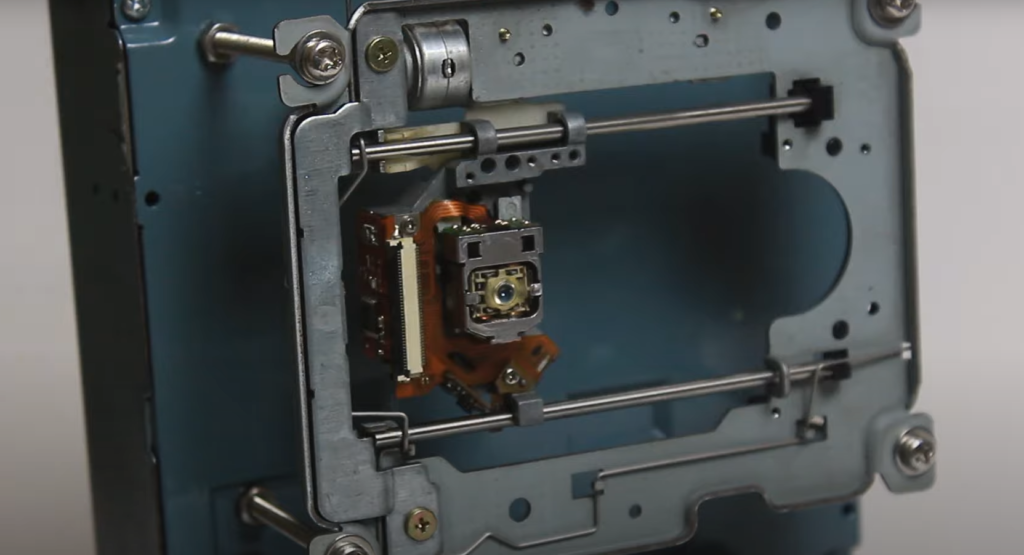
Remove the Unnecessary Parts of Your DVD Writer
The next step to building a CNC machine with Arduino is to remove the unnecessary parts of your DVD writer. Begin by removing the lens driving assembly. This is typically done by unscrewing two small screws on the side of the DVD writer. Once these screws have been removed, you can pull out the lens driving assembly from its enclosure.
Next, you’ll need to remove the disk driving motor. You won’t need it for this project at all so you can just pull it out from the bottom of the DVD writer.
The one thing you absolutely shouldn’t remove is the stepper motor. This is the motor that will be used to drive your CNC machine and you’ll need to keep it intact. Take a look at the other components near the stepper motor and verify that they all still seem functional. [2]
Solder Wires to the Stepper Motor
This step will require some soldering skills. You’ll need to solder the wires to the four points on your stepper motor. Make sure to use the correct type of soldering iron and solder for the job. Additionally, you should use heat shrink tubing on any exposed wires for extra protection. [2]
Mark the Drill Holes on Aluminum
Now it’s time to take those pieces of aluminum you prepared earlier and mark out the drill holes. This will depend on the size of your stepper motor but as a general rule, try to keep them around 2-3 cm apart. Once you have marked the drill holes, use an electric drill to punch through the aluminum. Make sure that all of your drill holes are perfectly aligned before proceeding further.
Then, drill both the lens assemblies by using the aluminum with small screws. This will help to secure them in place and make sure that everything is properly connected.
Once done, it’s time to assemble the body of your CNC machine. Take the aluminum pieces and screw them together, making sure that all components are properly connected. Vertical stepper motor should be the Y-axis while horizontal should be the X-axis. [2]
Create a Bed for a Paper
Since we will be creating a drawing machine, the next step is to create a bed for paper. You can make this bed out of wood or any other suitable material. Make sure that it’s big enough to fit your paper and sturdy enough to hold the weight of your drawing machine.
If the material is too big for your CNC machine, you can always cut it down to size using a saw or jigsaw.
You will also need to stick the bed with something. Use some glue on the moving part of the lens assembly and attach it to the bed. Make sure you can freely move the bed afterwards as you still want some mobility. [2]
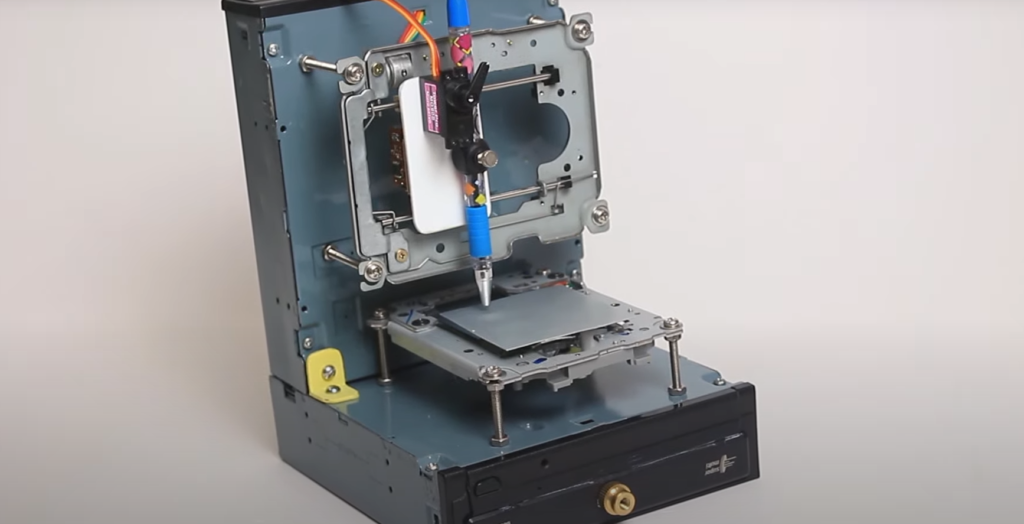
Create a Pen Holder
Your machine will also need something to draw with. The easiest way is to use a pen holder that can be easily attached to the stepper motor. You can make a simple pen holder using some plastic or metal, depending on your choice.
If you have a spare DVD writer, you can cut it and use it as the pen holder. Make sure your pen sits snugly in the holder and is held firmly.
Once you have created a suitable pen holder, attach it to the y-axis with screws or any other appropriate method. Make sure that it can move freely along the stepper motor’s rail without getting stuck.
The pen holder will not only hold a pen, but also will function as a Z-axis for your CNC machine. [2]
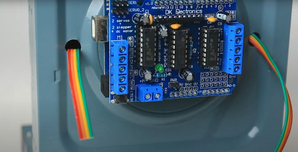
Place Arduino on the Aluminum Part of the Construction
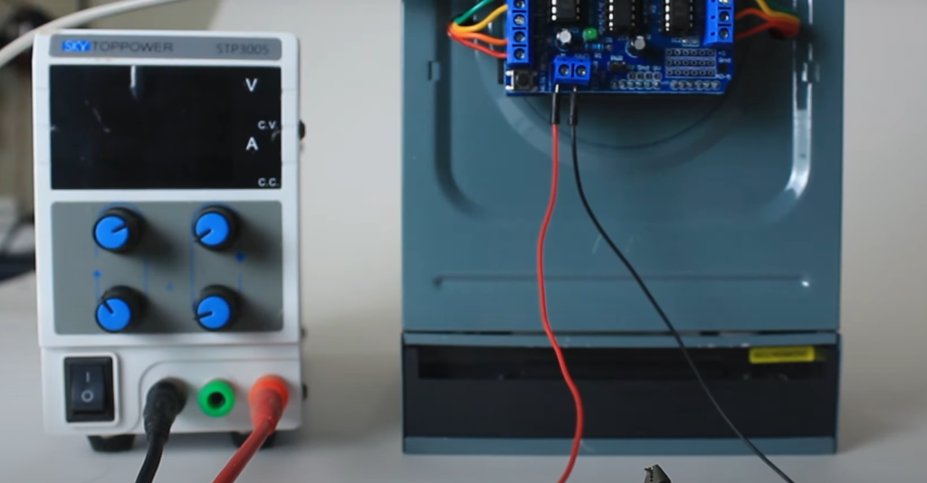
Now you have all the components of your CNC machine ready, it’s time to start putting them together. Place the Arduino on its designated aluminum part of the construction and use some small screws to secure it in place. You may need to drill a few holes first if they are not already present.
Once done, connect all the cables between various components of your CNC machine using appropriate connectors. Make sure that all wires are properly secured in place and there is no risk of any short circuits occurring due to loose connections.
And don’t forget to insert a CNC shield into the Arduino to enable it to control the stepper motor. Connect the x-axis stepper motor to the x-axis output of the shield and y-axis stepper motor to the y-axis output of the shield. This should be done before connecting any other components of the CNC machine. [2]
Programming Your CNC Machine
Now it’s finally time to write the code for your CNC machine. The first step for programming your CNC machine is to install an appropriate IDE on your computer. This will enable you to write commands using a text editor so that your Arduino can interpret them correctly.
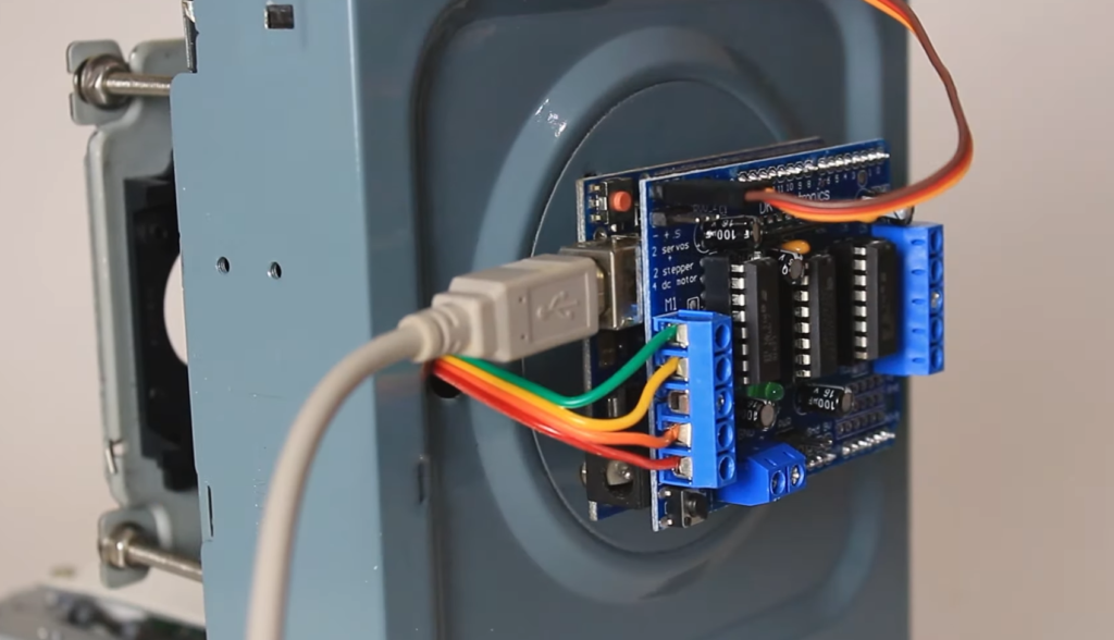
Once installed, connect your computer with Arduino using USB cable and launch the IDE. After that, open the source code file of the CNC machine (you can find these online).
When setting everything up, make sure to select the correct COM port. This is important for uploading the source code to your Arduino board. Repeat the same with a board type and other parameters.
Once you are all set, write the code for your CNC machine following the instructions of the source code and upload it to your Arduino board. The final step is to test if everything works as intended.
After you successfully uploaded the code, it’s time to open the G Code Sender program to test if your machine is ready.
It is used to create instructions for the CNC machine to follow, allowing it to accurately cut shapes and 3D objects from a variety of materials. G Code consists of text-based commands that tell the CNC what movements should be made and when.
The instructions are often very detailed, with exact coordinates being specified for each movement or operation that needs to be performed. This level of detail allows the CNC machine to produce extremely accurate results with minimal human intervention required during the machining process.
In the G Code program, you too will have to select a COM port, board type and other parameters. Before sending the G Code to your CNC machine, make sure to check if everything is in place. After double checking everything, hit the load G-code button and choose the file you want to draw!
Once the G Code is sent, your machine will start running and you can observe if it works according to your expectations. If any errors occur or something doesn’t work as intended, double-check all settings and connections before trying again. [2]
Fix Mirror Image Issue
One of the most common issues that people face while programming their CNC machine is a mirror image issue. This happens when the CNC machine produces the wrong output – instead of producing the desired design, it makes its mirror image.
To fix this issue, you need to find the cause of it first. The most common mistakes are reversing the direction of one or more axes or misinterpreting the units (inches vs centimeters). Check if any of these settings were incorrect and adjust them accordingly.
If you took a note of which axis is reversed when you connected the stepper motors, then this is an easy fix – simply switch the wiring of the corresponding axis and make sure that it’s properly secured. [2]
How to Convert an Image Into G-Code
So now you know that you need G-Code for your CNC machine, but how do you generate it? The easiest way is to use a G-Code converter that can transform an image or design into the code needed for your CNC machine.
There are many converters available online – some of them are free, while others require a one-time purchase or subscription. Before using any converter make sure to read up on its features and compatibility with your CNC machine model.
One of the most popular converters is Inkscape, a free vector-based graphics software. Inkscape can be used to convert an image into G-Code and can produce high quality results with minimal effort. Just download an extension that will allow you to save the final file as G-Code before starting.
To use the converter, simply upload the image you want to convert into G-Code and then adjust the necessary settings. One of the most important steps is setting all the units to inches. This is especially important if you are working with images of different sizes.
Then, choose the Trace Bitmap from the menu and select an appropriate threshold. This will allow Inkscape to identify various levels of shades in the image so that it can convert it into a binary file.
Once you are done adjusting all the necessary settings, hit Ok and move the image to the right position. Again click on Trace Bitmap and select Object to Path from the list of available options. After that, hit Dynamic Offset, save and choose the location where you want to save the file.
Now your image has been converted into G-Code and you can use it with your CNC machine! Just make sure to double check all settings before starting the machining process. [2]
FAQ
What is G code in CNC?
G code consists of simple commands that control how the machine will move. It is usually written as a set of instructions in text format and can be used to create intricate designs or control automated machinery.
The basic structure of G code instructions consists of a letter followed by a series of numbers. The letters specify which type of movement the machine should perform, while the numbers provide information such as speed, distance, or feed rate.
Luckily, for simpler tasks you can just convert vectors and 3D models into G code directly from software. This saves you the time of having to program it from scratch, but if you want to get really creative, you can also write your own G code instructions.
How do I program my Arduino CNC machine?
Programming your Arduino CNC machine is relatively straightforward, although a bit time consuming. To get started you first need to have the necessary components in place: an Arduino board (preferably a UNO or similar variant), a CNC machine and G-code software. Once all of the components are in place, you can start programming your CNC machine.
First, you need to upload the source code to Arduino IDE (Integrated Development Environment) by connecting the Arduino board to your computer. Then, you will need to send an image or vector file to the Arduino board using a G-code software. Once the G-code has been uploaded, you can start running a test to ensure everything is working properly.
Is GRBL the same as G-code?
No, GRBL is not the same as G-code. GRBL (G-code sender) is an open-source software that interprets G-code and controls CNC machines like 3D printers, milling machines, laser cutters, etc. It is designed to run on small microcontrollers such as Arduino boards. G-code, on the other hand, is a language used to control machine tools in a more abstract way by specifying certain parameters of the tool path and movement of the parts being machined.
Do CNC machines require any programming?
Yes, CNC machines require programming in order to make them work. The program is written in a language called G-code, which is a series of commands that tell the machine what to do and how to move. Generally, programs are written in CAD/CAM software like Mastercam or Fusion 360 and then converted into G-code so the machine can read it.
When it comes to building your own CNC machine with an Arduino microcontroller, you don’t need any prior programming knowledge. However, if you’re looking for more advanced features like motion control or feedback systems, then some coding experience would be beneficial.
What are the 3 key components of a CNC machine?
The three key components of a CNC machine are the processing equipment, the control system, and the mechanical structure.
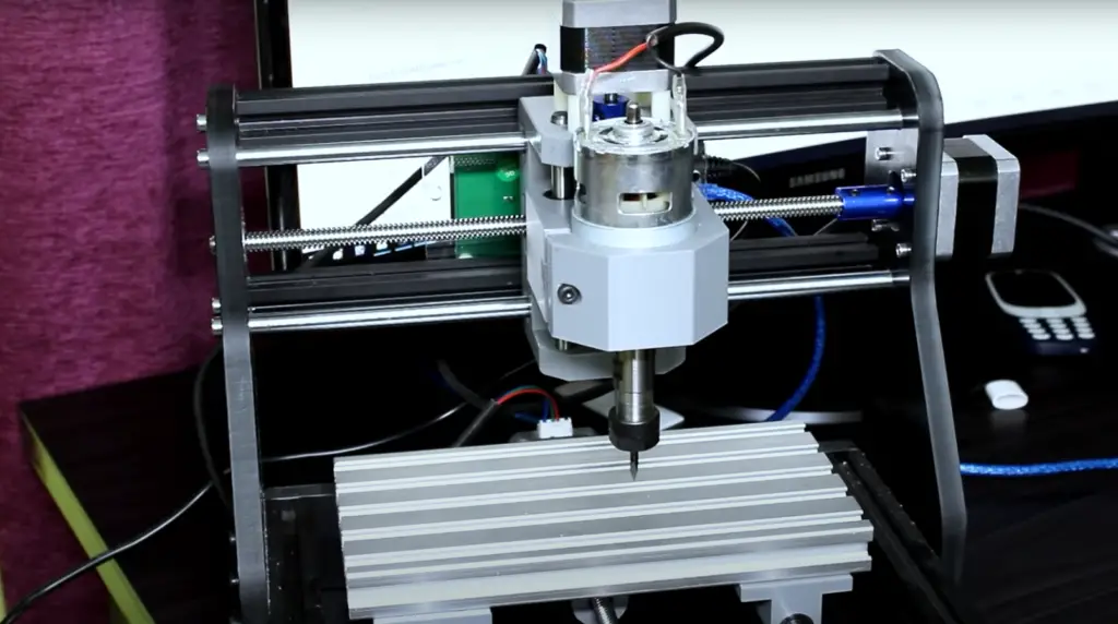
Processing equipment consists of a spindle motor, drive motor, and tooling. The spindle motor is responsible for spinning the cutting tool in order to cut through material. The drive motor is responsible for moving the cutting head along three axes: X, Y, and Z. Tooling can range from drill bits and router bits to saws and grinders depending on your project needs.
Useful Video: How to make Arduino Mini CNC plotter machine
Conclusion
Arduino is an extremely versatile tool for constructing a variety of projects, including CNC machines. The components required for a basic machine are relatively inexpensive and the programming and construction process is straightforward. Before committing to a particular project, it’s important to consider all of the factors that could influence your design such as size, accuracy, speed, materials used, and complexity. With careful planning and consideration while building your CNC machine with Arduino, you can create a highly efficient and effective device tailored to your particular needs.
In this article we explained the key components of a machine, discussed the most important considerations when constructing your CNC machine, and provided step-by-step instructions on how to build a CNC machine with Arduino.
In addition to that, we also explained what you should do if you get a mirrored image, how to calibrate the program and many other useful tips.
We hope this guide has provided you with some useful tips on how to build a CNC machine with Arduino! Have fun and good luck on your projects! Thanks for reading!
References
- https://learn.sparkfun.com/tutorials/what-is-an-arduino/all
- https://create.arduino.cc/projecthub/shubhamsuresh/how-to-make-mini-cnc-machine-7f4bf7
- https://www.instructables.com/DIY-Arduino-CNC-Machine/