If you’re an avid electronics enthusiast, then you know that the potential of Arduino is near limitless. But to tap into its full potential requires a level of expertise that can be hard to come by. Thankfully, this guide is here to provide a comprehensive look at how to use analog output with Arduino – unlocking its full capabilities and taking your projects to the next level. With these instructive steps on analog output, you’ll be well on your way to becoming an Arduino master!
How Arduino Analog Output PWM works
PWM Output Smoothing
PWMs are capable of providing a much smoother output than regular digital pin outputs. This is because the amount of power sent to the pin can be varied over time instead of being either on or off. By varying the duty cycle (proportion of time during which the signal is active) and frequency, an analog effect can be achieved that can provide smooth transitions between different levels of voltage. This allows for more precise control over a circuit, as well as reducing any noise generated by abrupt changes in power.
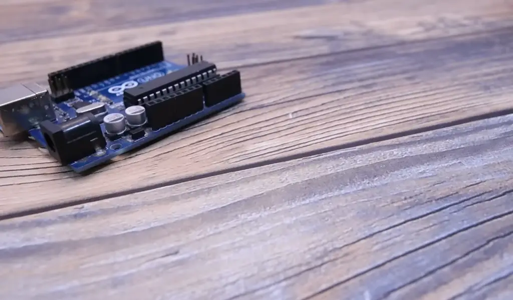
The main advantage of using PWM over regular digital pins is its ability to vary the intensity without affecting the frequency. This means that higher voltages can be obtained at lower frequencies, allowing for more efficient use of energy and quieter operation. It also makes it easier to control the intensity of LEDs, as the duty cycle can be used to adjust the brightness without changing the frequency. By adjusting both the frequency and duty cycle, a wide range of voltage levels can be achieved, allowing for more precise control over circuits.
PWM can also be used to reduce power consumption, as pulses can be sent at a lower frequency when full power is not required. This allows for more efficient use of energy and quieter operation.
Capacitive Resistive pair
The Capacitive-Resistive pair is used to create a variable resistor. This technique utilizes a capacitor and resistor in series to create an adjustable voltage divider. The capacitor acts as a charge storage device, while the resistor determines how quickly the charge can be released. By adjusting the resistance, the output voltage can be varied, allowing for more precise control over a circuit. This technique can also be used with PWM to vary the duty cycle and frequency of pulses sent to the pin, further increasing its precision and efficiency.
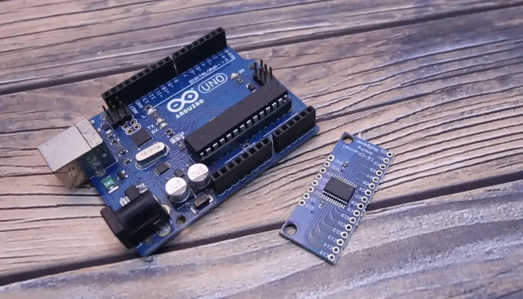
By combining these two techniques, Arduino Analog Output PWM provides users with powerful tools for controlling their circuits with precision and efficiency. From LED brightness control to power conservation, this technology has many uses that make it a valuable tool for makers and engineers. Arduino provides an extensive library of functions that makes it easy to use PWM, allowing users to quickly set up their projects without needing to understand the complex details of this technology.
Inductive Resistive Pair
The Inductive-Resistive pair is used to create an adjustable transformer. This involves using a coil and resistor in series to create an adjustable voltage divider. The coil acts as a current storage device, while the resistor determines how quickly the charge can be released. By adjusting the resistance, the output voltage can be varied, allowing for more precise control over a circuit. This technique also allows for greater efficiency when transmitting signals over long distances by reducing noise and interference.
Persistence of vision (POV)
Persistence of vision (POV) is a technique used to create the illusion of motion. This is done by rapidly flashing LEDs in sequence or varying their intensity while keeping them on for short periods. By doing this, it appears as if the light is moving across the circuit instead of staying stationary. This effect can be achieved with Arduino Analog Output PWM by adjusting the duty cycle and frequency of pulses sent to each LED.
Arduino PWM Frequency
Arduino PWM Frequency is the speed at which a pin alternates between high and low voltage states. The frequency can be adjusted to achieve desired effects, such as LED brightness control or controlling motor speeds. Adjusting the frequency also reduces power consumption and noise generated by abrupt changes in power. The default PWM frequency on Arduino Uno boards is 490Hz, but this can be changed using the analogWriteFrequency() function [1].
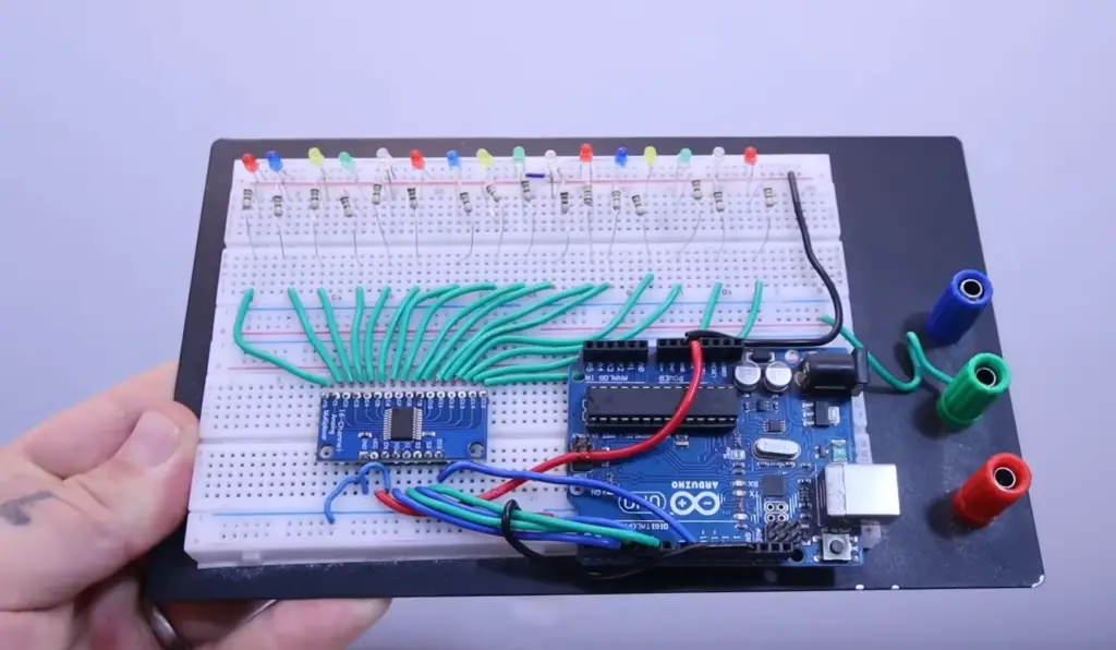
Arduino Analog Output Pins for PWM
PWM Resolution Waveforms
The Arduino board has six analog output pins marked A0 – A5. These can be used to produce Pulse Width Modulation (PWM) signals, which are a type of digital signal with varying pulse widths. The resolution of the PWM waveform is determined by the number of bits in the analog-to-digital converter, or ADC, present on the board. Generally speaking, higher-resolution PWM signals result in smoother and more accurate waveforms.
The Arduino board supports two types of PWM waveforms: 8-bit resolution and 10-bit resolution. 8-bit resolution gives 255 possible levels of duty cycle, while 10-bit resolution provides 1024 levels of duty cycle. To use these different resolutions for your PWM waveforms, you’ll need to adjust the relevant registers in the Arduino board.
The pins A0 – A5 are capable of producing two types of PWM signals: fast and slow. Fast PWM provides a higher frequency signal with a variable duty cycle, while Slow PWM outputs a low-frequency signal with a fixed duty cycle. You can use the appropriate register settings to switch between these different types of waveform output.
You can also use analogWrite() on pins A0 – A5 to generate 8-bit resolution or 10-bit resolution PWM signals using the analogWrite function. This makes it easier for users to quickly create their custom waveforms without needing to manually adjust the relevant registers [2].
PWM frequency 490Hz (default)
The default PWM frequency for pins A0 – A5 on the Arduino board is 490Hz. This means that each pulse in the analog output waveform will have a period of 2ms (1/490). You can use this as a basis for further calculations, such as calculating the total time it takes to produce one duty cycle.
You can also use the analogWriteFrequency() function to change the PWM frequency of the pins A0 – A5. This allows you to customize your waveforms and fine-tune their accuracy and resolution. The analogWriteFrequency() function supports frequencies between 31Hz and 4Khz, so you should be able to find a suitable value depending on your application requirements.
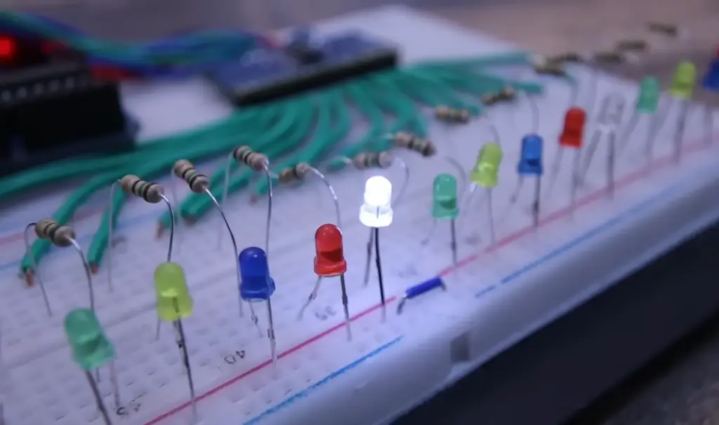
PWM frequency 980Hz (maximum)
The maximum PWM frequency for the pins A0 – A5 on the Arduino board is 980Hz. This means that each pulse in the analog output waveform will have a period of 1 ms (1/980). You can use this as a basis for further calculations, such as calculating the total time it takes to produce one duty cycle.
You can also use the analogWriteFrequency() function to change the PWM frequency of these pins. This allows you to customize your waveforms and fine-tune their accuracy and resolution. The analogWriteFrequency() function supports frequencies between 31Hz and 4Khz, so you should be able to find a suitable value depending on your application requirements.
Example Sketch Sine Generation
Loop delay 1ms Output
This example demonstrates a simple sketch that uses a loop delay of 1 ms to generate a sine wave. This example is useful for understanding the basic principles behind creating an audio signal with Arduino.
The code below will produce a sine wave at the frequency of 440 Hz, which is the note A4 on most keyboards. The output can be viewed using an oscilloscope or other visualization tool.
// Define constants
const int sampleRate = 44100; // Sample rate (44100 samples per second)
const double sineFrequency = 440; // Frequency of the note A4 (440 Hz).
const int numberOfSamples = 1000; // Number of samples to generate in the wave.
// Create variables to store samples
double sample; // Variable to store one sample at a time
double sineWaveSample; // Variable to store the sine wave sample value
// Begin looping through each sample in the waveform
for (int i = 0; i < numberOfSamples; i++) {
// Calculate current sample value and save it in a buffer
sineWaveSample = sin(2 * PI * i * sineFrequency / sampleRate);
sample = sineWaveSample;
// Delay for 1 milliseconds and send the new output signal
delay(1);
Serial.println(sample);
}
The output of the sketch can be used to generate a sine wave on an Arduino board or other device. The code could also be modified to produce different waveforms such as square waves, sawtooth waves, and triangle waves. If you have access to an oscilloscope, it can be used to view the generated signal in real time.
The code above provides a basic example for generating sine waves with Arduino, but it is possible to create more complex signals by altering the code or using different libraries. Experimenting with different waveforms can help you understand how sound works and allow you to create your own unique sounds!
Loop delay 185us Output
This example demonstrates a simple sketch that uses a loop delay of 185 us to generate a sine wave. This example is useful for understanding the basic principles behind creating an audio signal with Arduino.
The code below will produce a sine wave at the frequency of 440 Hz, which is the note A4 on most keyboards. The output can be viewed using an oscilloscope or other visualization tool.
// Define constants
const int sampleRate = 44100; // Sample rate (44100 samples per second)
const double sineFrequency = 440; // Frequency of the note A4 (440 Hz).
const int numberOfSamples = 1000; // Number of samples to generate in the wave.
// Create variables to store samples
double sample; // Variable to store one sample at a time
double sineWaveSample; // Variable to store the sine wave sample value
// Begin looping through each sample in the waveform
for (int i = 0; i < numberOfSamples; i++) {
// Calculate current sample value and save it in a buffer
sineWaveSample = sin(2 * PI * i * sineFrequency / sampleRate);
sample = sineWaveSample;
// Delay for 185 microseconds and send the new output signal
delayMicroseconds(185);
Serial.println(sample);
}
FAQ
How to use analog outputs on Arduino?
Analog outputs on Arduino can be used to control the brightness of a LED, for example. To use the analog output, connect an LED to one of the digital pins and set it as an OUTPUT in your program. Then use the `analogWrite()` function with a value from 0-255, which is equal to a duty cycle percentage of 0-100%. The higher the value, the brighter the LED will be. You can also use analog outputs to create sounds or drive servos and other types of motors.
Can Arduino control multiple motors?
Yes, Arduino can be used to control multiple motors at once if you have enough PWM pins available. You can use a motor shield, such as the L293D, to control up to two DC motors or one stepper motor. Additionally, you can also use the I2C bus to drive multiple servo motors.
Can Arduino be used as a data logger?
Yes, Arduino can be used as a data logger with the help of an SD card and some sketch programming. You can store time-stamped sensor readings in CSV files that can be opened in a spreadsheet application or analyzed on your computer. For more advanced uses, you might need an external device for high-speed data logging.
What is the best way to start with Arduino?
The best way to start with Arduino is by familiarizing yourself with the basics. Start by understanding the pinout of your board and learning how to wire components together. Then, learn how to write a basic sketch program in the Arduino IDE. Finally, dive into more advanced topics like connecting external devices or writing complex sketches.
How many analog outputs does an Arduino have?
Most Arduino boards have 6 analog outputs, which are labeled A0 through A5. These pins can be used to send PWM signals that can control the brightness of a LED or drive servos and other types of motors. Additionally, some boards have more than 6 analog outputs. It means you can use them to measure up to 16 analog signals.
Does Arduino support wireless communication?
Yes, Arduino supports a variety of different wireless communication protocols. The most popular ones are Bluetooth and WiFi, which enable devices to wirelessly connect and exchange data over a network. Additionally, other protocols such as Zigbee or LoRaWAN can be used for long-range applications.
Can I program Arduino with Python?
Yes, you can program your Arduino using Python with the help of libraries such as pyserial or pyFirmata. These libraries allow you to communicate with your board over USB or serial connections and send commands to control digital or analog pins, as well as other peripherals.
Can Arduino be used for robotics?
Yes, Arduino can be used for robotics projects. It is a great platform that can easily be integrated with various sensors, motors, and other components. Additionally, it can also be programmed using different languages such as C/C++ and Python, which makes it versatile and easy to use.
What is the maximum current that can be drawn from an Arduino pin?
The maximum current that can be drawn from an Arduino pin is 40mA. This is enough to power a small LED or motor, but not enough to power larger motors or components that draw a lot of current. In these cases, you will need an external device such as a motor driver or relay board to supply the required current.
Can an analog have 1024 values on an Arduino?
Yes, an analog input on an Arduino can have 1024 values. This is achieved by using the `analogRead()` function, which reads an analog voltage value from 0 to 5 volts and converts it into a digital value from 0 to 1023.
Can I control multiple devices with one Arduino board?
Yes, you can control multiple devices with one Arduino board. You will need to use special breakout boards or shields such as motor controllers, radio transceivers, or WiFi modules. These will allow you to connect and communicate with your external devices and control them through sketches in the Arduino IDE.
How to read analog values from Arduino?
Analog values can be read from Arduino with the help of the `analogRead()` function. This function reads an analog voltage value from 0 to 5 volts and converts it into a digital value from 0 to 1023. You can then use this value to control things such as LED brightness or motor speed.
Can I use Arduino for Home Automation?
Yes, Arduino can be used for home automation projects. With the help of sensors, actuators, and other components, you can create a custom automation system that is tailored to your needs. Additionally, you can program it using languages such as C/C++ or Python so that it is flexible and easy to use.
Can Arduino control a servo motor?
Yes, Arduino can be used to control a servo motor. To do this, you will need an external power supply and connect the signal pin of the servo directly to one of the digital pins on your board. Then, you can use the `servoWrite()` function in your sketch program to set the position or speed of the motor.
What is PWM output?
PWM (pulse width modulation) output is a type of analog output from an Arduino board that allows you to control things such as LED brightness or motor speed. It works by sending a series of digital pulses, where the width of each pulse is proportional to the desired value.
Can Arduino be used to read temperature?
Yes, Arduino can be used to read temperature with the help of an external temperature sensor. These sensors are usually connected directly to one of the analog pins on your board and then programmed in your sketch program using the `analogRead()` function.
What type of motors can I control with an Arduino?
You can control a variety of DC motors or stepper motors with an Arduino board. To do this, you will need an external motor controller that is connected to your board and programmed using the `analogWrite()` function in your sketch program. Additionally, brushless motors can also be controlled with special motor drivers.
Can Arduino run a computer?
No, an Arduino board cannot run a computer, as it does not have the necessary processor or memory capacity to do so. Instead, it is used as an embedded platform that is used to control external components such as sensors, motors, and displays. Be sure to check out our tutorials for more information!
Can Arduino control a camera?
Yes, Arduino can be used to control a camera. To do this, you will need an external camera module that is connected to your board and programmed using the `digitalWrite()` function. This will allow you to take pictures or record videos with your camera from the comfort of your computer or phone.
Can I program Arduino without a computer?
Yes, you can program your Arduino without a computer with the help of an external USB programmer or a bootloader. These will allow you to upload sketches directly from your phone or tablet and make changes without needing to connect them to your computer. Be sure to check out our tutorials for more information on how to do this!
Can I use Arduino for AI projects?
Yes, Arduino can be used for AI projects such as image recognition or voice control applications. To do this, you will need special shields that are compatible with your board and programmed using libraries such as TensorFlow Lite or Google Edge TPU. Additionally, some boards also have built-in hardware accelerators which can increase the performance of these types of projects.
Useful Video: Arduino Multiplexor – MUX INPUTS & OUTPUTS – ANALOG and PWM
Conclusion Paragraph
Arduino analog output is a great way of controlling and reading data from various devices, making it an ideal choice for projects that require custom programming and high precision. With the wide range of libraries available to developers, Arduino makes it easy to control servos, read sensors, and create sophisticated interactive systems with little effort. As more people discover the possibilities offered by this powerful microcontroller platform, we can expect Arduino analog output capabilities to continue to be put to creative use in diverse applications.
References
- https://www.best-microcontroller-projects.com/arduino-analog-output.html
- https://linuxhint.com/pwm-pins-arduino-uno/








Leave a Reply