The crankshaft sensor plays a pivotal role in the intricate dance of components that make an internal combustion engine come to life. Responsible for monitoring the position and rotational speed of the crankshaft, this sensor ensures precise fuel injection and ignition timing, contributing to the engine’s smooth operation. However, like any electronic component, crankshaft sensors are not immune to wear and tear, potentially leading to performance issues or engine malfunctions.
Understanding how to test a crankshaft sensor is a valuable skill for any automotive enthusiast or DIY mechanic. In this guide, we will explore the essentials of using a multimeter, a versatile tool in almost every toolbox, to diagnose and troubleshoot crankshaft sensor problems. Whether you’re seeking to diagnose a persistent engine issue or simply aiming to enhance your automotive troubleshooting skills, this step-by-step tutorial will empower you to unravel the mysteries behind a crankshaft sensor’s functionality and confidently pinpoint any issues. So, grab your multimeter, and let’s embark on a journey to demystify the testing process and ensure your engine runs with the precision it deserves. [1]
Understanding the Multimeter
Before we dive into testing a crankshaft sensor, let’s familiarize ourselves with the basic functions of a multimeter. A multimeter is a versatile electronic tool that combines several measurement functions into one device. It typically includes settings for measuring voltage, current, and resistance, making it an indispensable tool for diagnosing electrical issues in various applications, including automotive systems.
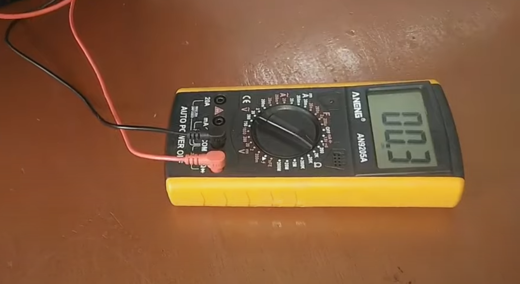
Explanation of Multimeter Functions:
- Voltage (V): This setting allows you to measure the electrical potential difference between two points in a circuit. When testing a crankshaft sensor, you’ll likely use this function to measure the voltage output.
- Current (A): The current setting is used to measure the flow of electrical current in a circuit. While testing a crankshaft sensor, you may not need this setting as the sensor typically produces a voltage signal rather than a current.
- Resistance (Ω): Resistance is the opposition to the flow of electrical current. When testing a crankshaft sensor, the resistance setting is crucial for evaluating the sensor’s internal resistance.
Setting Up the Multimeter for Testing:
- Select the Appropriate Setting: For testing a crankshaft sensor, you’ll primarily use the resistance setting (Ω). Consult your multimeter’s user manual to locate and select the resistance setting on the dial [2].
- Check the Sensor Specifications: Before connecting the multimeter, refer to the crankshaft sensor’s specifications in the vehicle’s repair manual or documentation. This information will guide you on the expected resistance values for a healthy sensor.
- Power Off the Vehicle: Ensure that the vehicle’s ignition is turned off before connecting the multimeter. This precautionary step is essential for safety and accurate readings.
- Locate the Crankshaft Sensor: Identify the location of the crankshaft sensor in your vehicle. It’s typically positioned near the crankshaft and may require some disassembly or access to reach.
- Disconnect the Sensor: Carefully disconnect the electrical connector from the crankshaft sensor. This isolates the sensor from the vehicle’s wiring harness, allowing you to measure its resistance without interference.
- Connect the Multimeter: Attach the multimeter probes to the sensor’s terminals. The positive probe (usually red) goes to one terminal, and the negative probe (usually black) goes to the other.
Now that the multimeter is set up and connected, you’re ready to perform the actual tests on the crankshaft sensor. In the upcoming sections, we’ll explore the step-by-step process of testing the sensor and interpreting the results to identify potential issues.
Testing Procedure
Now that we have our multimeter set up let’s walk through the step-by-step process of testing the crankshaft sensor. This procedure will help you identify any potential issues with the sensor and determine whether it’s operating within the expected parameters.
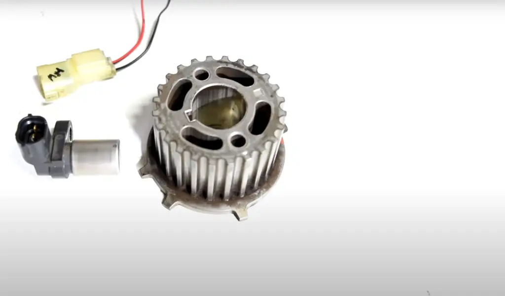
Step 1: Initial Checks
- Ensure that the multimeter is set to the resistance (Ω) setting. [3]
- Confirm that the vehicle’s ignition is turned off.
- Locate and disconnect the electrical connector from the crankshaft sensor.
Step 2: Identify Sensor Terminals
- Examine the crankshaft sensor to identify the terminals. These are the points where you’ll connect the multimeter probes.
- Most crankshaft sensors have two terminals. If you’re unsure about the terminals, consult the vehicle’s repair manual.
Step 3: Connect Multimeter Probes
- Connect the positive (red) probe of the multimeter to one of the sensor’s terminals.
- Connect the negative (black) probe to the other terminal.
Step 4: Record Initial Resistance
- Take note of the initial resistance reading displayed on the multimeter.
- Compare this reading to the specifications provided in the vehicle’s repair manual. Deviations from the expected range may indicate a problem with the sensor.
Step 5: Check for Continuity
- While still connected, gently wiggle the crankshaft sensor wiring and connectors.
- Observe the multimeter for any fluctuations in the resistance reading.
- A sudden change or intermittent readings may suggest a wiring or connector issue.
Step 6: Testing Across Terminals
- If applicable, you may also measure the resistance between each sensor terminal and the sensor body (ground).
- Again, compare these readings to the specifications in the repair manual.
Step 7: Reconnect the Sensor
- Once testing is complete, reconnect the electrical connector to the crankshaft sensor.
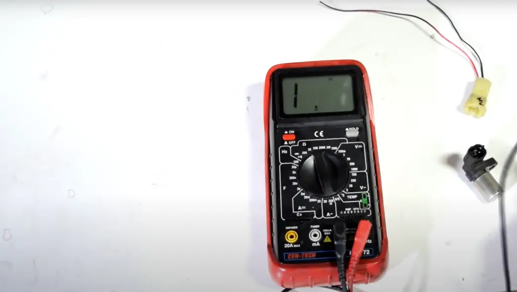
Interpreting the Readings:
- Within Specified Range: If the resistance readings match the specified range in the repair manual, the crankshaft sensor is likely functioning correctly.
- Out of Specified Range: If the readings are outside the specified range, it indicates a potential issue with the sensor. Consult the repair manual for further guidance on interpreting out-of-spec readings. [3]
- Intermittent Readings or Fluctuations: Intermittent readings or fluctuations may point to a wiring or connector problem. Inspect the wiring harness and connectors for damage or poor connections.
By following these steps, you’ll be equipped to use your multimeter effectively to test the crankshaft sensor and gain valuable insights into your vehicle’s health.
Interpreting Results
Understanding the significance of the readings is crucial in determining the health of the crankshaft sensor. Let’s delve deeper into the interpretation of results, distinguishing between normal and abnormal readings.
Normal Readings
Within Specified Range: If the resistance readings fall within the specified range provided by the vehicle’s manufacturer, it indicates that the crankshaft sensor is operating within the expected parameters. In such cases, the sensor is likely in good condition, and other areas of the engine or electrical system should be explored if issues persist.
Abnormal Readings
Out of Specified Range: If the resistance readings are outside the specified range, it suggests a potential problem with the crankshaft sensor. Deviations could be indicative of internal sensor issues, such as a damaged coil or a malfunctioning Hall-effect sensor.
Intermittent Readings or Fluctuations: Intermittent readings or fluctuations may signal wiring or connector problems. This could include issues like a broken wire, a loose connection, or corrosion. These problems can disrupt the sensor’s ability to provide consistent signals to the engine control module [4].
Zero or Infinite Resistance
A reading of zero resistance (a short circuit) or infinite resistance (an open circuit) is abnormal and indicates a serious issue. A short circuit may suggest a damaged sensor coil, while an open circuit could be due to a broken wire or a failed internal component.
Testing Across Terminals
When measuring the resistance between each sensor terminal and the sensor body (ground), readings should generally be infinite (open circuit). A non-infinite reading may indicate a short circuit to the ground, which could affect the sensor’s performance.
Comparing Readings
It’s essential to compare the obtained readings with the specifications outlined in the vehicle’s repair manual. Differences from these specifications can help pinpoint the nature of the problem and guide further diagnostics.
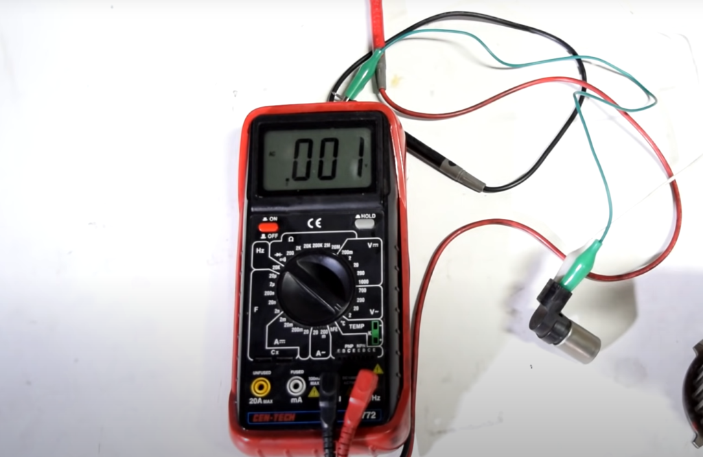
Additionally, consulting the vehicle’s specific diagnostics procedures or seeking professional advice is recommended for a comprehensive diagnosis.
Mastering the art of interpreting multimeter readings when testing a crankshaft sensor is a valuable skill for any DIY mechanic. It empowers you to diagnose potential issues accurately and efficiently, ensuring your vehicle’s engine operates at its best.
Troubleshooting Tips
While testing the crankshaft sensor with a multimeter is a critical step in diagnosing issues, understanding common problems and implementing troubleshooting methods can provide a more comprehensive approach to resolving potential concerns.
Common Issues and Troubleshooting Methods:
-
- Wiring and Connector Issues: Examine the wiring harness and connectors for signs of damage, corrosion, or loose connections. Repair or replace any damaged components.
- Sensor Mounting and Alignment: Ensure the crankshaft sensor is properly mounted and aligned. A misaligned or loosely mounted sensor can lead to erratic readings. Adjust the sensor position as necessary.
- Magnetic Ring Damage: In some vehicles, the crankshaft sensor works in conjunction with a magnetic ring on the crankshaft. Inspect the ring for damage or missing teeth, as this can affect sensor performance.
- Faulty Sensor: If all else seems in order, consider the possibility of a faulty sensor. Substituting the sensor with a known-good unit or using advanced diagnostic tools, such as an oscilloscope, can provide a more detailed analysis.
Additional Checks for Sensor Functionality:
-
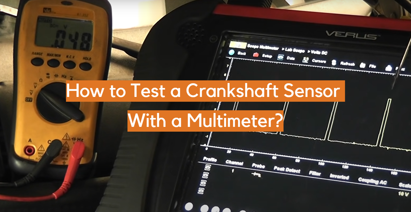
- Output Signal Testing: While the multimeter measures resistance, it’s also valuable to check the sensor’s output signal during engine cranking. An oscilloscope can help visualize the waveform, providing insights into the sensor’s performance. [4]
- Heat Testing: Some crankshaft sensor issues may be temperature-related. Perform testing when the engine is cold and again when it’s warm to observe any variations in sensor behavior.
- Consult Diagnostic Trouble Codes (DTCs): Modern vehicles are equipped with onboard diagnostics that store trouble codes when an issue is detected. Use a diagnostic scanner to retrieve any stored DTCs related to the crankshaft sensor.
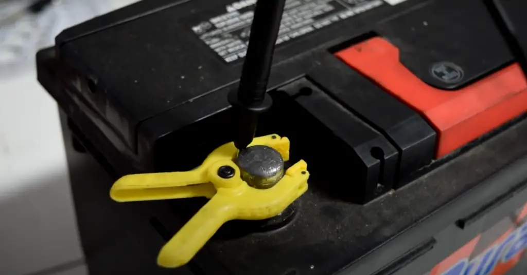
- Check Power Supply: Ensure the sensor is receiving the correct voltage supply. Use the multimeter to measure the voltage at the sensor’s power supply terminals. Inconsistent or low voltage can lead to sensor malfunctions.
- Inspect Ground Connections: A reliable ground connection is essential for sensor operation. Check the continuity and resistance between the sensor ground terminal and the vehicle’s ground point. Clean or repair ground connections as needed.
Troubleshooting can be a systematic process, and it’s often necessary to perform multiple checks to identify the root cause of an issue. Combining multimeter testing with these additional checks provides a more thorough examination of the crankshaft sensor and its associated components.
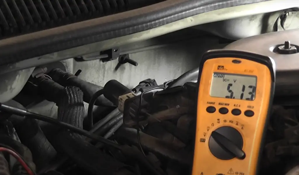
The art of troubleshooting the crankshaft sensor with a multimeter involves combining technical knowledge, practical skills, and a methodical approach. By incorporating these tips into your diagnostic toolkit, you’ll be better equipped to address issues and ensure the optimal performance of your vehicle’s engine.
FAQs
What are the common symptoms of a bad/faulty crankshaft position sensor?
Common symptoms of a faulty crankshaft position sensor include engine misfires, rough idling, stalling, difficulty starting the engine, and a decrease in fuel efficiency. Additionally, the malfunction indicator light (MIL) on the dashboard may illuminate.
How can a multimeter be used to test a crankshaft position sensor?
To test a crankshaft position sensor with a multimeter, set the multimeter to the resistance (Ω) setting. Disconnect the sensor, connect the probes to its terminals, and measure the resistance. Compare the readings with the specifications in the vehicle’s repair manual. Additionally, check for continuity and potential issues by wiggling the sensor wiring and connectors.
What are the typical readings to expect when testing a crankshaft sensor with a multimeter, such as signal voltage, resistance, and pulse width?
Typical readings vary based on the vehicle’s make and model. For resistance, compare readings to specifications; for signal voltage, it often ranges between 0.2 and 5 volts during cranking. Pulse width, measured with an oscilloscope, varies but should exhibit a consistent and smooth waveform.
What are the differences between testing a 2-wire crankshaft position sensor and a 3-wire crankshaft position sensor with a multimeter?
While the basic testing principles remain the same, a 2-wire sensor typically involves measuring the resistance between its terminals, while a 3-wire sensor may include checking the resistance between each terminal and the sensor body (ground). The additional wire in the 3-wire sensor often serves as a dedicated ground connection.
What potential issues can be identified when testing a crankshaft sensor with a multimeter, and how can these be resolved?
A: Potential issues include out-of-spec resistance readings, intermittent readings, or fluctuations. These can indicate sensor, wiring, or connector problems. Resolution involves repairing or replacing damaged components, ensuring proper sensor alignment, and considering advanced diagnostic tools for a more detailed analysis. Always consult the vehicle’s repair manual for specific guidance.
Can a bad crankshaft position sensor cause my engine to stall while driving?
Yes, a faulty crankshaft position sensor can lead to engine stalling while driving. The sensor plays a crucial role in providing the engine control module with accurate timing information, and a malfunction can disrupt the engine’s operation.
Is it possible to drive with a malfunctioning crankshaft position sensor?
While it might be possible to drive with a faulty sensor, it is not recommended. A malfunctioning sensor can lead to performance issues, reduced fuel efficiency, and potential engine damage over time. It’s advisable to address the issue promptly.
Can I visually inspect the crankshaft position sensor for issues without using a multimeter?
Yes, a visual inspection is a good first step. Check the sensor for signs of damage, such as cracks or corrosion. Ensure it is securely mounted and properly aligned. However, a multimeter test is essential for a more accurate assessment of the sensor’s internal condition.
How often should I test the crankshaft position sensor with a multimeter?
Testing frequency depends on factors such as the age of the vehicle, symptoms of engine issues, or routine maintenance schedules. If you experience performance issues or notice symptoms associated with a faulty sensor, it’s advisable to test it promptly. Regular diagnostic checks during routine maintenance can also help catch potential problems early.
Can a multimeter test conclusively determine if the crankshaft position sensor is the sole cause of my engine issues?
While a multimeter test is a valuable diagnostic tool, it may not conclusively determine if the crankshaft position sensor is the sole cause of engine issues. Other factors, such as the sensor’s output signal during cranking, diagnostic trouble codes, and advanced tools like oscilloscopes, may be necessary for a more comprehensive analysis.
Can you test a crank sensor with an oscilloscope?
Yes, testing a crankshaft position sensor with an oscilloscope is a common and effective method in automotive diagnostics. An oscilloscope allows you to visualize the electrical signals produced by the crankshaft sensor, providing more detailed insights into its performance compared to a simple multimeter.
Conclusion: Unraveling the Mysteries of Crankshaft Sensor Testing
In the intricate landscape of automotive diagnostics, the ability to test and troubleshoot components like the crankshaft sensor is an invaluable skill for any DIY mechanic or enthusiast. Armed with a multimeter and a systematic approach, you can delve into the heart of your vehicle’s engine, identifying issues that might otherwise remain hidden.
Throughout this guide, we’ve explored the fundamental steps of testing a crankshaft sensor with a multimeter, from understanding the tool’s functions to interpreting readings and troubleshooting common issues. By following the outlined procedures and considering additional checks, you empower yourself to diagnose and address potential problems, ensuring your engine operates with the precision it deserves.
As with any automotive endeavor, patience and attention to detail are key. The multimeter serves as your trusted ally, allowing you to measure resistance, identify abnormalities, and gain insights into the health of the crankshaft sensor. Whether you’re faced with symptoms of a malfunctioning sensor or are simply honing your diagnostic skills, this guide equips you with the knowledge needed to navigate the testing process confidently.
Remember, while the multimeter is a powerful tool, it is part of a broader diagnostic toolkit. Advanced tools, consultation with a professional mechanic, and referencing the vehicle’s repair manual can provide a more comprehensive understanding of engine issues.
So, the next time your engine exhibits signs of distress, grab your multimeter and embark on the journey of unraveling the mysteries behind the crankshaft sensor. Armed with knowledge and hands-on experience, you’re well on your way to keeping your vehicle’s heartbeat strong and steady. Happy testing!
References
- https://axleaddict.com/auto-repair/How-to-Test-a-Crankshaft-Position-Sensor-Using-a-Multimeter
- https://electrouniversity.com/how-to-test-3-wire-crank-sensor-with-multimeter/
- https://www.1aauto.com/content/articles/crank-sensor-testing
- https://cecas.clemson.edu/cvel/auto/sensors/shaft-position.html




Leave a Reply