The 2N3904 is a popular and versatile bipolar junction transistor (BJT) that is widely used in electronic circuits for various applications. As one of the most commonly available transistors, it has found its place in numerous projects, ranging from amplifiers and oscillators to digital logic circuits and switching applications. To fully harness the potential of this transistor, it is crucial to have a clear understanding of its pinout configuration and how it affects its functionality within a circuit.
In this comprehensive guide, we will delve into the intricacies of the 2N3904 transistor pinout, providing a detailed overview of its terminals and their respective functions. We will explore the physical structure of the transistor, highlighting its three pins and their specific roles. Furthermore, we will discuss the significance of correctly identifying and connecting the pins in order to achieve the desired circuit behavior.
The Guide To 2N3904 Transistor:
Working Principle of 2N3904 Transistor
When a small current is applied to the base terminal, the transistor begins to conduct current between the collector and emitter terminals. This current amplifies the signal at the base, allowing the transistor to be used as an amplifier. The amount of current that flows between the collector and emitter is controlled by the amount of current flowing into the base [1].
How To Use a 2N3904 Transistor?
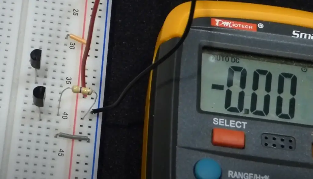
The 2N3904 transistor can be used as a simple electronic switch or as an amplifier. To use it as a switch, the transistor must be biased to be either fully on or fully off in order to control the flow of current through a circuit.
To use the transistor as an amplifier, a small input signal is applied to the base. The signal is then amplified at the collector and output as a larger signal at the emitter. In order to use the transistor as an amplifier, it needs to be biased appropriately. This typically involves setting the base voltage to a predetermined value using a voltage divider circuit.
Characteristics Of 2N3904 Transistor
The 2N3904 transistor has several characteristics that make it useful in various electronic circuit applications. One of the most important of these is its low power consumption. This makes it ideal for use in battery-operated devices and other low-power applications.
Another important characteristic of the 2N3904 transistor is its ability to operate at high speeds. This makes it useful in applications where high-frequency signals need to be amplified or switched.
The transistor also has a low noise level, which makes it useful for applications where precise amplification of low-level signals is required. Additionally, it has a high gain, meaning that it can amplify small input signals to produce larger output signals.
Advantages of 2N3904 Transistor
One of the key advantages of the 2N3904 transistor is that it is widely available and inexpensive. This makes it easy to use in a wide variety of electronic circuits and projects. Additionally, its small size and low power consumption make it ideal for use in compact or battery-powered devices.
Another advantage of the 2N3904 transistor is that it has a high gain bandwidth. This means that it can amplify signals accurately across a wide range of frequencies. As a result, it is commonly used in radio frequency and audio amplifier circuits.
The 2N3904 transistor is also known for its reliable performance. It has a high tolerance for variations in temperature and can operate in a wide range of conditions. This makes it a popular choice for use in industrial and commercial settings where reliability is critical [2].
Disadvantages of 2N3904 Transistor
One of the main disadvantages of the 2N3904 transistor is that it has a low maximum voltage rating. This means that it cannot be used in applications where high voltages are present. In these situations, a transistor with a higher voltage rating would be required.
Additionally, the 2N3904 transistor has a low maximum current rating. This means that it cannot be used in applications where high currents are present. In these situations, a transistor with a higher current rating would be required [3].
Applications of 2N3904 Transistor:
Switching Loads Under 200mA
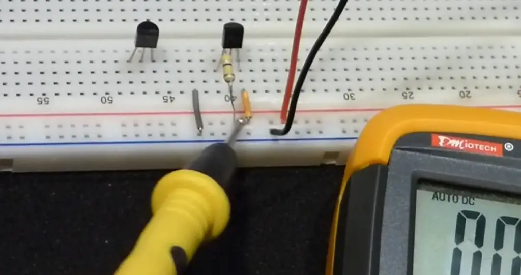
One of the most common uses of the 2N3904 transistor is as a switch for loads under 200mA. The transistor can be used to control the on/off state of a load by acting as a low-side switch. When a signal is applied to the base of the transistor, it conducts current between the collector and the emitter, allowing the load to be switched on. When the signal is removed, the transistor turns off, and the load is switched off. This application is widely used in digital circuits, robotics, and automation.
Sensor Circuits
The 2N3904 transistor can be used in sensor circuits to convert small changes in resistance or voltage into a detectable signal. In such circuits, the transistor is used as a current amplifier to amplify the small current flowing through the sensor. This amplified signal is then processed by the circuit to provide useful information about the sensor’s output.
Audio Preamplifiers
The 2N3904 transistor is used in audio preamplifier circuits to amplify small signals from microphones or other low-level sound sources. The transistor provides high gain and low noise, making it ideal for use in such applications. Moreover, the transistor’s small size makes it an ideal choice for compact audio preamp designs [4].
Audio Amplifier Stages
The 2N3904 transistor can also be used in audio amplifier stages. When combined with other components such as capacitors and resistors, the transistor can be used to amplify audio signals to a higher level for driving speakers or headphones. The transistor’s high gain and low noise make it ideal for use in audio amplifier stages.
Darlington Pairs
In this configuration, the first transistor amplifies the input signal, while the second transistor provides additional amplification. The Darlington pair is widely used in power amplifier circuits, motor control circuits, and other applications that require high levels of amplification.
2N3904 Transistor as a Switch
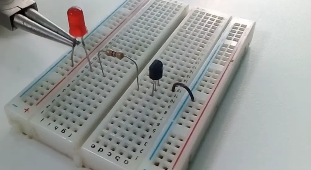
The 2N3904 transistor can be effectively utilized as a switch in electronic circuits, allowing for the control of larger currents or voltages using a smaller control signal. When used in switch mode, the transistor operates in either cutoff or saturation regions, providing an “on” or “off” state for the circuit.
Here is a step-by-step guide on using the 2N3904 transistor as a switch:
- Understanding the pinout: Familiarize yourself with the pin configuration of the 2N3904 transistor. The transistor has three pins: the emitter (E), base (B), and collector (C). The emitter is usually connected to the ground (common reference), the base receives the control signal, and the collector is connected to the load or the circuit being switched;
- Determining the load requirements: Identify the load you want to control using the transistor switch. Determine the load’s voltage and current specifications, as these will influence the selection of appropriate resistors and the power handling capability of the transistor;
- Selecting base resistor: Calculate the base current (IB) required to saturate the transistor and turn it “on” completely. The base current is determined by the load current (IL) and the transistor’s current gain (hfe). Using Ohm’s law (IB = IL / hfe), calculate the required base current. Choose a base resistor (RB) that limits the base current within a safe range, typically around 1/10th of the calculated value. RB can be calculated using RB = (Vcontrol – VBE) / IB, where Vcontrol is the control signal voltage and VBE is the base-emitter voltage drop (approximately 0.7V for a silicon transistor);
- Connecting the transistor: Connect the components as per the circuit diagram. Connect the emitter of the transistor to the ground or common reference point. Connect the collector to the positive supply voltage and the load. Connect the base to the control signal through the base resistor. Ensure proper polarities while connecting the load and power supply;
- Testing and operation: Apply the control signal to the base of the transistor. When the base current exceeds the threshold, the transistor enters the saturation region and conducts current between the collector and the emitter, effectively switching the load “on.” When the control signal is removed or reduced below the threshold, the transistor enters the cutoff region, turning the load “off”;
- Protection measures: Incorporate protective components like flyback diodes or clamping circuits to suppress voltage spikes generated during switching operations. These measures ensure the safety and longevity of the transistor and other components in the circuit [5];
2N3904 Transistor as an Amplifier
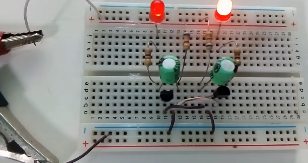
The 2N3904 transistor is commonly used as a general-purpose amplifier in electronic circuits. Its versatile characteristics and availability make it suitable for various applications requiring signal amplification. When utilized as an amplifier, the 2N3904 operates in its active region, where small input signals are amplified to produce larger output signals.
Here is a step-by-step guide on using the 2N3904 transistor as an amplifier:
- Pinout understanding: Familiarize yourself with the pin configuration of the 2N3904 transistor. It consists of three pins: the emitter (E), base (B), and collector (C). The emitter is typically connected to the common ground, the base receives the input signal, and the collector provides the amplified output;
- Biasing the transistor: Establish a proper DC bias for the transistor by applying a suitable voltage to the base-emitter junction. This biasing voltage determines the operating point of the transistor and ensures it remains in the active region. Use a voltage divider network, consisting of resistors, to create the desired bias voltage. Refer to the transistor’s datasheet for recommended biasing conditions;
- Coupling capacitors: Incorporate coupling capacitors to block DC voltage and allow only the AC component of the input and output signals to pass through. Connect a capacitor in series with the input signal at the base terminal and another capacitor in series with the output signal at the collector terminal. These capacitors prevent the DC bias from affecting the input and output signals;
- Load resistor: Connect a load resistor between the collector terminal and the positive power supply voltage. The load resistor determines the gain of the amplifier and provides a load for the amplified signal;
- Input and output impedance matching: To ensure efficient signal transfer between the input and output stages, match the input impedance of the amplifier with the source impedance and match the output impedance of the amplifier with the load impedance. This impedance matching optimizes the power transfer and minimizes signal reflections;
- Testing and adjustment: Apply the input signal to the base terminal and observe the amplified output signal across the load resistor. Adjust the biasing network, such as the voltage divider resistors, to achieve the desired operating point and optimize the amplifier’s performance. Use an oscilloscope or a multimeter to measure and analyze the input and output signals;
- Stability and compensation: If necessary, add compensation components like capacitors or resistors to improve stability and prevent oscillations in the amplifier circuit. These components are typically determined based on the frequency response and desired bandwidth of the amplifier [6];
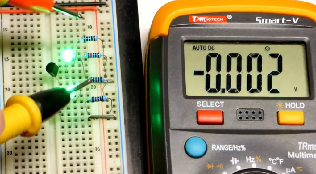
About 2N3904 Pinout:
Pinout Diagram
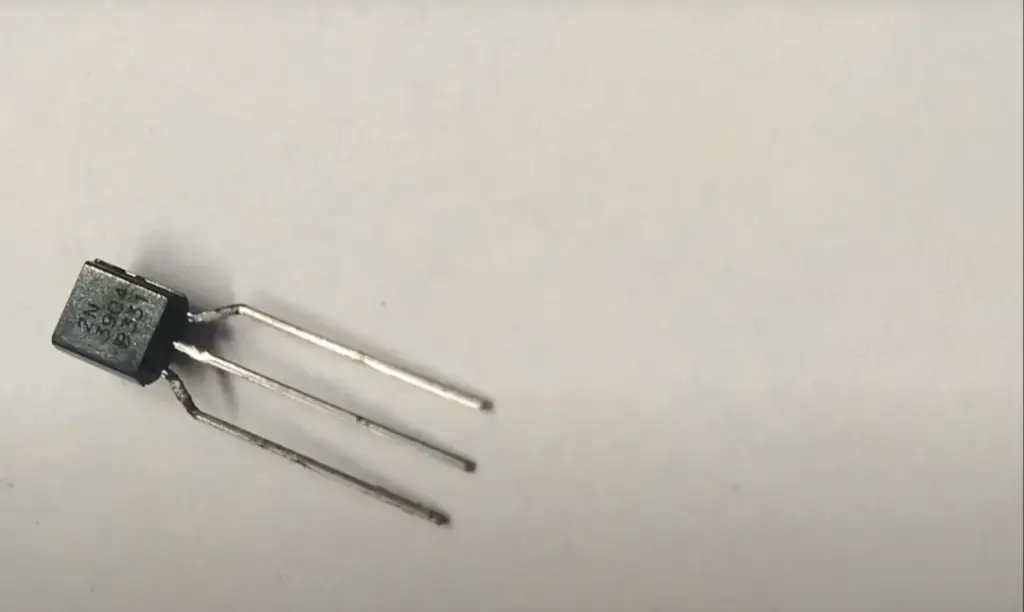
The 2N3904 transistor features 3 pins: the emitter (E), base (B), and collector (C). The pinout diagram provides a visual representation of the transistor’s pins and their physical arrangement. It helps in identifying the correct orientation and connection of the transistor within a circuit.
Pin Configuration:
- Emitter (E): The emitter pin is denoted as “E” in the pin configuration. It is heavily doped to facilitate the emission of majority carriers (electrons for an NPN transistor like the 2N3904). The emitter is typically connected to the ground or common reference point of the circuit;
- Base (B): The base pin is denoted as “B” in the pin configuration. It is responsible for controlling the transistor’s conduction state. By applying a small current or voltage to the base, the transistor can be turned “on” or “off”, enabling it to amplify signals or act as a switch. The base-emitter junction is forward-biased to allow current flow from the emitter to the base;
- Collector (C): The collector pin is denoted as “C” in the pin configuration. It is responsible for collecting the majority of carriers (electrons for an NPN transistor) emitted from the emitter. The collector is typically connected to the load or the output of the circuit;
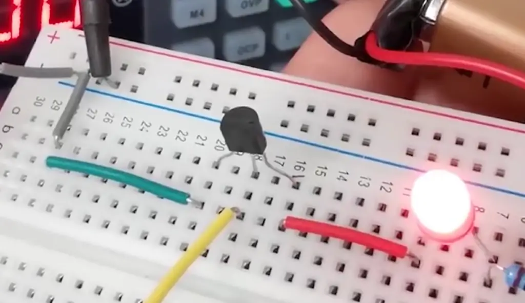
2N3904 Bipolar Transistor:
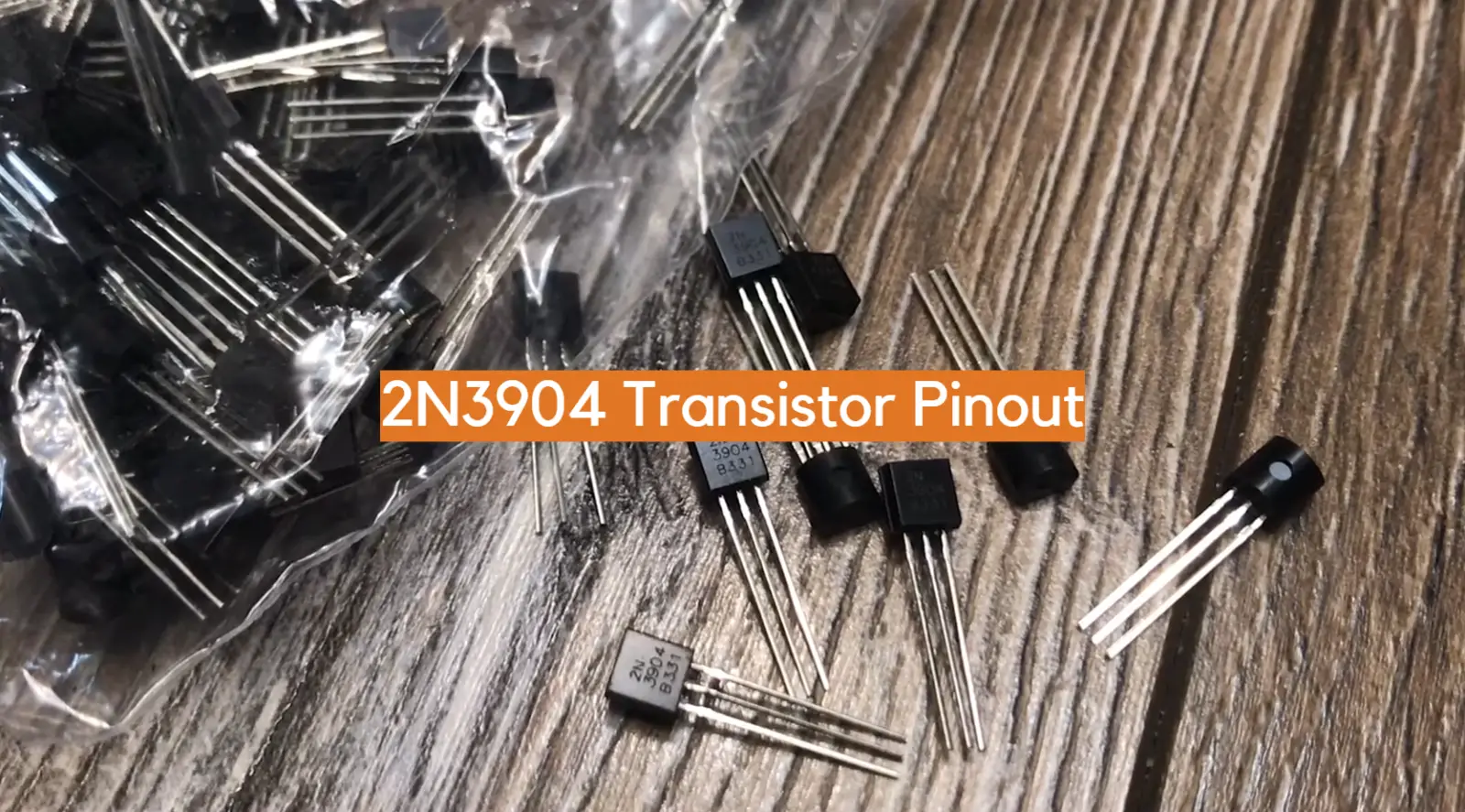
Pinout of 2N3904 Transistor
In most circuit diagrams, the emitter lead is denoted by a downward-pointing arrow. The base lead is typically located between the emitter and collector leads, and it is denoted by a diagonal line.
Complementary PNP Transistor
As an NPN-type transistor, the 2N3904 requires a complementary PNP-type transistor to form a complete circuit. A complementary PNP transistor for 2N3904 is 2N3906. Unlike the 2N3904, the 2N3906 has an opposite polarity and can be used as a switch or an amplifier in circuits where a PNP transistor is required.
SMD Version of 2N3904 Transistor
Surface-mount version or SMD of the 2N3904 transistor is marked as MMBT3904. It has a similar pinout as the through-hole version, but its packaging is much smaller. The SMD package allows for a more compact circuit design, and it is widely used in mobile devices, laptops, and other portable electronics.
2N3904 Transistor in TO-92 Package
The TO-92 package is a popular packaging for the 2N3904 transistor. This package is relatively small and is easy to use. The 2N3904 TO-92 package makes it an ideal choice for use in general-purpose circuits, such as audio and video amplifiers, power supplies, and timers. Additionally, the TO-92 package is low-cost and easy to assemble, making it a popular choice for hobbyists and electronics enthusiasts [7].
Replacement and Equivalent for 2N3904 Transistor
Several replacement and equivalent transistors to the 2N3904 are commonly used in electronic circuits. One of the top replacements is the BC547 transistor. The BC547 has similar characteristics as the 2N3904 and is often used as a substitute in audio amplifiers, metal detectors, and other applications. Another equivalent transistor to the 2N3904 is the PN2222A, which has a higher current rating and a more extended operating temperature range.
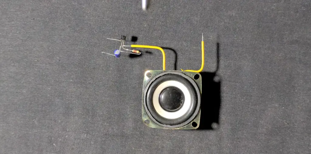
2N3904 Spice Model
The 2N3904 transistor can also be modeled using Spice software, which is commonly used in electronic circuit simulation. The Spice model of 2N3904 provides a mathematical representation of the transistor’s behavior and allows for a more accurate simulation of circuits that include the 2N3904. The Spice model parameters include the transistor’s current gain, base-emitter saturation voltage, and other electrical characteristics.
Where And How to Use 2N3904?
The 2N3904 is a common NPN bipolar junction transistor that is used for general-purpose low-power amplifying or switching applications. It is designed for low current and power, medium voltage, and can operate at moderately high speeds. It is complementary to the 2N3906 PNP transistor and both types were registered by Motorola Semiconductor in the mid-1960s.
In terms of where to use the 2N3904, it is mostly used for lower-power amplifiers and switching applications.
Its major functional area is enclosed in a TO-92 package, but electrically similar devices, such as the MMBT3904, are available in a variety of small through-hole and surface-mount packages, including TO-92, SOT-23, and SOT-223.
It is important to note that the package type used depends on the thermal rating needed for the specific application.
As for how to use the 2N3904, it can be used as a simple electronic switch or amplifier. When used as a switch, the transistor is biased to be either fully on or fully off in order to control the flow of current through a circuit. When used in an amplifier, the transistor amplifies a small input signal into a larger output signal.
It is also worth mentioning that the 2N3904 is a standard commercial product and is not intended for use in applications that require extraordinary performance or reliability such as nuclear facilities, aircraft systems, or life support systems.
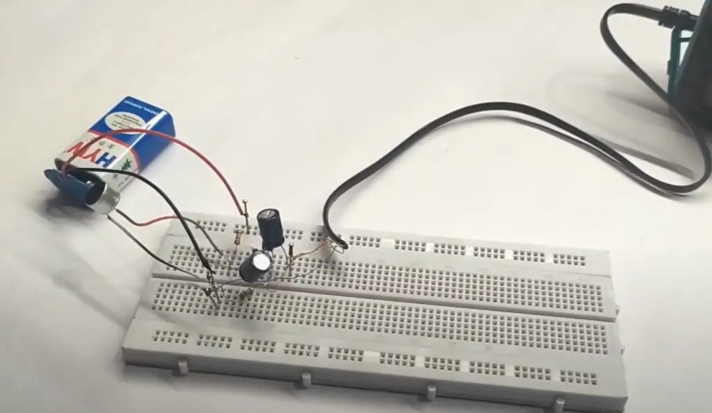
How to Safely Long Run 2N3904 in a Circuit?
Running the 2N3904 transistor in a circuit for extended periods requires careful consideration and implementation of certain precautions to ensure its safe and reliable operation.
Here are some guidelines to help you safely long-run the 2N3904 transistor:
- Determine the maximum ratings: Before integrating the 2N3904 transistor into your circuit, it is crucial to understand its maximum ratings. These specifications include the maximum collector current (IC), maximum collector-emitter voltage (VCEO), and maximum power dissipation (Pd). Operating the transistor within these limits is vital to prevent thermal damage and ensure its longevity;
- Calculate power dissipation: When designing your circuit, calculate the power dissipation across the 2N3904 transistor. Excessive power dissipation can lead to overheating and potential failure. Ensure that the power dissipated is within the specified limits by monitoring the voltage drop across the collector-emitter junction and the collector current;
- Use appropriate biasing: Proper biasing is crucial to maintain the 2N3904 transistor’s operating point within its desired region. This involves setting the correct base current (IB) using appropriate resistors and ensuring a stable DC bias. Follow the transistor’s datasheet and consider using a suitable biasing network, such as a voltage divider, to achieve the desired operating conditions;
- Implement adequate cooling: If your circuit requires the 2N3904 transistor to handle high power or operate in a high-temperature environment, ensure proper cooling mechanisms. Consider using heat sinks, thermal pads, or fans to dissipate heat effectively and prevent the transistor from overheating;
- Protect against voltage spikes: Transients, such as voltage spikes or inductive kickback, can damage the 2N3904 transistor. Protect the transistor by incorporating suitable protection circuits, such as flyback diodes or clamping circuits, to suppress these transients and ensure reliable operation;
- Monitor temperature: Continuously monitor the operating temperature of the 2N3904 transistor during long runs. Excessive heat can degrade the transistor’s performance and significantly reduce its lifespan. Use temperature sensors or thermal imaging to detect any overheating issues and take necessary measures to mitigate them;
- Ensure proper PCB layout: When designing the printed circuit board (PCB) for your circuit, pay attention to the proper placement and routing of the 2N3904 transistor. Minimize the length of high-current traces and avoid proximity to sensitive components to minimize interference and maximize performance;
FAQ
1. What is a 2N3904 transistor used for?
The 2N3904 transistor is commonly used for a wide range of applications in electronic circuits. It is primarily utilized as a general-purpose NPN (negative-positive-negative) transistor for amplification and switching purposes [8].
It can be employed as a small-signal amplifier to amplify weak signals, as a switch to control larger currents or voltages with a small control signal, or as a component in oscillator and timer circuits. Its versatility makes it suitable for various applications in audio amplifiers, signal conditioning circuits, motor drivers, LED drivers, and more.
2. Can I use BC547 instead of 2N3904?
Yes, you can generally use a BC547 transistor as a substitute for a 2N3904. Both transistors are NPN types and have similar characteristics, such as maximum voltage and current ratings. However, there might be slight differences in the electrical and thermal characteristics between the two transistors, such as gain (hfe) and frequency response, so it’s recommended to consult the datasheets and consider the specific requirements of your circuit before substituting one for the other.
3. What is the difference between 2N2222 and 2N3904?
The main difference between the 2N2222 and 2N3904 transistors lies in their electrical and thermal characteristics. The 2N2222 is also an NPN transistor and shares some similarities with the 2N3904. However, the 2N2222 generally has a higher current gain (hfe) and a higher maximum collector current (IC) compared to the 2N3904 [9].
Additionally, the 2N2222 can handle slightly higher power dissipation (Pd) and has a higher collector-emitter voltage rating (VCEO). It’s important to review the datasheets of both transistors to understand their specific parameters and select the appropriate one based on your circuit requirements.
4. How much current can 2N3904 output?
The maximum collector current (IC) that a 2N3904 transistor can handle is typically around 200mA. However, the exact value may vary depending on factors such as temperature and the specific manufacturer’s datasheet. It’s crucial to ensure that the load connected to the transistor does not exceed this maximum current rating to prevent damage to the transistor and maintain reliable operation.
5. What is the maximum voltage for 2N3904?
The maximum collector-emitter voltage (VCEO) for the 2N3904 transistor is typically around 40V. Exceeding this voltage rating can cause breakdown and damage to the transistor. It’s important to consider the voltage requirements of your circuit and ensure that the VCEO rating of the transistor is sufficient to handle the applied voltage.
6. Is 2N3904 a PNP?
No, the 2N3904 is an NPN (negative-positive-negative) transistor. In an NPN transistor, the majority of carriers are electrons, and current flows from the emitter to the collector when the base-emitter junction is forward-biased.
7. Which is better – BC108 or 2N3904?
The choice between BC108 and 2N3904 depends on the specific requirements of your circuit and the availability of the transistors. Both transistors are NPN types and have similar characteristics. However, there might be slight differences in their electrical parameters and performance.
8. What is 2N3904 TO-92?
2N3904 is a bipolar junction transistor (BJT) that comes in a TO-92 package. It is an NPN-type transistor commonly used in electronic circuits as a switch or an amplifier. The TO-92 package is a small, versatile, and low-cost packaging that makes the 2N3904 transistor an ideal choice for use in general-purpose circuits.
9. What is the price of a 2N3904 NPN transistor?
The price of a 2N3904 NPN transistor varies depending on the manufacturer, quantity, and supplier. However, on average, one 2N3904 NPN transistor typically costs around $0.05 to $0.10. The price can be cheaper when purchased in bulk quantity.
10. Is 2N2222A NPN or PNP?
2N2222A is an NPN-type bipolar junction transistor. It is commonly used as a switch or an amplifier in electronic circuits. The complementary PNP-type transistor for 2N2222A is 2N2907A.
11. What is the difference between 2N3904 and 2N3903?
2N3904 and 2N3903 are both NPN-type transistors with identical pinouts. However, the 2N3903 transistor has a slightly higher collector current rating and lower current gain compared to the 2N3904 transistor. In terms of application, they can be used interchangeably in most cases.
12. What is the maximum power of 2N2222?
2N2222A has a maximum power dissipation of 625 mW. This specification indicates the maximum amount of heat that the transistor can dissipate under ideal conditions without damage to the device.
13. How much voltage can a 2N2222 handle?
2N2222A can handle a maximum voltage of 30V. However, the operating voltage range is usually lower than the maximum rating and depends on the specific application circuit.
14. What is the difference between 2N5088 and 2N3904?
2N5088 and 2N3904 are both NPN-type general-purpose transistors. However, 2N3904 has a lower maximum collector current rating and a lower voltage rating than 2N5088. Additionally, 2N5088 has a higher transition frequency and a higher current gain than 2N3904.
15. What is the operating frequency of 2N3904?
The operating frequency of the 2N3904 transistor can vary based on the specific application and circuit design. However, typically 2N3904 transistor has a high-frequency response, and it can operate in the range of several megahertz to tens of megahertz.
16. What is the minimum voltage for 2N3904?
The 2N3904 transistor does not have a specific minimum voltage requirement. However, it is important to note that the transistor requires a certain amount of voltage to enter the active region and amplify the signal. The minimum voltage required for the transistor to turn on and operate in the active region depends on the circuit design, specific application, and the biasing of the transistor.
17. Which transistor is used in a Tesla coil?
A Tesla coil can use several types of transistors depending on the circuit design and the required power output. However, some commonly used transistors in Tesla coils include power MOSFETs, IGBTs (Insulated Gate Bipolar Transistors), and BJTs (Bipolar Junction Transistors). Specific transistor selection depends on various factors such as voltage and current requirements, frequency range, and switching characteristics.
18. Can I use 2N2222 instead of C945?
2N2222 and C945 are both bipolar junction transistors, but they have different characteristics and specifications. The 2N2222 transistor is an NPN-type transistor, while C945 is a PNP-type transistor. Therefore, they cannot be used interchangeably. Substituting a transistor requires a thorough understanding of the application and circuit design, as it involves matching the specifications and characteristics of the original transistor with the replacement transistor.
19. What is the use of the 2N5401 transistor?
2N5401 transistor is a PNP-type transistor that is commonly used as an amplifier or switch in electronic circuits. It has a high gain, low noise, and low saturation voltage, making it an ideal choice for audio amplifiers and other low-power applications. Additionally, its low collector-emitter saturation voltage and high current gain make it well-suited for use in switching applications.
Useful Video: 2n3904 Transistor | Pinout and equivalent transistors
References
- https://www.etechnophiles.com/2n3904-transistor-pinout-datasheet-specs/
- https://components101.com/transistors/2n3904-pinout-datasheet
- https://www.el-component.com/bipolar-transistors/2n3904
- https://www.componentsinfo.com/2n3904-pinout-equivalent/
- https://www.utmel.com/components/2n3904-silicon-npn-transistor-faq-datasheet-pinout-equivalent-and-package?id=1803
- https://www.apogeeweb.net/circuitry/simple-2n3904-circuits.html
- https://www.digikey.com/en/articles/simply-put-2n3904-npn-transistor
- https://www.apogeeweb.net/circuitry/2n3904-datasheet-equivalent-pinout.html
- https://en.wikipedia.org/wiki/2N3904




Leave a Reply