
Did you know that you can measure inductance using a simple multimeter? It’s true! In fact, measuring inductance is quite easy and only requires a few steps. In this blog post, we’ll show you how to measure inductance using a multimeter. We’ll also provide some background information on workflow so that you can understand the process better. Stay tuned!
What Is Inductance?
It is important to note that different types and sizes of coils have different levels of inductance. [1]
How to Measure Inductance?
Impedance Comparison to Resistor
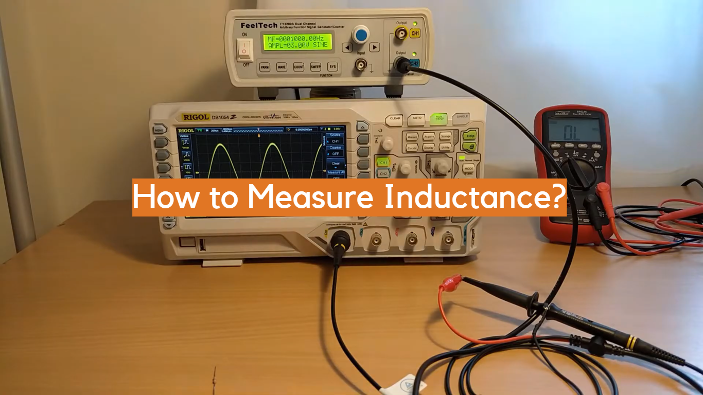
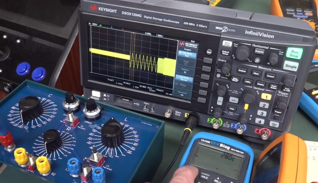
Measuring inductance is not as straightforward as measuring resistance. Inductors behave differently than resistors in that they oppose changes in current flow instead of voltage. This means that the measurement of an inductor’s value requires a steady current source, with a known voltage and frequency, applied to it. The output will then be measured with an oscilloscope or other device which can measure impedance. By comparing the output signal to the input signal, you should be able to calculate the inductance value of your component.
Time Domain Reflectometry
Time domain reflectometry (TDR) is a specialized method used to measure the length of cables as well as their characteristic impedance. It works by sending out pulses along the cable and then measuring the time it takes for the pulse to reflect back off of any discontinuities, such as connectors or wire splices. By knowing the speed of propagation for the signal used, you can then calculate the cable length and its characteristics.
This same method can be used to measure inductance by connecting a known impedance source (such as a resistor) to one end of your inductor. The TDR is then connected to the other end, and by comparing the output with the input signal, you should be able to calculate its value.
Inductance Bridge
An inductance bridge is an electronic device designed specifically for measuring inductors. It works by applying a known AC voltage across two sides of an unknown inductor while measuring current and voltage on both sides. By comparing the two, you should be able to determine the inductance value of your component. You can also use a digital multimeter to measure an inductor’s value by connecting it in series with a known resistor and measuring the voltage drop across it.
Resonant Point with a Capacitor
If you have an inductor and a capacitor of known value, you can measure the inductance by connecting them in series. By varying the frequency of the signal applied to the circuit, you should be able to find the resonant point where the two components are in phase with each other. At this point, the current flowing through both components will be at its maximum, and from this you can calculate their combined reactance as well as the inductance value of your component.

Measuring with an LCR Meter
An LCR meter is a specialized device that can measure both inductance and capacitance. It works by applying a known AC voltage across the component and then measuring the current as well as its phase shift with respect to the input signal. By comparing these two values, you can calculate the reactance of your component and from this, determine its inductance or capacitance value. [2]
Calculating Inductance on a Voltage-Current Slope
If you have an inductor with a known voltage-current slope, then you can calculate its value by measuring the output current when a steady AC signal is applied to it. By plotting the input versus output values on a graph, you should be able to determine the inductance from its slope. This method works especially well if the inductor has low parasitic capacitance and resistance.
Using a Multimeter
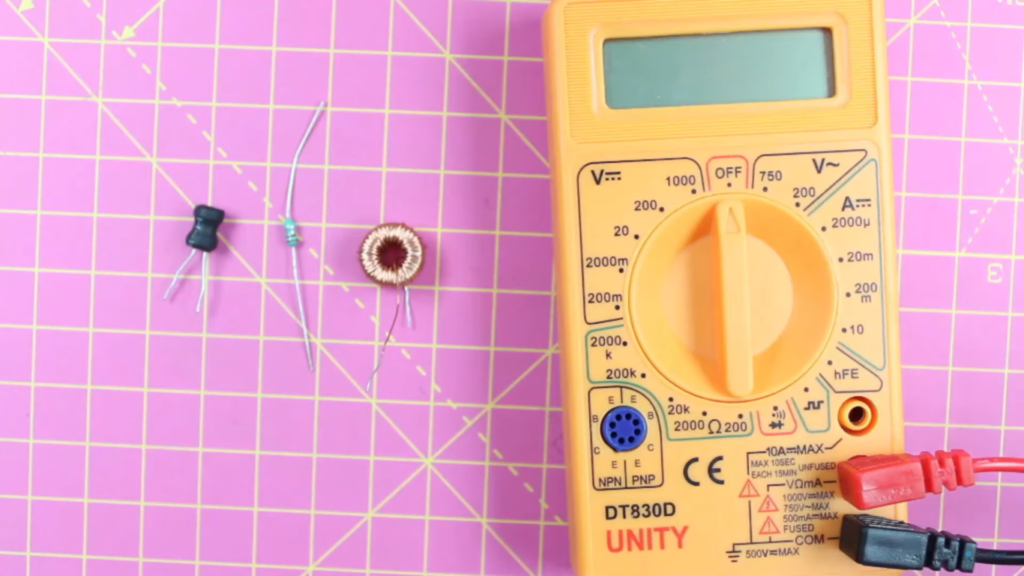
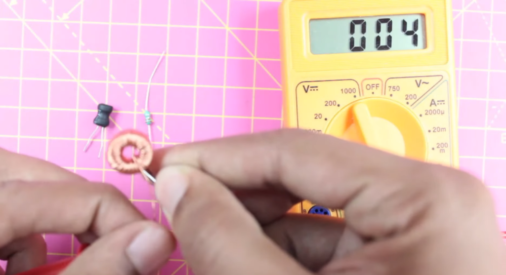
Finally, if you have a digital multimeter (DMM) available, then you can measure the inductance of a component by connecting it in series with a known resistor and measuring the voltage drop across both. By comparing this reading to your expected current output from the DMM, you should be able to calculate its value.
In conclusion, there are many different ways to measure an inductor’s value depending on what equipment is available and the characteristics of your component. Ultimately, all of these methods require some degree of experimentation and may not be suitable for certain applications; however they are useful tools that can help you accurately determine an inductor’s value.
Theory Behind the Estimation of the Inductor Value
To measure the value of an inductor, engineers must first use Ohm’s law to calculate the DC resistance (R) of the coil. If R is known and if there is access to an AC power source with frequency f, then another equation called the mutual-inductance formula can be used to determine L:
L = (R^2*f)/(4*pi^2)
This equation works by measuring the amount of current that flows when an AC voltage is applied to the coil. When the frequency of this voltage is increased, so too does the amount of current that flows through the inductor. That increase in current can be measured and used to calculate L.
It’s important for engineers to remember that these calculations only give a rough estimate of inductance values, since factors like core material, coil geometry and inter-winding capacitance also affect overall performance. As such, it’s best practice to use more accurate methods like a LCR meter or inductance bridge if precise readings are required.
Overall, measuring inductance can be a daunting task for engineers, but understanding the theory and equations behind inductance estimation helps to simplify the process. With the right tools and knowledge, any engineer should be able to accurately measure an inductor’s value. [3]
Uses of Inductors
Inductors are electronic components that are primarily used to create electrical circuits with inductance. This inductance can be used in a variety of ways.
In power supplies, inductors are often used to store energy while the supply is off and then release it when the supply is turned on again. They can also be used as filters to reduce noise and interference in signals. In combination with capacitors, they can form resonant circuits which are used for radio transmission and reception. Finally, they can be combined with transformers to step up or down voltage levels depending on the applications’ needs.
By choosing an appropriate value for the inductor, engineers have significant control over how their circuit will act and behave in different situations. In order to measure the inductance of a given component, several different tools can be used.
How Does An Inductor Work?
An inductor works by creating a magnetic field around itself in response to an electrical current. This magnetic field stores energy, which is then released when the current ceases or reverses direction. The magnitude of this stored energy is referred to as “inductance.” Inductance is measured in units called Henrys (H).
Common examples of inductors can be found in electronics such as radios, TVs and other appliances. They are also used for filtering, signal processing and regulating voltages and currents.
What Happens When You Disconnect the Inductor?
When you disconnect an inductor, the magnetic field it created around itself dissipates quickly and there is an effect known as counter-electromotive force (CEMF). This CEMF works like a short circuit — electrons flow from one end of the inductor to the other, creating a large current flow. This current can damage components if it is not controlled.
To avoid this issue, you should always disconnect the inductor slowly, allowing time for the magnetic field to dissipate gradually. Additionally, you should make sure that any capacitors or other components connected to the inductor are also disconnected before turning off power.
By taking these precautions, you can protect your circuits from potential damage due to excessive current flow when an inductor is disconnected. [4]
How Are Inductors Attached To Circuit Boards?
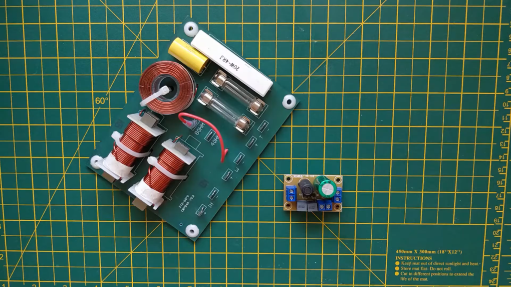
Inductors are typically attached to circuit boards through either a thru-hole or surface mount style. Through-hole mounting is done by drilling a hole in the board and soldering the leads of the inductor into it. Surface mount technology (SMT) involves attaching tiny components directly onto the surface of the PCB with solder paste and a heat gun or reflow oven. SMT is preferred over through-hole for its increased reliability, lower cost, and better electrical performance. To make sure that your inductor is securely attached to your circuit board, always check for any signs of cold solder joints before powering up your device. Additionally, take caution when manipulating an inductor as they can be damaged easily if bent too far or exposed to excessive temperature or vibration.
Inductors are essential components in a variety of electronic designs, from radio frequency power converters to high-voltage power supplies. When working with inductors, it is important to select the right one for your application and make sure it is securely attached to the PCB. Understanding how inductance works and how you can measure it will help you get the most out of your circuit design.
In What Applications Are Inductors Used?
Inductors are commonly used in electrical circuits to create a low-pass, high-pass or band-pass filter, as well as for impedance matching purposes. Examples of inductor usage include radio and audio equipment, telecommunication systems, computers, power supplies and numerous other consumer products.
Their use is widespread in the field of electronics since they can provide energy storage and filtering capabilities with relatively low cost and size requirements. They are also capable of providing a very stable frequency response when used in combination with capacitors. Inductors can also be used for current sensing and protection applications such as limiting inrush currents when components are switched on or off. Generally speaking, inductors are essential components for almost any electronic system.
In some cases, such as high-power applications, special types of inductors called “chokes” are used. These devices act both as inductors and transformers simultaneously, allowing them to provide regulation and filtering of both current and voltage at a given frequency.
Inductors also have many uses in the medical field, primarily for imaging systems like MRI (Magnetic Resonance Imaging) machines, which use powerful electromagnets to create detailed images of internal organs or tissues. Inductors are also used in EKG (electrocardiography) equipment, where they help measure electrical impulses produced by the heart. [5]
Types Of Inductors
Inductors come in a variety of shapes and sizes to suit different applications. Examples include air core coils, powdered iron cores, ferrite or ceramic cores, flat spiral inductors, and toroidal or doughnut-shaped inductors.
Air core coils are usually used for low frequencies because the lack of a magnetic field means that they have low inductance.
Powdered iron cores are useful for higher frequencies due to their high permeability which increases the inductance value compared to an air core coil.
Ferrite or ceramic cores provide even higher permeability than powdered iron cores, making them ideal for very high frequency applications such as radio transmitters and receivers.
Flat spiral inductors are often used in planar transformers and can be wound with a variety of materials, such as silver-plated copper wire.
Toroidal or doughnut-shaped inductors are most commonly used in RF applications and due to their shape, they have the lowest radiated electromagnetic field compared to other types of inductors.
Capacitor vs Inductor
No matter what kind of circuit you’re constructing, capacitors and inductors will often be involved. Both components are essential for a variety of tasks, such as filtering, storing energy or creating resonant circuits.
The two components differ significantly in their behavior towards alternating currents. While capacitors are effective at blocking AC, inductors act as a type of filter and allow it to pass through. This is why they are often used in combination for audio purposes; the capacitor will block lower frequency signals while allowing the higher frequencies to pass through.
When measuring inductance, one must consider several factors. The most important factor is the core material that makes up the inductor, as different materials can affect how much current can be handled and how much voltage will be induced by it. Additionally, other variables such as wire size and winding counts also play a role. [6]
FAQ
How do you calculate inductance?
The most common way to calculate inductance is by using the formula L = (μ x N2 x A) / l, where μ is the permeability of free space, N is the number of turns in the coil, A is the cross-sectional area of the coil and l is the length. You can also measure it directly using an inductance meter or an oscilloscope. You will need to set up an appropriate circuit with a current source and measure the voltage across it. The ratio of voltage to current will give you your value for inductance. Additionally, some devices have built-in circuits that allow you to measure inductance without having to set up a separate circuit. Finally, if you know all of your component values you can also use a simulation program to calculate the inductance.
What is a self-inductance meter?
A self-inductance meter, or an LCR (Inductance Capacitance Resistance) meter, is a device used for measuring the inductance of a circuit. It works by applying an alternating current to the circuit and then measuring the voltage across it. The ratio of voltage to current gives you your value for inductance. This type of measurement can be made quickly and accurately, making it ideal for testing circuits with varying parameters such as frequency or load. Some devices even have built-in functions that allow you to measure inductance without having to build your own circuit.
How do I measure inductance in an AC circuit?
The easiest way to measure inductance in an AC circuit is with an LCR meter. This device applies a known alternating current to the circuit and measures the voltage across it, giving you your value for inductance. Alternatively, if you know all of the component values you can use a simulation program to calculate the inductance. Additionally, some devices have built-in circuits that allow you to measure inductance without having to setup a separate circuit.
What are some common applications of measuring inductance?
Measuring inductance is commonly used for testing electronic components such as transformers or coils, checking printed circuit boards (PCBs), troubleshooting automotive electrical systems and analyzing RFID (Radio Frequency Identification) tags. Additionally, inductance measurements can help identify any unexpected sources of leakage in a circuit and diagnose problems with power supplies or circuits that involve AC current.
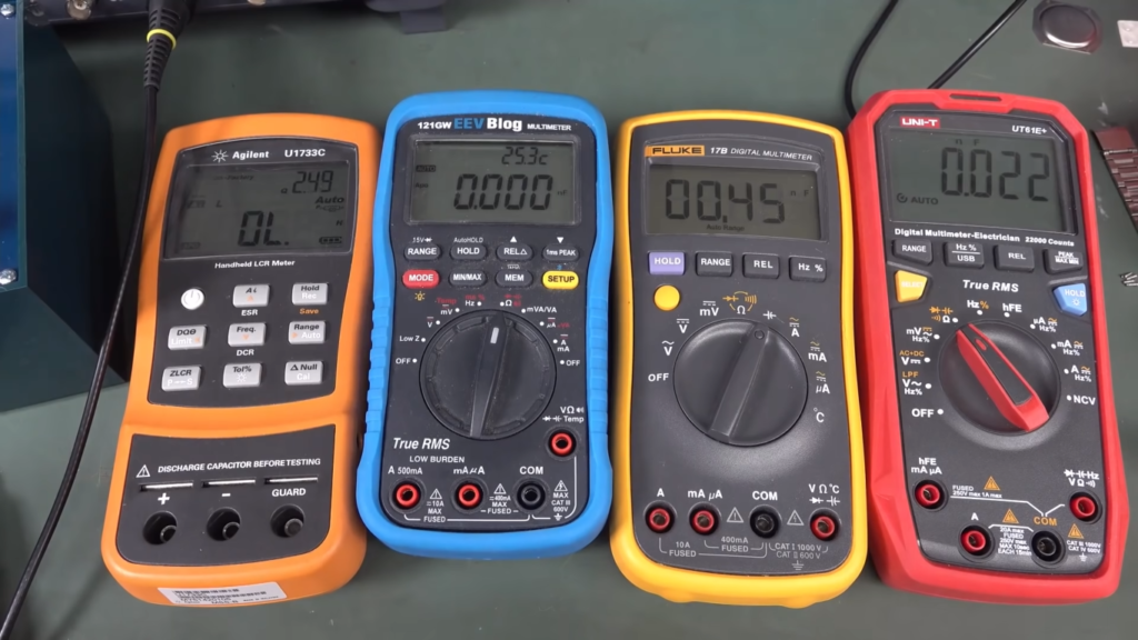
What are the different types of inductance meters?
There are several different types of inductance meters available on the market today. Handheld LCR meters are very popular due to their portability, accuracy and ease-of-use. They use an alternating current source to measure the voltage across a circuit, giving you your value for inductance. Other options include benchtop devices that can provide higher accuracies but require more setup time and knowledge before being used correctly. Finally, some devices have built-in circuits that allow you to measure inductance without having to setup a separate circuit.
What are the limitations of measuring inductance?
The main limitation of measuring inductance is that it is difficult to measure accurately at high frequencies. Additionally, the act of inserting a probe into a circuit can change its characteristics and so readings may not be completely accurate. Finally, some types of circuits cannot be measured with an LCR meter due to their complexity or high frequency nature. It is important to be aware of these limitations before making any measurements.
What are the four 4 factors that determine inductance?
The four factors that determine inductance are the number of turns in a coil, the material used for the core, the shape of the coil and its physical size. Additionally, any change in these factors will affect the value of inductance. For example, increasing the number of turns or decreasing the size of a coil will increase its inductance. It is important to take all of these factors into account when measuring or calculating inductance.
What is the unit of inductance?
The unit of inductance is the henry (H). This is the standard measure for inductance, and all inductors are given a value in henrys. Additionally, any other values such as Farads or Ohms can be converted into henrys with the appropriate formula.
What are the 2 types of inductance?
Inductance can be divided into two main types: self-inductance and mutual inductance. Self-inductance is the property of a circuit or component that stores energy in an electromagnetic field when a current passes through it. Mutual inductance occurs when two separate coils of wire interact with each other, creating a transferring magnetic flux between them which can induce current in either coil. Both types of inductance are measured using different methods depending on the type of inductor involved. For self-induction, one common method is to measure how quickly the voltage rises in response to changes in the current flowing through it. This can be done by connecting an oscilloscope across the component and measuring its rise time as well as its peak voltage.
What is the difference between capacitor and inductance?
The primary difference between a capacitor and an inductor is that capacitors store energy in an electric field, while inductors store energy in a magnetic field. The ability of an inductor to store energy makes it useful for applications such as filtering and signal processing. Capacitors, on the other hand, are used primarily for storing electrical charge and releasing it as needed. Finally, one key difference between the two components is that they both react differently when exposed to alternating currents (AC). Capacitors tend to block or limit AC signals, whereas inductors act as amplifiers or filters for AC signals.
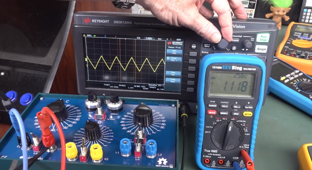
Useful Video: EEVblog 1465 – Your Multimeter Can Measure Inductors
Conclusion
Measuring inductance is an important part of electrical engineering. It helps to determine the amount of current flowing through a conductor or circuit and can be used in various applications such as testing voltage, calculating power consumption, and analyzing circuit behavior. There are several different methods for measuring inductance, including using a multimeter, oscilloscope, bridge impedance analyzer, transformer test set, and Rogowski coils. Each method has its own advantages and disadvantages depending on the task at hand. No matter which method you use however, it’s important to always properly calibrate your instrument in order to get accurate readings. With the right equipment and knowledge of how to measure inductance correctly, engineers can analyze circuits accurately and confidently.
References
- https://www.wikihow.com/Measure-Inductance
- https://www.instructables.com/Measuring-Inductance-With-a-Multimeter-and-a-Resis/
- https://www.testandmeasurementtips.com/how-to-measure-inductance/
- https://www.tek.com/en/documents/application-note/capacitance-and-inductance-measurements-using-oscilloscope-and-function-ge
- https://www.coilcraft.com/en-us/edu/series/what-is-an-inductor/